


Build a Network‑Enabled RFID Card Reader with Arduino, ENC28J60 Ethernet, and MFRC522
Components and supplies
| × | 1 | ||||
 |
| × | 1 | |||
| × | 1 | ||||
 |
| × | 1 | |||
 |
| × | 1 | |||
| × | 1 |
Necessary tools and machines
|
Apps and online services
| ||||
 |
|
About this project
Have you ever thought of adding an RFID tags/card security system or monitoring system in your home and/or office. Well if you got here i bet you already looked up how freaken expensive they are ranging from $200 to $2000, TOO MUCH RIGHT!?? Well a friend and I have decided to make a system that would cost under $100 and could do even more than just access a door, so this is what we came up with. A internet enabled arduino rfid tag reader. that for $20 more can open doors. This system was designed to track students at our highschool and we hope the school approves it.
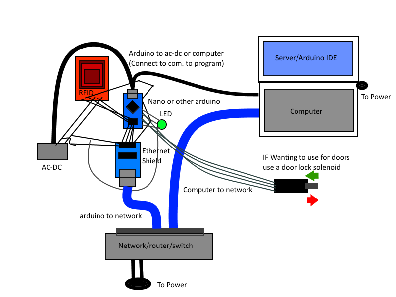
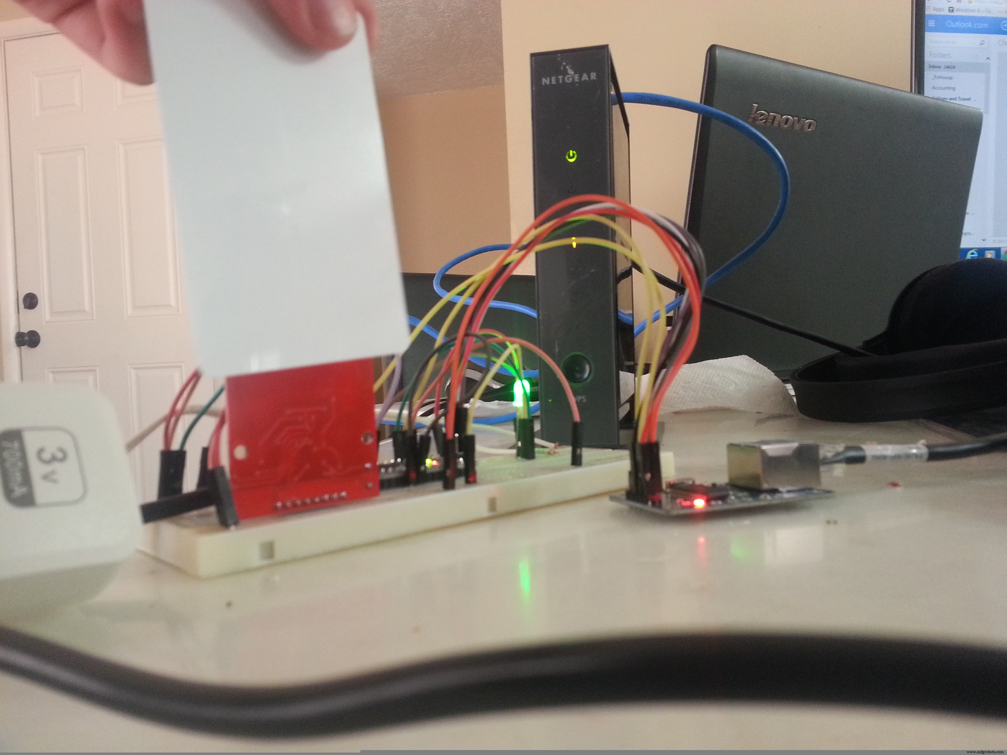
Here is the prototype:
You might be thinking it might take a long time, yatta yatta yatta. Yet this thing only took me about 6 hours (Because I had power issues), but this could take you about 30 minutes to setup like the example above. All the code and pictures are below so if you are confused in the next steps go ahead and look at the lower pictures/code.
Here are all the steps:
Before we Begin (Necessary)
Before we can start scanning cards and sending them to our Telnet/TCP server we need some libraries Get UIPEthernet here https://github.com/ntruchsess/arduino_uip
get MFRC522 here https://github.com/miguelbalboa/rfid
Put both of these libraries in Program Files(x86)/Arduino/Libraries/ Restart arduino
Hardware
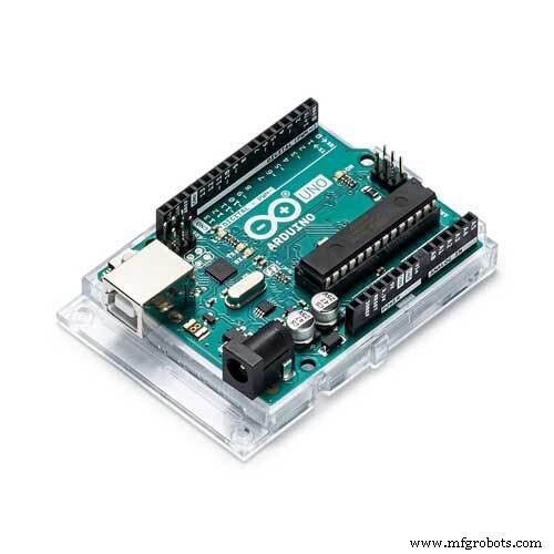
- Arduino Nano (You can always modify your code to fit your device)
- MFRC522 with MAIFARE cards
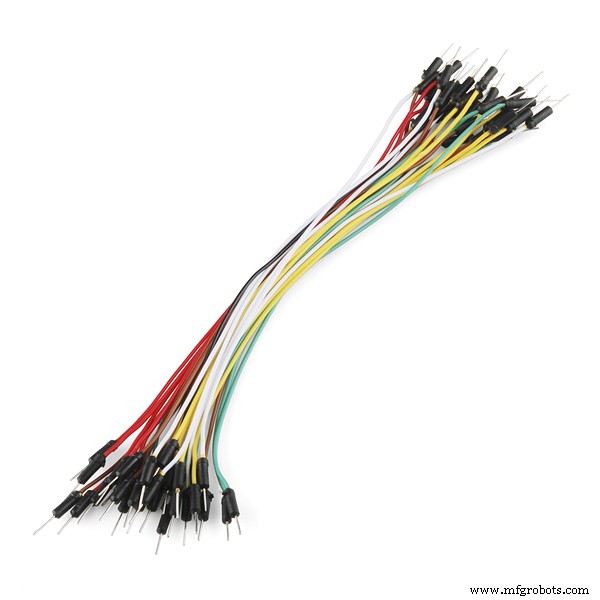
- Jumper wires (Male to Male) (Male to Female)
- enc28j60 ethernet module/sheild
- RGB LED
- 3V OR 5V greater than 700 mileamp AC-DC converter
Setup
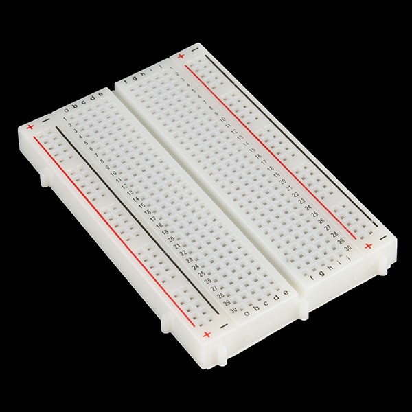
- Attach arduino to breadboard (If nano or micro)
- Look up online for the pinout of your board to find the SPI setup(Change values below)
- Connect arduino pin 10 (SS) to ethernet module ss or CS
- Connect arduino pin 12 (MISO) to rfid MISO and ethernet SO
- Connect arduino pin 11 (MOSI) to rfid MOSI and ethernet SI
- Connect arduino pin 13 (SCK) to rfid SCK and ethernet SCK
- Connect arduino pin 9 to rfid RST pin
- Connect arduino pin 8 to rfid SSN
- Connect arduino pin 5 to green led, 4 to blue and 3 to red
- Connect your AC to DC to the + and - on your breadboard
- Ground your arduino to the ac to dc
- Connect VCC and GND on both rfid and ethernet to the ac-dc (REMEMBER THESE DEVICES ARE ONLY 3v!!!!! do not supply 5v) If problem use resistors to bring the voltage to 3v
- Wire VCC pin on LED to the arduino 3v or ac-dc 3v
- Connect ethernet cable to module and make sure it is on the same network as your computer
- Plug USB cable from computer to arduino
- Connect computer to same network
Modify code to fit your needs
- The code is pretty well commented so you can just go in and modify certain parts but one thing for sure is the ehternet module
- Mac address can stay the same (Unless you're planning to build multiple of these)
- If you are using a 192.168. base ip network you can keep the ip
- Again you can keep the dns, only time to change is to 8.8.4.4
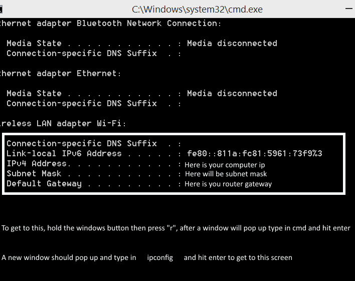
- run ipconfig to find your gateway, the default is 192.168.1.1 (if you don't know it) (The code currently is 192.168.1.5)
- run command prompt and type ipconfig to figure out your computers ip address
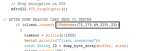
- scroll down to find SEND TO SERVER, and input the ip of your computer or if your port forwarded your router to your public ip address
- MAKE SURE YOU HAVE PYTHON AND RUN THE SERVER (Remember it's just an example code we used for our presentation to the school, so the python server was already premade and almost not modified you can use any Telnet/TCP server)
And the other code you will probably need to modify:
Running the code
- Plug AC-DC power to the wall
- Make sure your arduino is currently connected to the computer
- Make sure both device are on the same network
- Flash your modified arduino code or if the one I have works for you then great(Almost no chance you will have to modify it)
- Start your Python, C++ script or whatever Telnet/TCP server on your network
- Restart your arduino to be safe
- Wait until the light turns blue and try scanning a card, if your server got the ID of the card then your ready to go
- Remember what the lights means Purple/fading red means booting up
- Red means any error such as the card was at a weird angle and/or the server didn't respond in time
- Green means pass so the server responded with a go and you can read your next card
- Blue means waiting/loading waiting for a card or response
- If your arduino starts to lag out and takes over 30 seconds to show a red light means that the arduino ethernet module couldn't connect to the server at all. This could be caused by multiple things first your arduino doesn't have enough power and the arduino ethernet module is struggeling to send a packet or that your computer server isn't running or that your arduino and computer are not on the same network.
If your arduino keeps lagging out then try these tricks to fix them
Turn off windows firewall
- go into advanced firewall settings and allow inbound/outbound port 23
- port forward you router to your computer with port 23
- If you are wireless connect the arduino straight into the router and your computer to the same one
- Buy a more heavy duty AC-DC power adapter
Else maybe you input your ip address or connecting address wrong
Either than that contact me at smerkousdavid@gmail.com if there are any problems
- YOU'RE GOOD TO GO!!!
Remember there isn't any code for the door lock system, because I don't have one, this means you will have to add some code if you want to use this not only as a tracking system but as a door lock tracking system.
Please read below:
Code
- The Arduino code
- Example server code
The Arduino codeC/C++
This is the software goes on the arduino almost ready to go, so what you do is just adjust the gateway, ip, gateway, mac address, and dns/*
* ----------------------------------
* MFRC522 Arduino
* Reader/PCD Nano v3
* Signal Pin Pin
* ----------------------------------
* RST/Reset RST D9
* SPI SS NSS D10
* SPI MOSI MOSI D11
* SPI MISO MISO D12
* SPI SCK SCK D13
*/
// THE FIRST LIBRARY THAT NEEDS TO BE INSTALLED IS UIP ETHERNET SECOND IS MFRC522 BOTH ARE ON GITHUB
#include <UIPEthernet.h>
#include <SPI.h> //For the selection of the key
#include <MFRC522.h> //The RFID key library
#define RST_PIN 9 // Configurable, see typical pin layout above - This is for the Arduino Nano - For RFID
#define SS_PIN 8 //WE ARE USING 8 FOR RFID BECAUSE THE ETHERNET MODULE USES 10
byte sector = 0;
byte blockAddr = 0; ////////Access certain sector/blocks in the card, trailer block is the last block
byte trailerBlock = 1;
int red = 3;
int blue = 4; //Pins for RGB LED
int green = 5;
EthernetClient client; //ETHERNET INSTANCE
MFRC522 mfrc522(SS_PIN, RST_PIN); // Create MFRC522 instance.
MFRC522::MIFARE_Key key; //Set key instance
signed long timeout; //TIMEOUT SO IT DOESN'T SIT THERE FOREVER
void setup()
{
//UI BEGIN
pinMode(red, OUTPUT);
pinMode(blue, OUTPUT); //Init the RGB LED
pinMode(green, OUTPUT);
Reset(); //Start with leds off
Serial.begin(9600); //Start computer connection with a rate of 9600 bits per second
//UI END
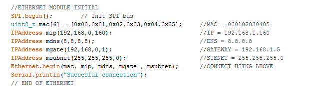
//ETHERNET MODULE INITIAL
SPI.begin(); // Init SPI bus
uint8_t mac[6] = {0x00,0x01,0x02,0x03,0x04,0x05}; //MAC = 000102030405
IPAddress mip(192,168,1,160); //IP = 192.168.1.160
IPAddress mdns(8,8,8,8); //DNS = 8.8.8.8
IPAddress mgate(192,168,1,5); //GATEWAY = 192.168.1.5
IPAddress msubnet(255,255,255,0); //SUBNET = 255.255.255.0
Ethernet.begin(mac, mip, mdns, mgate , msubnet); //CONNECT USING ABOVE
Serial.println("Succesful connection");
// END OF ETHERNET
for(int t = 255; t > 0; t--)
{
analogWrite(red, t); ////More of show but let at least a second between the SPI of the ethernet and RFID
delay(10);
}
//RFID INITIAL
mfrc522.PCD_Init(); // Init MFRC522 card
for (byte i = 0; i < 6; i++) { // Prepare the key (used both as key A and as key B)
key.keyByte[i] = 0xFF; // using FFFFFFFFFFFFh which is the default at chip delivery from the factory
}
Serial.println(F("Scan a Card"));
dump_byte_array(key.keyByte, MFRC522::MF_KEY_SIZE); //Get key byte size
timeout = 0;
delay(2000);
Reset();
}
//END RFID INITIAL
void loop() //Run forever
{
// Look for new cards
if ( ! mfrc522.PICC_IsNewCardPresent())
{
digitalWrite(blue, LOW);
return;
}
// Select one of the cards
if ( ! mfrc522.PICC_ReadCardSerial())
return;
digitalWrite(blue, HIGH); //Show user that card has been read
byte piccType = mfrc522.PICC_GetType(mfrc522.uid.sak);
// Check for compatibility with Mifare card
if ( piccType != MFRC522::PICC_TYPE_MIFARE_MINI
&& piccType != MFRC522::PICC_TYPE_MIFARE_1K
&& piccType != MFRC522::PICC_TYPE_MIFARE_4K) {
Error();
return;
}
byte status;
byte buffer[18];
byte size = sizeof(buffer);
status = mfrc522.PCD_Authenticate(MFRC522::PICC_CMD_MF_AUTH_KEY_A, trailerBlock, &key, &(mfrc522.uid));
if (status != MFRC522::STATUS_OK) {
Serial.print(F("PCD_Authenticate() failed: "));
Serial.println(mfrc522.GetStatusCodeName(status));
Error();
return;
}
// Read data from the block
status = mfrc522.MIFARE_Read(blockAddr, buffer, &size);
if (status != MFRC522::STATUS_OK) {
Serial.print(F("MIFARE_Read() failed: "));
Serial.println(mfrc522.GetStatusCodeName(status));
Error();
}
// Halt PICC
mfrc522.PICC_HaltA();
// Stop encryption on PCD
mfrc522.PCD_StopCrypto1();
// AFTER DONE READING CARD SEND TO SERVER
if (client.connect(IPAddress(192,168,1,100),23))
{
timeout = millis()+1000;
Serial.println("Client connected");
const String ID = dump_byte_array(buffer, size);
client.println(ID);
Serial.println("sent :" + ID);
delay(10);
while(client.available()==0)
{
if (timeout - millis() < 0)
goto close;
}
int size;
while((size = client.available()) > 0)
{
uint8_t* msg = (uint8_t*)malloc(size);
size = client.read(msg,size);
Serial.write(msg,size);
if(size == sizeof("g") - 1)
{
Pass();
}
else
{
Error();
}
free(msg);
}
close:
client.stop();
}
else
{
Serial.println("Couldn't connect to Server");
Error();
}
//END OF SENDING TO SERVER
Reset(); //RESTART LOOP WITH NO LEDS ON
}
// TURN THE BUFFER ARRAY INTO A SINGLE STRING THAT IS UPPERCASE WHICH EQUALS OUR ID OF THE SECTOR AND BLOCK
String dump_byte_array(byte *buffer, byte bufferSize) {
String out = "";
for (byte i = 0; i < bufferSize; i++) {
//Serial.print(buffer[i] < 0x10 ? " 0" : " ");
//Serial.print(buffer[i], HEX);
out += String(buffer[i] < 0x10 ? " 0" : " ") + String(buffer[i], HEX);
}
out.toUpperCase();
out.replace(" ", "");
return out;
}
//END DUMP_BYTE_ARRAY
//BELOW ARE THE LED METHODS
void Error()
{
digitalWrite(red, LOW);
delay(700);
digitalWrite(red, HIGH);
}
void Pass()
{
digitalWrite(green, LOW);
delay(700);
digitalWrite(green, HIGH);
}
void Reset()
{
digitalWrite(red, HIGH);
digitalWrite(blue, HIGH);
digitalWrite(green, HIGH);
}
//END OF FILE
Example server codePython
Here is a complete example of how to use the serverimport SocketServer
class MyTCPHandler(SocketServer.BaseRequestHandler):
def handle(self):
# self.request is the TCP socket connected to the client
self.data = self.request.recv(1024).strip()
print "{} wrote:".format(self.client_address[0])
print self.data
"""
SQL STUFF HERE
if(self.data == SQL NAME or something)
{
self.request.sendall("g")//send good
//INSERT TIME AND LOCATION INTO SQL HERE
{
else
{
self.request.sendall("bb")//send bad
//DO NOTHING just send to arduino bad data
}
"""
self.request.sendall("g")
if __name__ == "__main__":
HOST, PORT = "", 23
server = SocketServer.TCPServer((HOST, PORT), MyTCPHandler)
server.serve_forever()
Updated code on GitHub
Here you can get the most updated codehttps://github.com/smerkousdavid/InternetRFIDTagsSchematics
The circuit is simple so i just made a photo with the wiring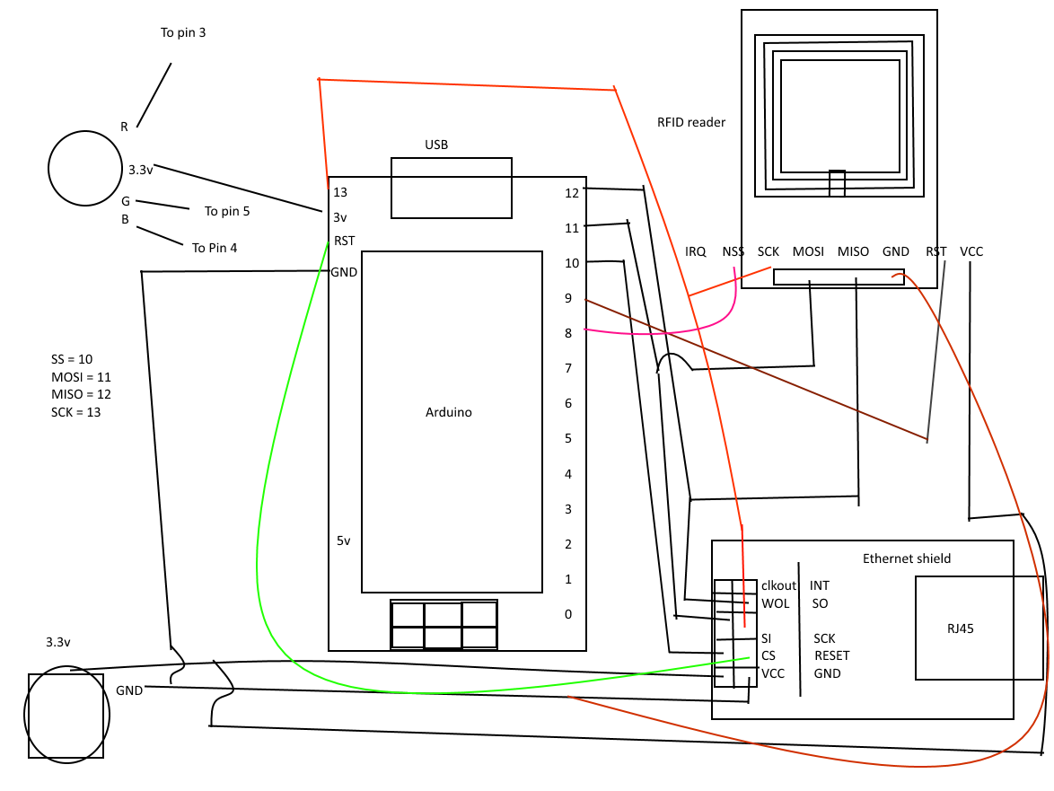
Manufacturing process
- Build a Secure Arduino RFID Door Lock with RC522 (MIFARE 13.56 MHz)
- Create a Secure Arduino RFID Lock – Step‑by‑Step Guide
- Mastering DC Motor Control: Expert Tips & Tricks
- Build a Portable RFID Door Lock with Arduino – Step-by-Step Guide
- Arduino-Based Amiga Floppy Disk Reader: Affordable Open-Source Data Recovery
- Accurate AC Current Measurement with the ACS712 Sensor on Arduino
- Integrate HID Prox RFID with Arduino UNO – Step‑by‑Step Setup
- Arduino-Based Amiga Floppy Disk Reader & Writer – Version 2.2
- Arduino Data Logging with SD Card & DS3231 RTC – Step‑by‑Step Tutorial
- Control Any Device with Your TV Remote Using Arduino IR – Step-by-Step Tutorial