


Arduino Data Logging with SD Card & DS3231 RTC – Step‑by‑Step Tutorial
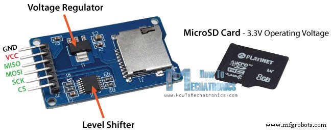
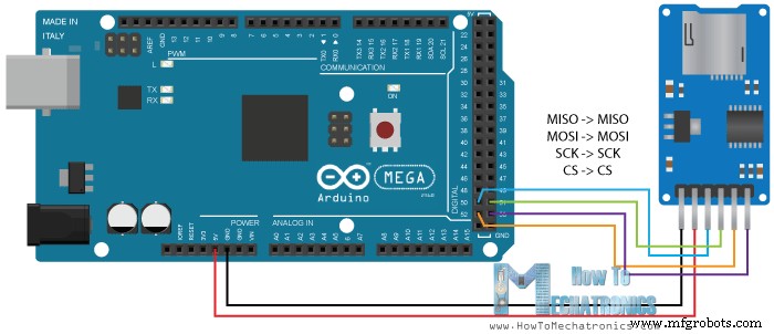
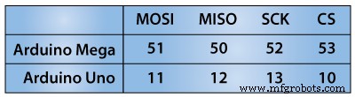
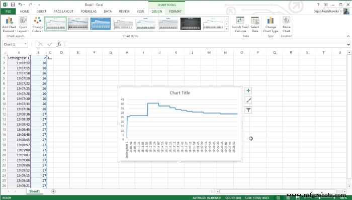
In this Arduino Tutorial we will learn how to use an SD Card module with the Arduino Board. Also in combination with the DS3231 Real Time Clock module we will make a data logging example where we will store the data of a temperature sensor to the SD Card and import it into Excel to make a chart out of it. You can watch the following video or read the written tutorial below. First let’s take a look at the SD Card Module. It works with standard MicroSD Cards which operating voltage is 3.3 V. Therefore, the module has a voltage regulator and a level shifter so that we can use it with the 5 V pins of the Arduino Board. The SD Card Module have six pins, two for powering the module, the VCC and the GND pins, and four more pins for the SPI communication. Here’s how we need to connect it to the Arduino Board. Note that each Arduino Board have different SPI pins which should be connected accordingly. You can get the components needed for this Arduino Tutorial from the links below: Next we need to program the Arduino. Here’s a simple code: Code description: So first we need to include the standard SD and SPI libraries, create a “File” object and define the ChipSelect pin of the SPI bus, the pin 53 in my case for the Arduino Mega Board. For this example we want our code to be executed only once, so all the code will be placed in the “setup” section, while the “loop” section will remain empty. So first we need to start the serial communication and define the ChipSelect pin as output. We have to do this because the ChipSelect pin needs to be “Low” so that the SPI communication between the module and the Arduino works. Next, using the SD.begin() function we will initialize the SD card and if initialization is successful the “if” statement will become true and the String “SD card is ready to use.” will be printed on the serial monitor, else the string “SD card initialization failed” will be printed and also the program will be terminated. Next, using the SD.open() function we will create a new file named “test.txt”, including the FILE_WRITE argument meaning that we can both read and write to the file. If the file already exist the SD.open() function will just open it. So if the file has been successfully created first we will print the string “Writing to file” on the serial monitor and then using the myFile.println() function we will print the text “Testing text 1, 2 ,3…” into the file. After that we need to use close() function to ensure that the previous data written to the file is physically saved to the SD Card. Next, we will see how we can read from the file. So again we will the same function, SD.open(), but this time as the file “test.txt” has already been created, the function will just open the file. Then using the myFile.read() function we will read from the file and print it on the serial monitor. The read() function actually reads just one character at a time, so therefore we need to use the “while” loop and the function myFile.available() to read all characters or the whole previously written data. At the end we need to close the file. Now after uploading the code to the Arduino, if everything is ok, the following will appear on the serial monitor. As we can see, the SD card has been successfully initialized, the writing to it has been successful as well, and also reading the written data or the string “Testing text 1, 2 ,3…” has been successful read. If we open the SD card on our computer we can see the created “test.txt” file and the written text in it. Now let’s make another more interesting example of data logging a temperature sensor. For that purpose we will use the DS3231 Real Time Clock module which has a built-in temperature sensor as well. You can find more details about how to connect and use this module in my previous tutorial. So after connecting the two modules to the Arduino let’s take a look at the code for this example. Code Description: First we need to include the libraries needed for both modules, then create the two objects and in the setup section initialize them. In the loop section using the Serial.print() funtion we will print the time and the temperature values on the serial monitor, with a “comma” character between them and a new line after the temperature value. We need this form of the lines so that we can easily import them and make a chart in Excel. Also note that the temperature values are converted into integers. So these same values will also be written into the newly created “test.txt” file and at the end we just need to add a delay which will represent the interval of recording the temperature data. After uploading the code the Arduino will start storing the temperature values each 3 seconds.After a while we can open the SD card on our computer to see the results. For creating a chart in Excel we need to import this file and here’s how we will do that: From the data menu we need to click “Get Data From Text” button and select the text file. Here we will choose “Delimited” and click next, and in the second step, select the comma as delimiter and then finish the wizard. So this process will insert the time and the temperature values into separate columns. Now we just need to select both columns and from the insert menu select “Insert line chart”. This will create the chart where we can see the temperature values each 3 seconds. That’s all for this tutorial, feel free to ask any question in the comments section below.How It Works
Arduino SD Card Module Code
/*
 *  Arduino SD Card Tutorial Example
 *
 *  by Dejan Nedelkovski, www.HowToMechatronics.com
 */

#include <SD.h>
#include <SPI.h>

File myFile;

int pinCS = 53; // Pin 10 on Arduino Uno

void setup() {

  Serial.begin(9600);
  pinMode(pinCS, OUTPUT);

  // SD Card Initialization
  if (SD.begin())
  {
    Serial.println("SD card is ready to use.");
  } else
  {
    Serial.println("SD card initialization failed");
    return;
  }

  // Create/Open file
  myFile = SD.open("test.txt", FILE_WRITE);

  // if the file opened okay, write to it:
  if (myFile) {
    Serial.println("Writing to file...");
    // Write to file
    myFile.println("Testing text 1, 2 ,3...");
    myFile.close(); // close the file
    Serial.println("Done.");
  }
  // if the file didn't open, print an error:
  else {
    Serial.println("error opening test.txt");
  }

  // Reading the file
  myFile = SD.open("test.txt");
  if (myFile) {
    Serial.println("Read:");
    // Reading the whole file
    while (myFile.available()) {
      Serial.write(myFile.read());
   }
    myFile.close();
  }
  else {
    Serial.println("error opening test.txt");
  }

}
void loop() {
  // empty
}Code language: Arduino (arduino)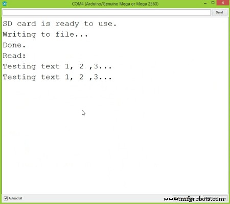
Arduino SD Card Data Logging
/*
 *  Arduino Temperature Data Logging
 *
 *  by Dejan Nedelkovski, www.HowToMechatronics.com
 */

#include <SD.h>
#include <SPI.h>
#include <DS3231.h>

File myFile;
DS3231  rtc(SDA, SCL);

int pinCS = 53; // Pin 10 on Arduino Uno

void setup() {

  Serial.begin(9600);
  pinMode(pinCS, OUTPUT);

  // SD Card Initialization
  if (SD.begin())
  {
    Serial.println("SD card is ready to use.");
  } else
  {
    Serial.println("SD card initialization failed");
    return;
  }
  rtc.begin();
}
void loop() {
  Serial.print(rtc.getTimeStr());
  Serial.print(",");
  Serial.println(int(rtc.getTemp()));

  myFile = SD.open("test.txt", FILE_WRITE);
  if (myFile) {
    myFile.print(rtc.getTimeStr());
    myFile.print(",");
    myFile.println(int(rtc.getTemp()));
    myFile.close(); // close the file
  }
  // if the file didn't open, print an error:
  else {
    Serial.println("error opening test.txt");
  }
  delay(3000);
}Code language: Arduino (arduino)
Manufacturing process
- Arduino Temperature & Humidity Logger Using DHT11 and Ethernet Shield
- Arduino-Based Pressure Sensor & Data Logger for Accurate Air Pressure Monitoring
- Master the MPU6050: Accelerometer & Gyro Tutorial for Arduino
- Mastering Arduino with DS3231 RTC: Step‑by‑Step Tutorial
- Master Arduino Bluetooth: HC‑05 Module Tutorial for Smartphone & PC Control
- Mastering I2C Communication with Arduino: A Practical Tutorial
- Master Arduino Control with MATLAB GUI: Step-by-Step Tutorial
- Master Arduino & MATLAB Integration: Step‑by‑Step Serial Communication Tutorial
- Arduino Tutorial 06: Connecting Arduino to Processing via Serial Communication
- Arduino Tutorial 02: Buttons & PWM – Master Digital I/O & LED Control