


IoT Water Quality Sensor System - Arduino Based Real-Time Monitoring
Components and supplies
 |
| × | 1 | |||
 |
| × | 1 | |||
 |
| × | 1 | |||
 |
| × | 1 | |||
 |
| × | 3 | |||
 |
| × | 1 | |||
 |
| × | 1 | |||
|
| × | 1 |
Necessary tools and machines
 |
|
Apps and online services
 |
| |||
|
About this project
Water is an essential resource in our everyday lives. So, we must make sure it is of good quality for usage.
What is TDS?TDS stands for Total Dissolved Solids. As the name suggests, it gives us the number of solids dissolved in a certain amount of water, in ppm (parts per million). TDS is calculated based on electrical conductivity [S/m]. The higher the electrical conductivity, the higher the TDS value. Here is a list of the TDS values of different types of water:
- Pure water: 80-150
- Tap water: 250-350
- Groundwater: 500-1000
- Seawater: around 30000
As recommended by the WHO (World Health Organisation), the suitable TDS of drinking water is below 300. However, the water of TDS below 100 can't be consumed, as it would lack the essential minerals. Water above 300 is considered to be too "hard", as it contains more minerals than needed.
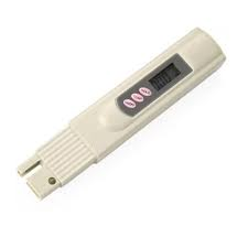
Normally, we use a TDS pen to measure the TDS of water. However, we can't integrate the pen with the Arduino. So, there are special TDS meters available that can be integrated with the Arduino. However,I have decided to do this project without the use of the TDS pen.
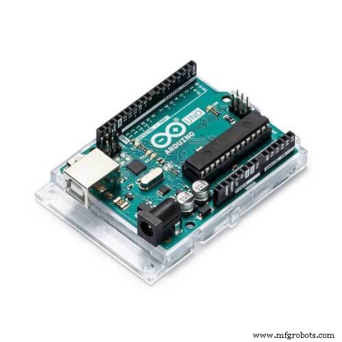
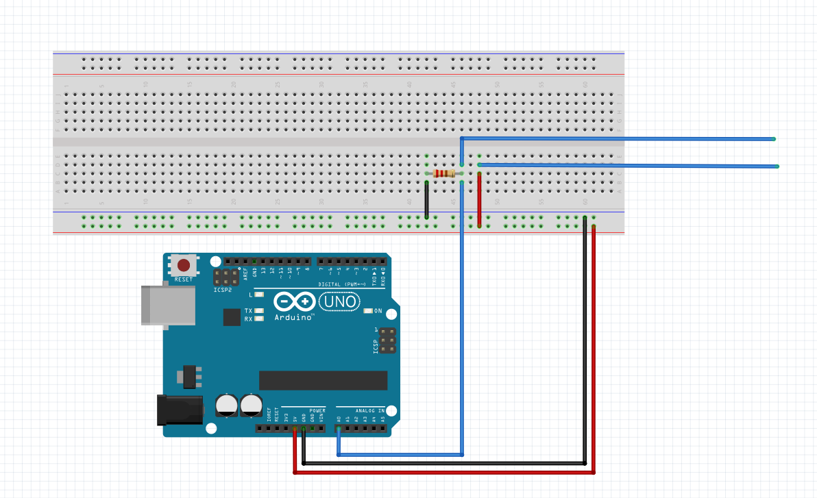
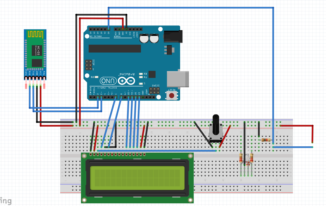
Arduino
- Connect 5V of Arduino to one power rail of the breadboard
- Connect the ground of Arduino to the other power rail of the breadboard
- Connect one end of a 1k-ohm resistor to the ground and the other end to the breadboard. Connect the analog pin A0 on the Arduino to the resistor. Finally, connect a wire to the resistor and another wire to 5V. Connect the free ends of these wires to the crocodile clips.
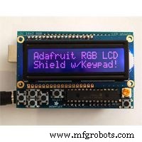
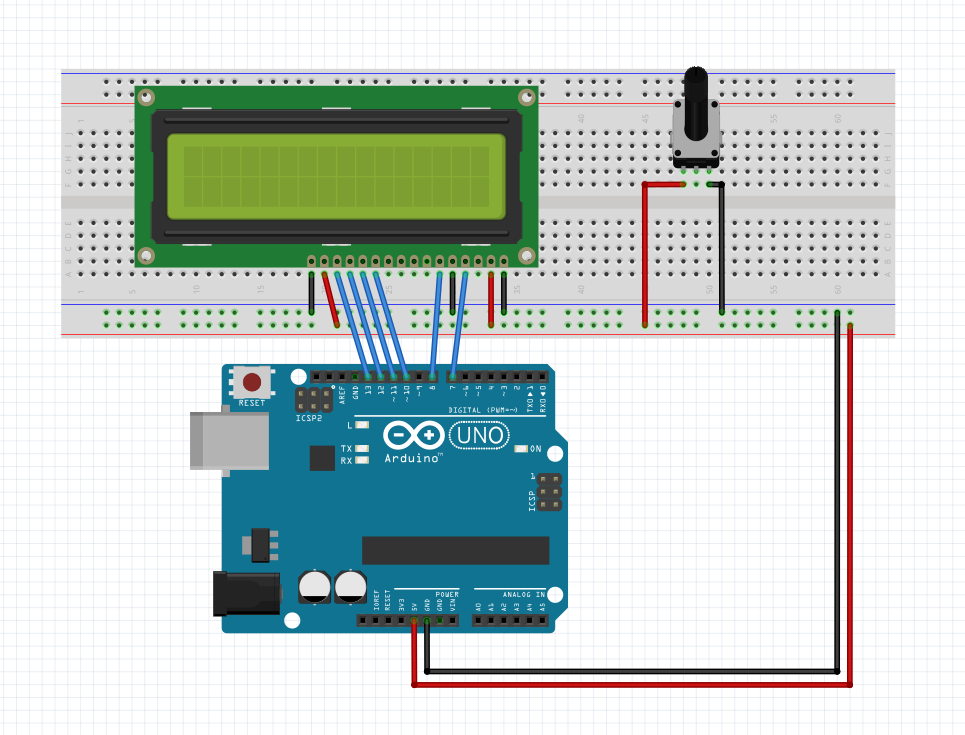
LCD Display
- Connect VSS pin to the ground rail
- Connect VDD pin to 5V rail
- Connect V0 to the centre pin of the potentiometer
- Connect ends of the potentiometer to 5V and ground
- Connect RS pin to Arduino pin 7
- Connect R/W pin to the ground rail
- Connect E pin to Arduino pin 8
- Connect D4 to Arduino pin 10
- Connect D5 to Arduino pin 11
- Connect D6 to Arduino pin 12
- Connect D7 to Arduino pin 13
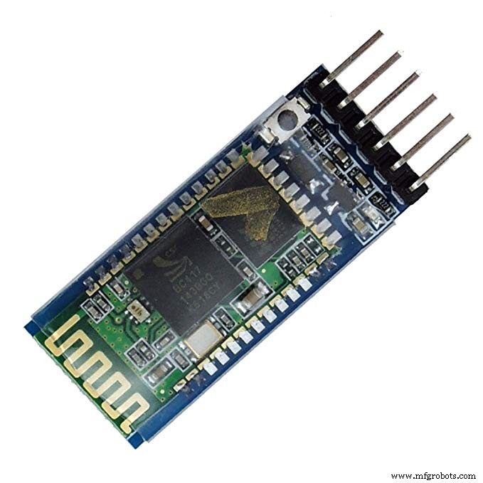
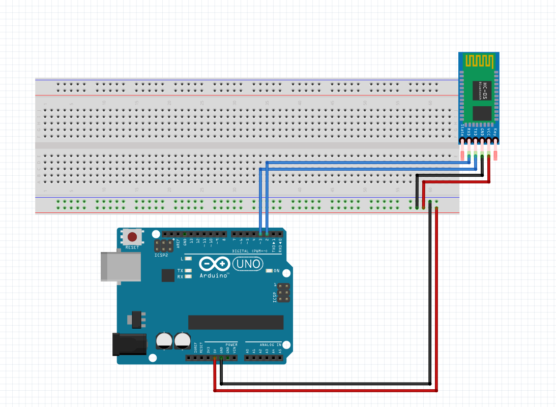
HC-05 Bluetooth module
- Connect VCC pin to 5V rail
- Connect GND pin to ground
- Connect TX pin to Arduino pin 3 (Serves as RX)
- Connect RX pin to Arduino pin 2 (Serves as TX)
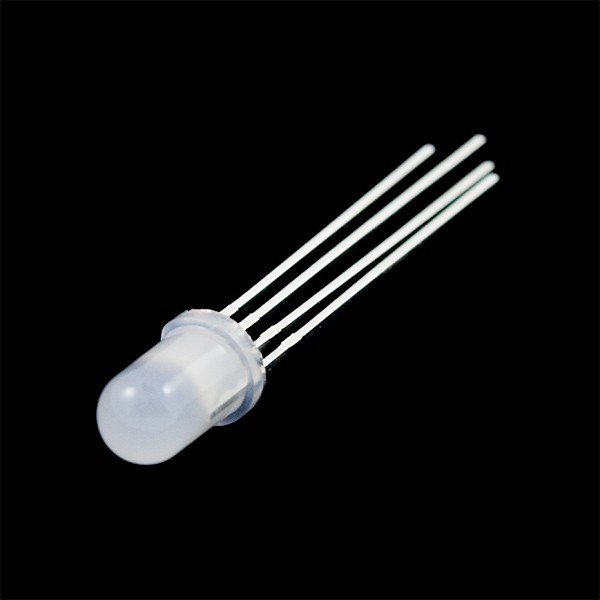
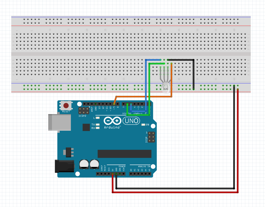
RGB LED
- Connect the common cathode (longest pin) to ground
- Connect the red pin (right of cathode pin) to PWM pin 9 on Arduino through a 330-ohm resistor
- Connect green pin (left of cathode pin) to PWM pin 6 on Arduino through a 330-ohm resistor
- Connect blue pin (extreme left) to PWM pin 5 on Arduino through a 330-ohm resistor
We will be using Ohm's law, which states that the voltage [V] through a resistor of resistance R is directly proportional to the current [I] flowing through the resistor. In other words, V = IR
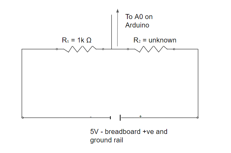
Although there is a wire connected between the 2 resistors [R₁ - 1000-ohm, and R₂ - between the free wires] to the Analog pin A0 on the Arduino, the resistance of that wire can be neglected, and hence, we can say that minimal current flows through the wire. So, R₁ and R₂ are connected in series.
So, we can say that V₁ = IR₁ and V₂ = IR₂.
Therefore, we can say V₂/V₁= IR₂/IR₁ =R₂/R₁
. However, we do not know V₂.
We know that in a series combination of resistors, V₁+V₂ = V, where V = 5 Volts. From this, we can get V₂ = 5-V₁
Finally, substituting the value we got for V₂ in V₂/V₁ = R₂/R₁, we can define a variable buffer to be 5-V₁/V₁, instead of V₂/V₁.
Finally, we can say that R₂ = buffer * R₁.
We will calculate the resistance of the water under test, and from that, we will obtain the resistivity. We have to consider the length and the cross-sectional area of our container for this.
R = r L/A
=> r = R A/L
From the resistivity, we can obtain the conductivity
c = 1/r
Finally, we obtain the TDS from the conductivity
TDS = c*7000
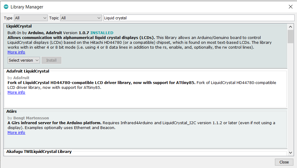
- Liquid crystal library: https://www.arduinolibraries.info/libraries/liquid-crystal
- Software serial library: https://pdfpunk.weebly.com/softwareserial-library-download.html
You can either download these libraries and add them to your Arduino IDE, or you can go to Tools -> manage libraries -> search for the library you want to download

Code
- Water quality monitoring code
Water quality monitoring codeArduino
//include libraries
#include <SoftwareSerial.h>
#include <LiquidCrystal.h>

//for bluetooth - create an object called BTserial, with RX pin at 3 and TX pin at 2
SoftwareSerial BTserial(3,2); // RX | TX

//decraration of all our variables

float reads;
int pin = A0;

float vOut = 0 ;//voltage drop across 2 points
float vIn = 5;
float R1 = 1000;
float R2 = 0;
float buffer = 0;
float TDS;

float R = 0;//resistance between the 2 wires
float r = 0;//resistivity
float L = 0.06;//distance between the wires in m
double A = 0.000154;//area of cross section of wire in m^2

float C = 0;//conductivity in S/m
float Cm = 0;//conductivity in mS/cm

int rPin = 9;
int bPin = 5;
int gPin = 6;
int rVal = 255;
int bVal = 255;
int gVal = 255;

//we will use this formula to get the resistivity after using ohm's law -> R = r L/A => r = R A/L

//creating lcd object from Liquid Crystal library
LiquidCrystal lcd(7,8,10,11,12,13);

void setup() {
  //initialise BT serial and   serial monitor
  Serial.begin(9600);
  BTserial.begin(9600);

  //initialise lcd
  lcd.begin(16, 2);

  //set rgb led pins (all to be pwm pins on Arduino) as output
  pinMode(rPin,OUTPUT);
  pinMode(bPin,OUTPUT);
  pinMode(gPin,OUTPUT);
  pinMode(pin,INPUT);
  //Print stagnant message to LCD
  lcd.print("Conductivity: ");
}

void loop() {
    reads = analogRead(A0);

  vOut = reads*5/1023;
  Serial.println(reads);
//  Serial.println(vOut);
  buffer = (vIn/vOut)-1;
  R2 = R1*buffer;
  Serial.println(R2);
  delay(500);
    //convert voltage to resistance
    //Apply formula mentioned above
      r = R2*A/L;//R=rL/A
    //convert resistivity to condictivity
    C = 1/r;
    Cm = C*10;
    //convert conductivity in mS/cm to TDS
    TDS = Cm *700;
    //Set cursor of LCD to next row
    lcd.setCursor(0,1);
    lcd.println(C);

    //display corresponding colours on rgb led according to the analog read
     if( reads < 600 )
  {
      if (reads <= 300){
        setColor( 255, 0, 255 ) ;
      }
      if (reads > 200){
        setColor( 200, 0, 255 ) ;
      }
  }
  else{
    if( reads <= 900 )
    {
      setColor( 0, 0, 255 ) ;
    }
    if( reads > 700 )
  {
    setColor( 0, 255, 255 ) ;
  }
    }

//send data to Ardutooth app on mobile phone through bluetooth
BTserial.print(C);
BTserial.print(",");
BTserial.print(TDS);
BTserial.print(";");
delay(500);
}


void setColor(int red, int green, int blue)
{
  analogWrite( rPin, 255 - red ) ;
  analogWrite( gPin, 255 - green ) ;
  analogWrite( bPin, 255 - blue ) ;
}
Custom parts and enclosures
I used an old test tube I had to make this. I poked holes on either end of the tube and inserted wires from either end. Finally, to hold the wires in place, I attached some putty.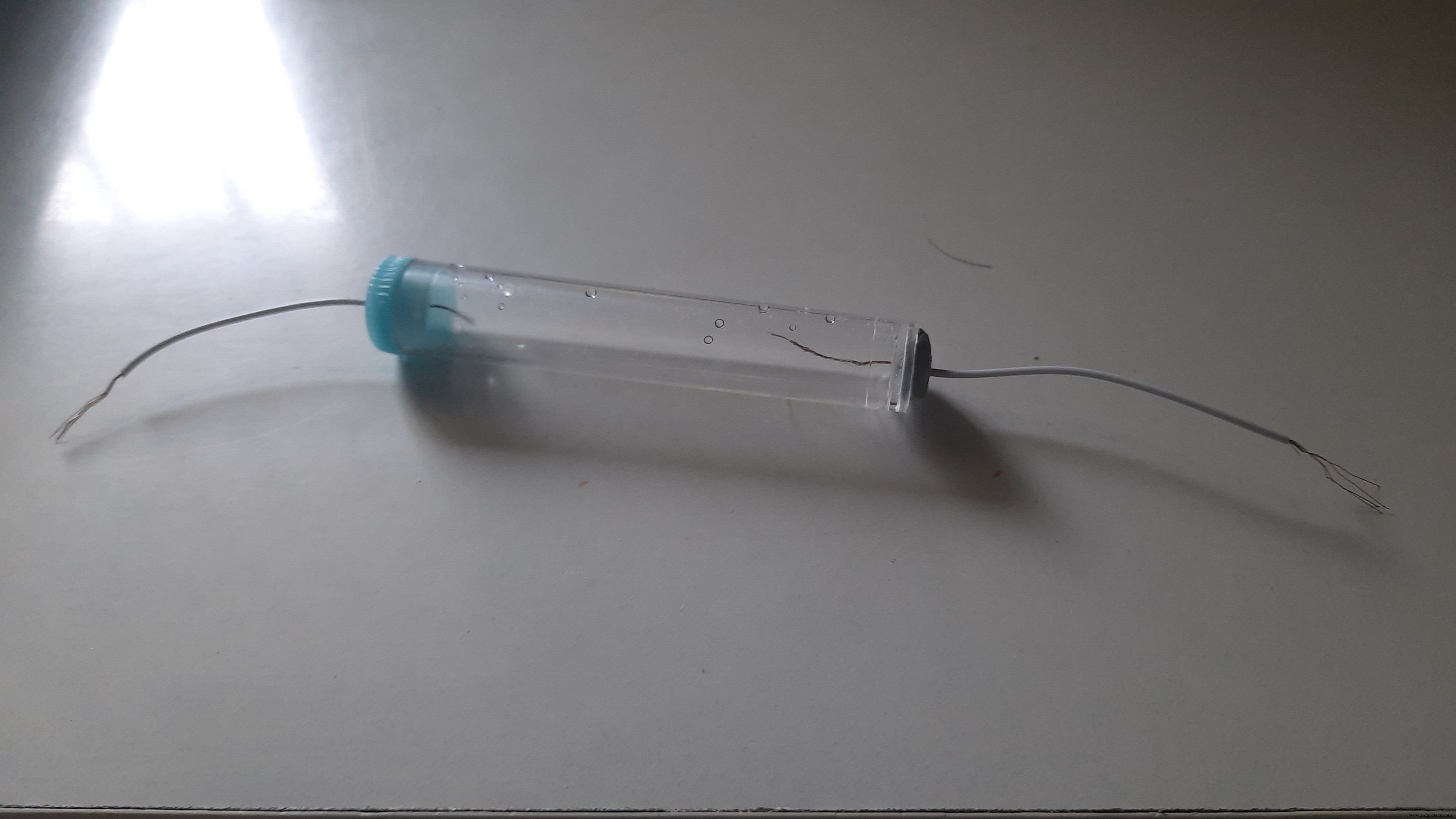
Schematics
Manufacturing process
- Multi‑Position Temperature Sensor System for Smart Home Integration
- Smart Arduino Water Bottle – Real-Time Monitoring & Alerts
- Arduino Nano Weather Station: Sensor Kit & OLED Display
- Build an Arduino‑Based Air Quality Monitor Using the DSM501A Dust Sensor
- Build a Smart Wristband with Arduino MKR GSM 1400 & Hologram IoT
- Arduino-Based Indoor Air Quality & Comfort Sensor Kit
- Real‑Time Water Quality Monitoring System with Arduino & GPRS/GPS
- Harnessing IoT to Protect Water Quality and Combat Air Pollution
- Unlock Real-Time Water Quality Insights with IoT Monitoring
- Advanced Carbon‑Based NO₂ Sensor Enhances Indoor Air Quality Monitoring