


Draw Bridges: Engineering, History, and Modern Innovations
Background
A bridge over a navigable waterway must allow vessels to pass beneath it. When the required clearance cannot be achieved by building a high fixed bridge—due to steep approaches, visual impact, or budget constraints—a movable bridge provides a practical solution. The most common movable bridge is the bascule, a seesaw‑style structure that lifts one or two leaves. Other types include vertical lift spans, retractable bridges, and swing bridges, each designed to accommodate different site constraints and traffic demands.
Movable bridges are comparatively rare because they require more complex operations and maintenance. They also temporarily disrupt both waterborne and land traffic. Of the 770 bridges managed by the New York City Transportation Department, 25 are movable, covering all four principal types.
History
Early examples date back 4,000 years in Egypt and 2,600 years in the Chaldean kingdom. The design gained prominence in Europe during the Middle Ages, and by the late fifteenth century Leonardo da Vinci had already produced plans for bascule, swing, and retractable bridges.
The modern era began in the mid‑nineteenth century with mass‑produced steel, enabling stronger, lighter bridges with reliable bearings and powerful motors.
Most U.S. movable bridges were constructed in the early twentieth century. Today, refurbishment and replacement projects often incorporate higher clearances—reducing the frequency of openings to one‑quarter or one‑third of the original schedule—and hydraulic actuation instead of gear drives.
Raw Materials
Draw bridges rely primarily on concrete and steel. For example, the Casco Bay Bridge in Portland, Maine, used 750 short tons (6,804 metric tons) of structural steel and 150,000 short tons (13,608 metric tons) of concrete. The bridge features a 360‑foot (10‑nm) tall opening and opened in 1997.
Design
Each draw bridge is a unique structure tailored to its site and traffic profile. The most prevalent configuration is the bascule, which may be single‑leaf, double‑leaf, or four‑leaf (two leaves per direction). Counterweights offset the weight of the leaves, drastically reducing the energy required for operation.
Typical counterweight arrangements involve a massive concrete box that houses adjustable metal rods, allowing fine‑tuning of the balance. For instance, the Casco Bay Bridge’s 500‑ton (450‑metric‑ton) leaves are balanced by an 800‑ton (720‑metric‑ton) counterweight.
Key structural components include the trunnion—often a 10‑ft (3‑m) diameter steel shaft—and the lift mechanism, usually a rack‑and‑pinion gear set powered by electric motors.
The Manufacturing Process
While each project is distinct, the following steps outline the construction of a typical bascule bridge.
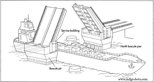
Piers
- For water‑borne piers, a cofferdam is erected around the site. Steel panels form a watertight box, and a clamshell digger removes soil. Piles—steel or reinforced concrete—are driven or poured deep into the riverbed. The cofferdam’s base is sealed with concrete, and water is pumped out to provide a dry work area.
- Concrete forms are constructed, and a reinforced concrete cage is placed inside. After pouring and curing, the forms are removed. Near the waterline, an erosion‑resistant layer such as granite may be applied before the cofferdam is dismantled.
- Fender systems protect the piers from vessel impacts. At Casco Bay, large concrete cylinders support steel fenders faced with slip‑resistant plastic and rubber bumpers to absorb shocks.
Bascule Leaves
- Trunnions are mounted on pier supports.
- A counterweight is positioned inside the pier.
- Gear drives or hydraulic lifts are installed.
- Side girders form the heel section; a trunnion bearing sits in each girder, and gears or hydraulic paddles connect to the lift mechanism.
- Girders are lifted into place and connected by a crossbeam, securing the counterweight to the heel.
- Longitudinal girders are added between the side girders, with steel braces providing additional support. As each component is added, the counterweight is adjusted to maintain balance.
- A tip section links the side girders at the leaf’s far end. Span locks secure opposite leaves when the bridge is closed, preventing bounce and locking them in the open position to resist wind.
Finishing
- Steel‑grate decking is laid over the leaf; a thin concrete layer may be added for smoothness.
- Final balancing is achieved by inserting heavy rods—steel, iron, or lead—into counterweight compartments. Proper balance results in a slight weight advantage for the leaf, allowing gravity to close the bridge gently.
Ongoing Adjustments
Counterweight tuning is necessary throughout a bridge’s life. Short‑term adjustments address seasonal ice or snow loads, while long‑term changes compensate for alterations such as repaving or painting. The High Street Bridge in Alameda County, California, shed 25,000 lb (11,000 kg) of paint during a 1996 refurbishment, requiring counterweight recalibration before and after repainting.
In 1992, a malfunction at Chicago’s Michigan Avenue Bridge caused a catastrophic failure: a partially opened leaf, unbalanced by the removal of paving, unexpectedly sprang up, launching debris onto Wacker Drive and injuring six people. The incident underscored the critical importance of accurate counterweight maintenance and reliable safety locks.
The Future
Innovation in movable bridges falls into two categories. Refinements of traditional designs minimize the need for large, submerged counterweight pits. For example, the 17th Street Causeway Bridge in Fort Lauderdale, Florida, employs compact counterweights that swing within V‑shaped piers. The South Eighth Street Bridge in Sheboygan, Wisconsin, operates without counterweights, using a powerful hydraulic system instead.
New concepts are also emerging. The Baltic Millennium Bridge in Gateshead, England—expected to open in 2001—features two parabolic arches linked by cables. When closed, one arch is horizontal and the other vertical; when opened, both rotate to a 45° angle, rising to 164 ft (50 m) above water. The lightweight steel‑aluminum structure supports pedestrian and bicycle traffic across a 410‑ft (125‑m) span.
Manufacturing process
- How Bridges Stabilize Overhangs in 3D Printing
- Full-Wave Bridge Rectifier: Design, Benefits, and Practical Implementation
- Bridge Circuits: Wheatstone, Kelvin, and Their Role in Precise Electrical Measurements
- AC Bridge Circuits: Precise Impedance Measurement with Balanced Ratios
- Suspension Bridges: Design, History, and Engineering Excellence
- Concrete Beam Bridge: Design, Construction, and Future Trends
- Linearizing Resistive Sensor Bridges with Two Proven Hardware Methods
- AIT Bridges Launches Advanced Composite Tub Girder System
- Understanding Pedestrian Bridges: Purpose, Design, and Safety
- Designing Pedestrian Bridges with Structural Steel: A Modern Construction Approach