


Bar Code Scanner: Technology, Design, and Future Trends
Background
Bar code scanners have evolved from simple handheld wands to sophisticated, laser‑driven, holographic devices. At their core, all scanners translate the pattern of black and white stripes into a digital signal that a computer can interpret. The process relies on the differential reflectance of black (minimal light) and white (strong reflectance) bars. By illuminating the code and detecting reflected light, the scanner converts the pattern into an electrical signal for the host system.
First introduced in the early 1970s, bar codes accelerated data entry for warehouses, retail, airlines, libraries, and supermarkets. The technology eliminated manual keying, reduced errors, and enabled real‑time inventory and billing. Supermarket point‑of‑sale scanners represent the most demanding application, needing to read irregular, dirty, or fragile items in seconds.
Early devices, such as the wand scanner, required physical contact with the code and relied on a narrow light beam. This design was inexpensive but limited when codes were uneven or contaminated. The breakthrough came with laser illumination, which produced a focused, bright beam that could be swept over a surface without contact. Mid‑1970s motorized mirror assemblies allowed the laser to scan automatically, increasing speed and reliability.
Holographic technology replaced rotating mirrors in 1980. By embedding holograms on a spinning disk, scanners could reflect light in multiple directions from a single source. IBM and NEC independently introduced holographic point‑of‑sale scanners that could read codes from varied angles, dramatically improving user experience and throughput.
Raw Materials
A typical holographic scanner comprises a helium‑neon (HeNe) laser, high‑quality lenses, mirrors, and a photodiode detector. HeNe lasers emit a stable red beam that is easy to detect and cost‑effective. Photodiodes—commonly silicon or germanium—convert reflected light into electrical pulses.
The housing is usually stainless steel with an optical window made of glass or durable plastic. The window must remain transparent and dust‑free; any defect can scatter light and degrade accuracy.
Holographic disks are fabricated from dichromated gelatin (DCG) sealed between two plastic layers. DCG, a light‑sensitive material, is co‑developed by Dow Chemical and Polaroid. The disk contains 7–16 wedges, each engineered to reflect light at a specific angle, allowing the scanner to read codes from multiple orientations.
The spinning motor is a compact electric cylinder that turns the disk. It is attached to a central shaft and is designed for long life and precise speed control.
Design
The design phase involves laser engineers, optical designers, electrical engineers, and software developers. Key considerations include:
- Hologram efficiency: maximizing reflected light while maintaining a narrow beam.
- Scan pattern: ensuring high readability across a wide range of orientations.
- Laser power: balancing longevity, efficiency, and user safety.
- Optical throw: determining the maximum distance at which a code can be read accurately.
- Mechanical layout: positioning the spinning disk and optical components to fit within a compact, ergonomic housing.
- Signal processing: converting ON/OFF light pulses into binary data that the host system can decode.
The Manufacturing Process
After design, components are fabricated and assembled. The holographic disk is produced in‑house; lenses, mirrors, and lasers are sourced from specialized manufacturers and rigorously tested.
Hologram Disk
- Master disks are created by recording each wedge on a DCG sandwich. Each wedge reflects a distinct angle.
- After recording, wedges are glued onto a single transparent plate. Glycerin‑based adhesives are used to preserve optical fidelity.
- Replication uses optical copying: a laser projects the master onto a blank DCG disk, transferring the pattern.
Lenses, Mirrors, Laser
- These parts are verified against specifications upon arrival. Lifetime tests ensure reliability.
Housing
- Housing is either fabricated by a metal shop or built in‑house, then machined to exact tolerances.
- Strength and durability are validated through stress tests.
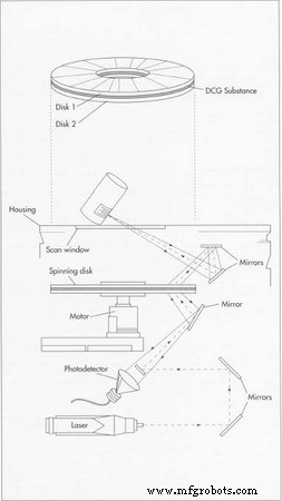
A laser beam illuminates the code, the reflected light is captured by a spinning holographic disk, and a photodetector translates the pattern into an electrical signal for the computer. Each disk contains 7–12 wedges, each reflecting light at a distinct angle. Production begins with a master disk; a single laser then transfers the pattern onto a blank DCG disk adjacent to the master.
Final Assembly
- The disk and motor are integrated and tested for scanning speed, pattern, and direction.
- The optical system—laser and mirrors—is mounted, ensuring optimal beam alignment.
- Once the unit passes all inspections, it is sealed within the housing and fitted with the scanning window.
Quality Control
Manufacturers adhere to industry benchmarks such as First Pass Read Rate (FPRR), Rejection Rate, and Read Velocity. Typical metrics:
- FPRR: the percentage of codes read correctly on the first pass.
- Rejection Rate: the number of scans per million that are unrecoverable.
- Read Velocity: the range of speeds at which codes can be reliably scanned.
Mechanical tests run units for days, sometimes years, to confirm consistent motor speed and torque. Optical tests verify reading consistency; a well‑built scanner should exceed 85% accuracy, though 75–85% is common.
Electrical tests evaluate the Rejection Rate. Scanners typically sample 100–200 scans per second, cross‑checking readings to tolerate imperfect prints. If a scanner fails these checks, it is sent for optical or electronic inspection.
The Future
Emerging trends include:
- Miniaturized semiconductor lasers, making wand scanners cheaper and more versatile.
- Interactive bar code toys and educational tools that replace buttons with scanning.
- Home‑shopping platforms that let consumers scan catalog items using a smartphone or handheld scanner linked to a modem.
- Advanced laser scanners for complex manufacturing workflows, tracking custom lots, and monitoring production stages.
- New optical assemblies that offer greater flexibility in size and application.
Manufacturing process
- CT (CAT) Scanners: Evolution, Design, and the Future of 3‑D Medical Imaging
- C++ Comments: Best Practices for Readable, Maintainable Code
- Wireless IR Temperature Scanner – Arduino Nano with Bluetooth & MLX90614
- EL Tape Music Visualizer – Illuminate Your Sound with Arduino
- Build a Morse Code Transceiver with Arduino UNO – Hands‑On Communication Project
- Arduino LED Bar Graph Controlled by Potentiometer
- How Barcode Scanners Influence Scan Range and Accuracy
- Norman Joseph Woodland, Co‑Inventor of the Barcode, Passes Away at 91
- Alloy 52 Bar: High-Performance Nickel-Iron Steel with Superior Strength
- Pneumatic Bar Feeders: The Cost‑Effective Solution for CNC Lathe Automation