


Arduino‑Powered Smart Pull‑Up Bar with Audio Feedback and Light Sensor
Components and supplies
 |
| × | 1 | |||
| × | 1 | ||||
| × | 1 | ||||
| × | 1 | ||||
| × | 1 | ||||
 |
| × | 1 | |||
 |
| × | 1 | |||
| × | 1 | ||||
| × | 1 | ||||
 |
| × | 1 | |||
 |
| × | 1 | |||
| × | 1 | ||||
 |
| × | 2 | |||
 |
| × | 3 | |||
 |
| × | 4 | |||
| × | 1 | ||||
| × | 1 | ||||
| × | 1 | ||||
| × | 1 | ||||
| × | 1 | ||||
| × | 1 |
Necessary tools and machines
 |
| |||
 |
|
Apps and online services
 |
|
About this project
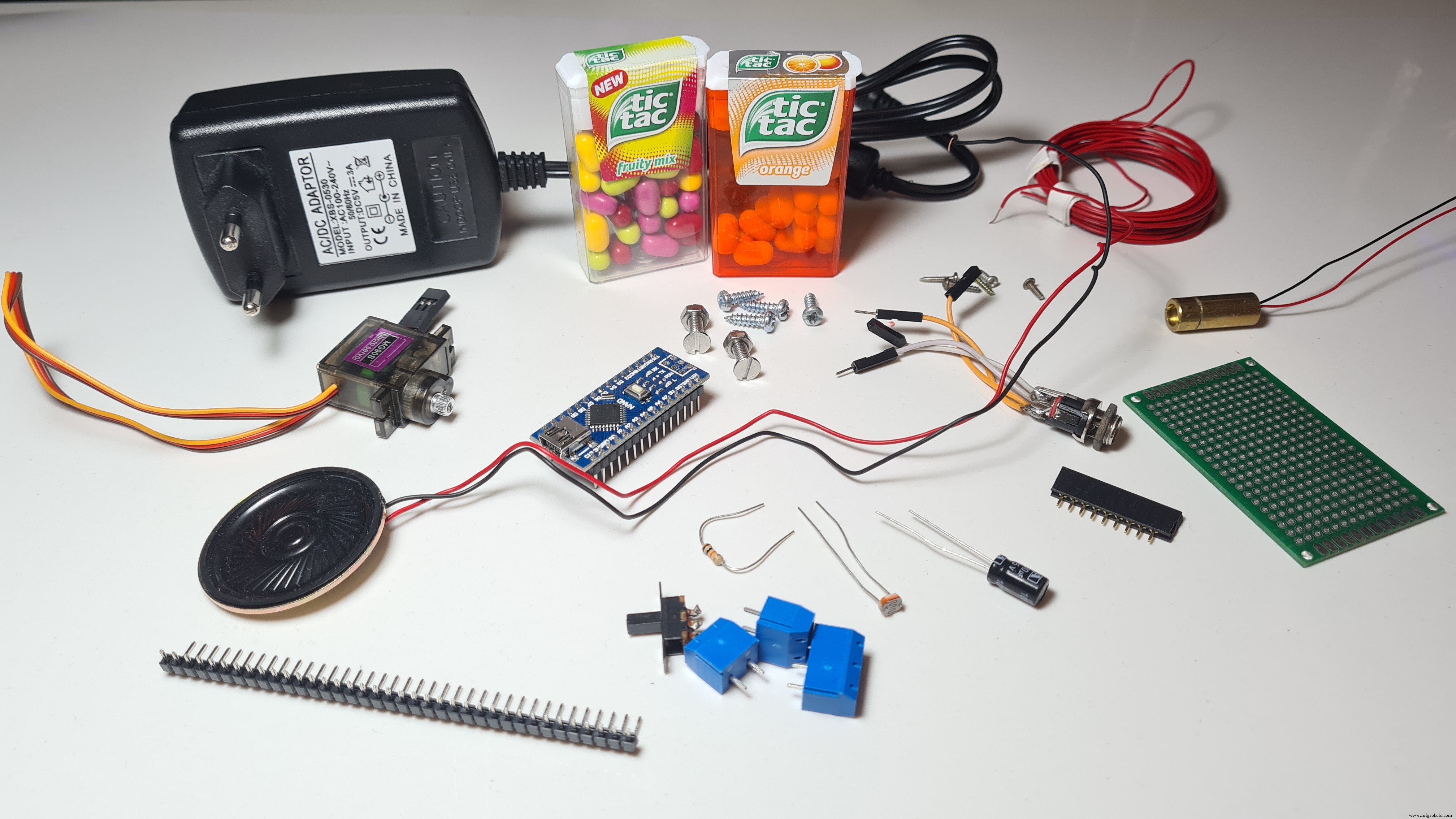
Hello friends! My name is Nikolas and I am 15 years old. Today in this tutorial I'll show you how to make a Smart Pull-Up Bar using an Arduino Nano which, when you start doing Pull-Ups or Chin-Ups starts playing music in order to keep you motivated and after exercising for a certain period, a reward, a Tic Tac, in my instance gets dispensed! Make sure to watch the YouTube video above to see the Smart Pull-Up Bar in action and to follow the instructions from there if you prefer!
I originally thought of making this to motivate me to work out more, but it turns out I just wanted an excuse to eat more candy!
Also I would really like to thank Arduino as this project was selected as one of the winners of the Arduino Day Community Challenge 2021!
Step 1: Understand How It Works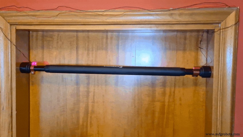
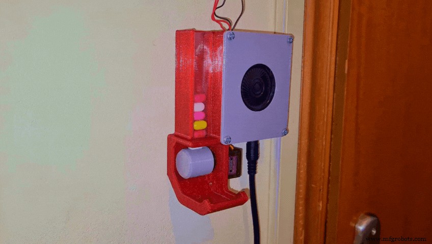
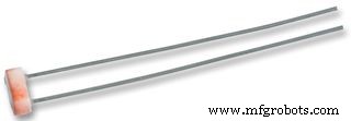
Basically I've made a Laser beam sensor by attaching a cheap Laser Diode and an LDR on the Pull-Up Bar. They are perfectly aligned which means that a lot of light reaches the LDR and thus the sensor outputs a high analog value. However once I place my hands on the bar to start working out I block the light beam, the value gets significantly lower and the sensor sends a signal to the Arduino Nano, which is mounted on the wall in an enclosure and then a song starts playing using a small speaker (In my case it was Take on me by A-ha). After around 30 seconds, when the song ends, if I still have my hands on the bar, a reward, a Tic Tac gets dispensed using a 3D printed mechanism that's rotated by a servo!
Now that you get how it works let's start making it!
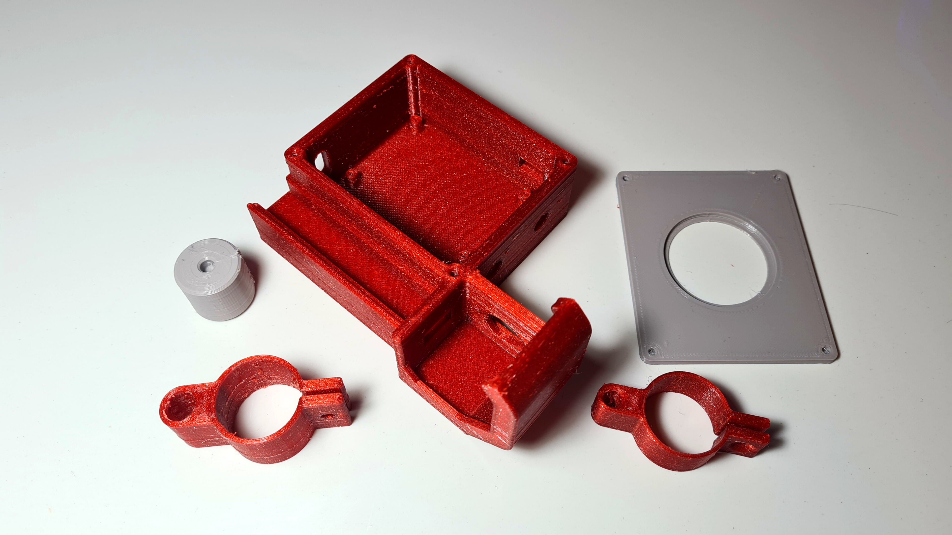
Step 2: 3D Printing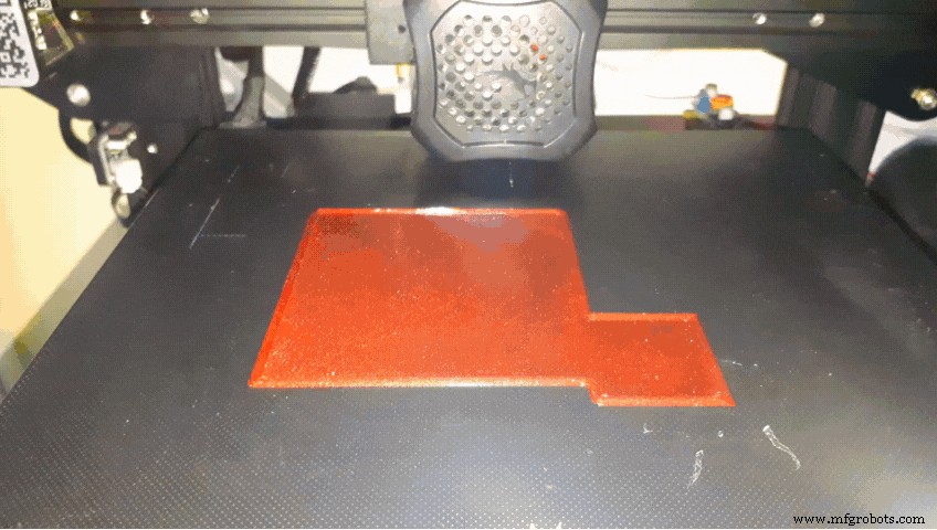

I designed all the parts in Fusion 360, sliced them in Cura and printed them with my Ender 3 V2 in PETG at 0.2mm layer height. You will need to print:
- The "Base.stl"
- The "RotatorDispenser.stl"
- The "CoverBase.stl"
- The "LaserClamp.stl"
- And the "LdrClamp.stl"
You can find all the files Here
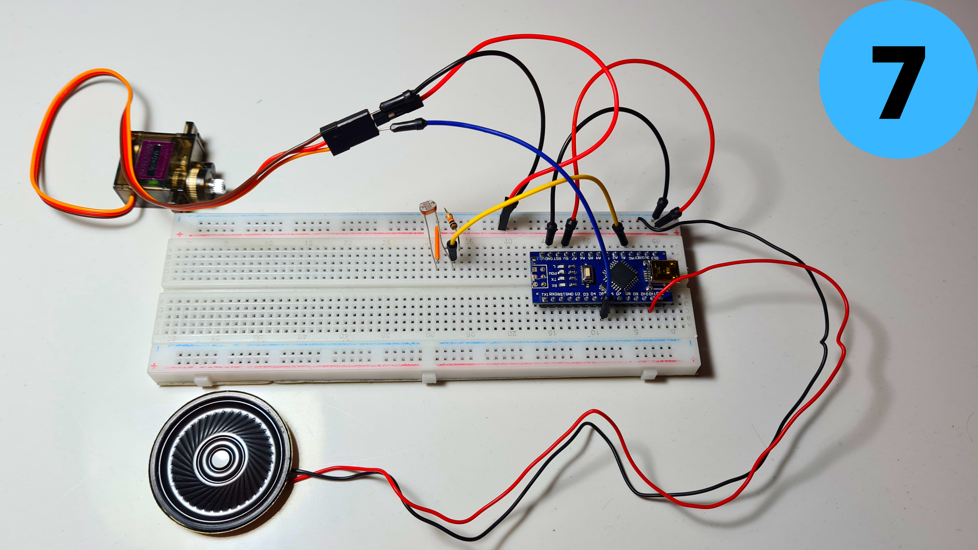
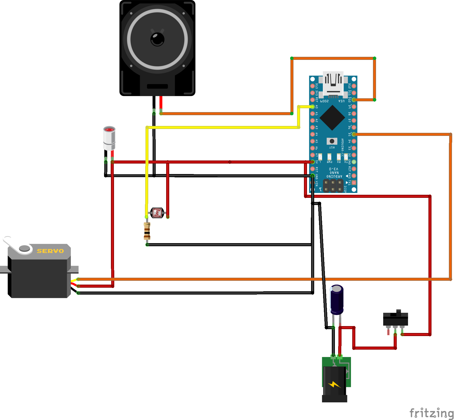
Step 3: Circuit Part 1
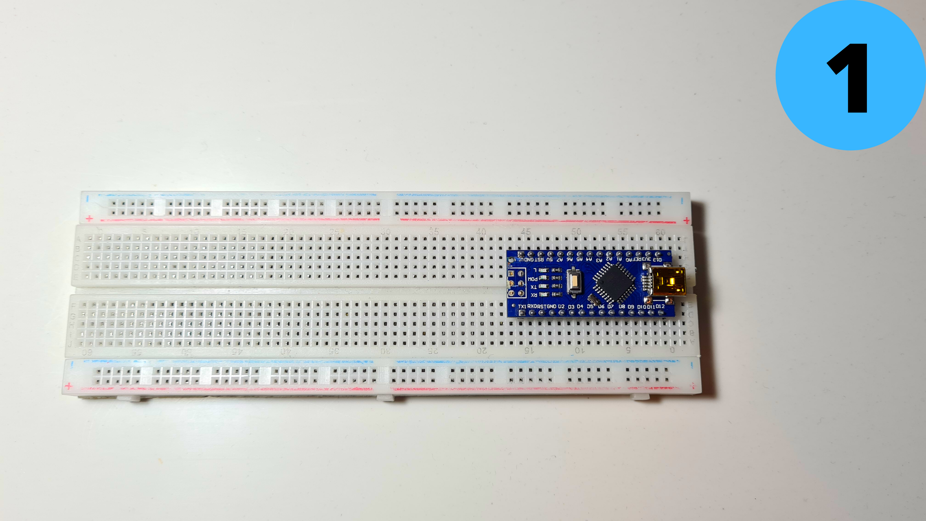
It's time to connect the electronics!!
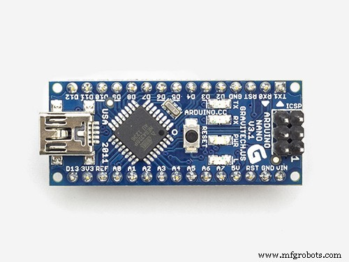
1. Place the Arduino Nano on the breadboard
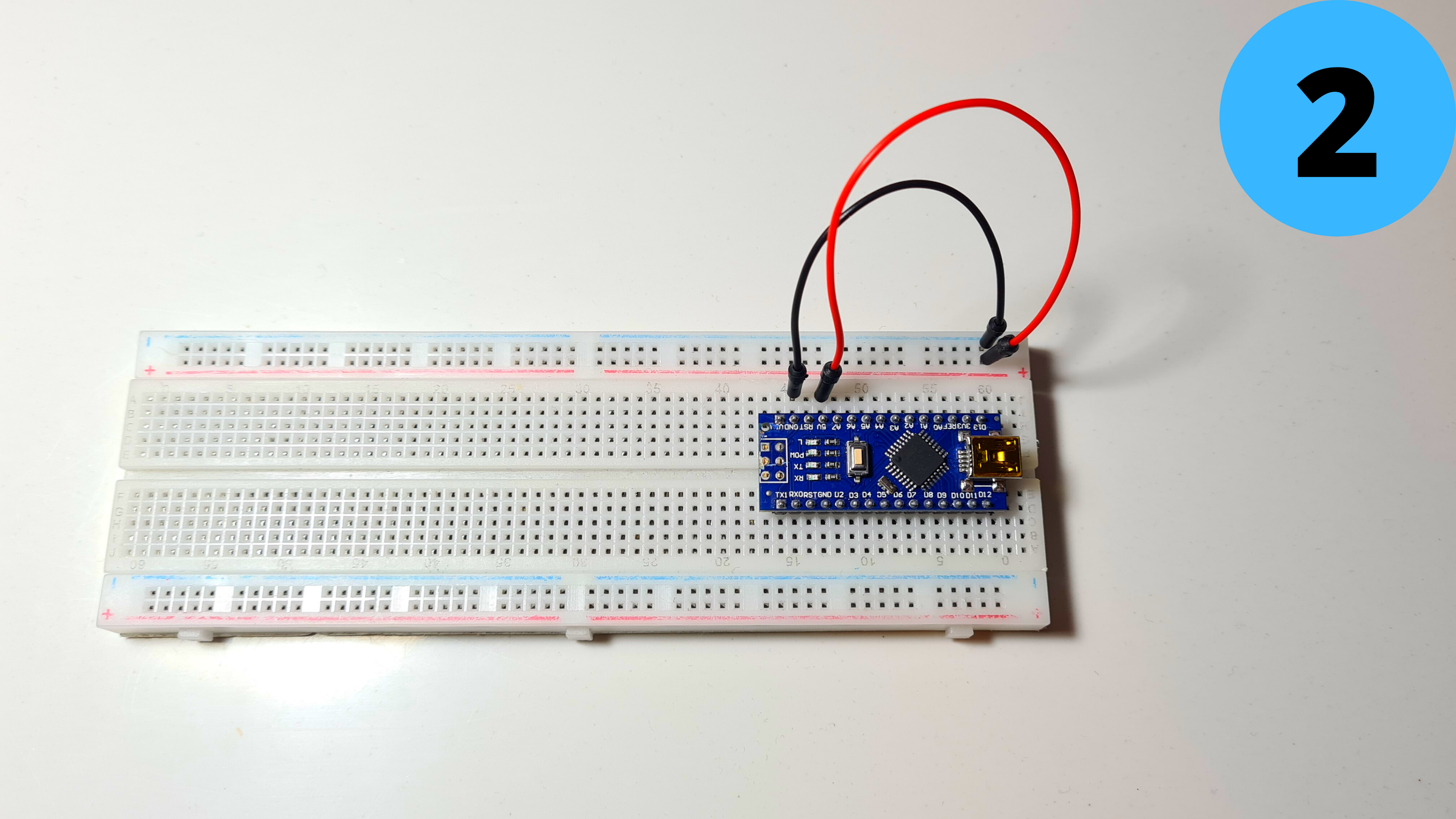
2. Connect 5V to Positive Rail (red) and GND to Negative Rail (blue)
Step 4: Circuit Part 2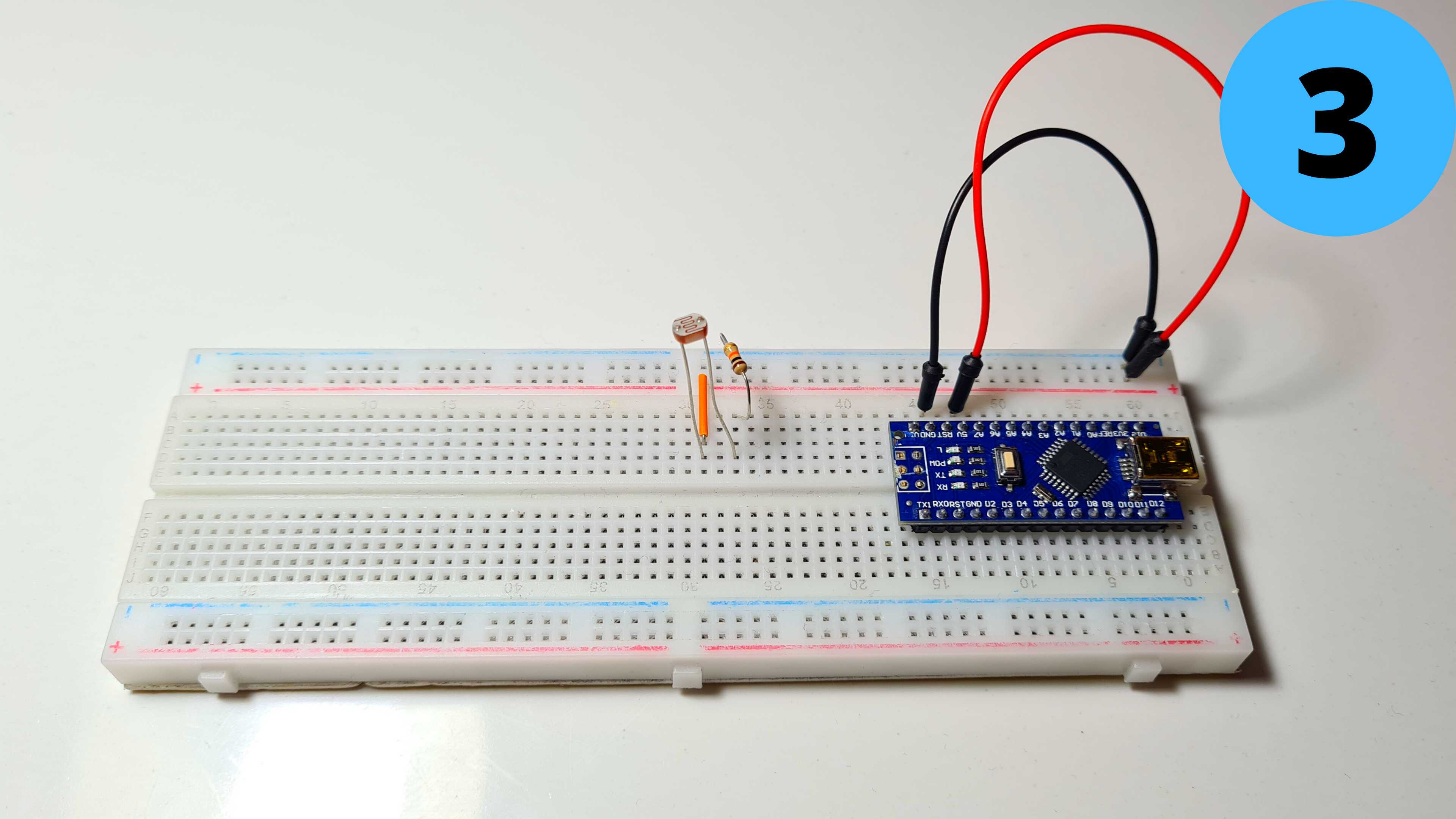
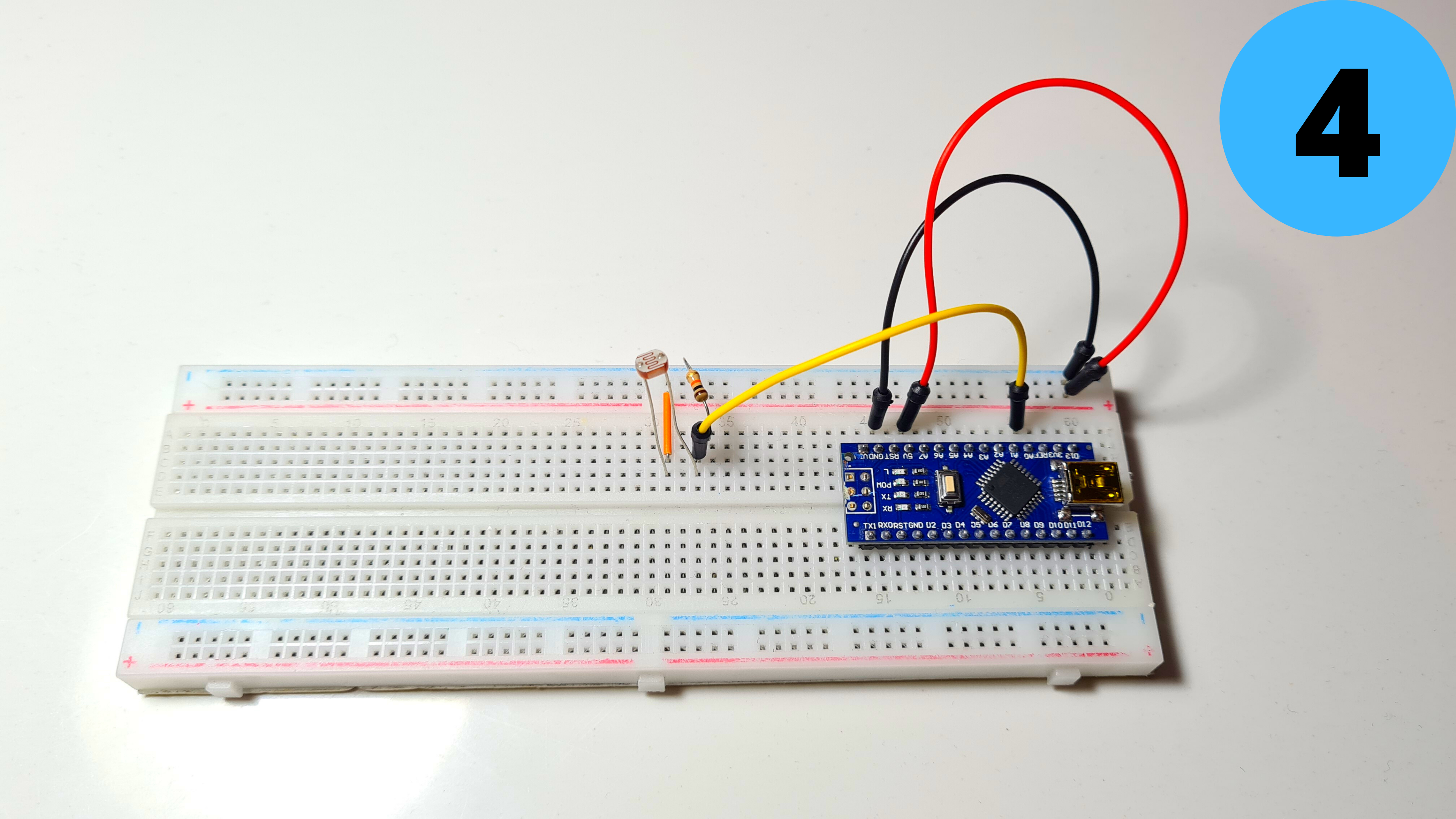
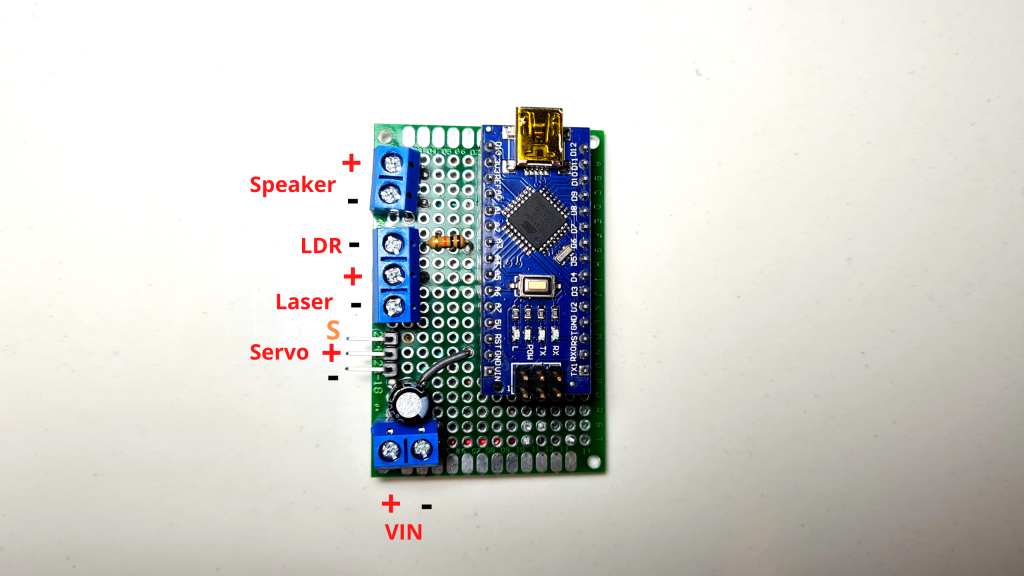
3. Add the LDR and connect one of its leads to 5V and the other one to GND with the 1kΩ resistor (the order doesn't matter)
4.Connect the second lead to A0 as well
5.Add the MG90S Servo and connect its Brown Wire to GND and its Red Wire to 5V
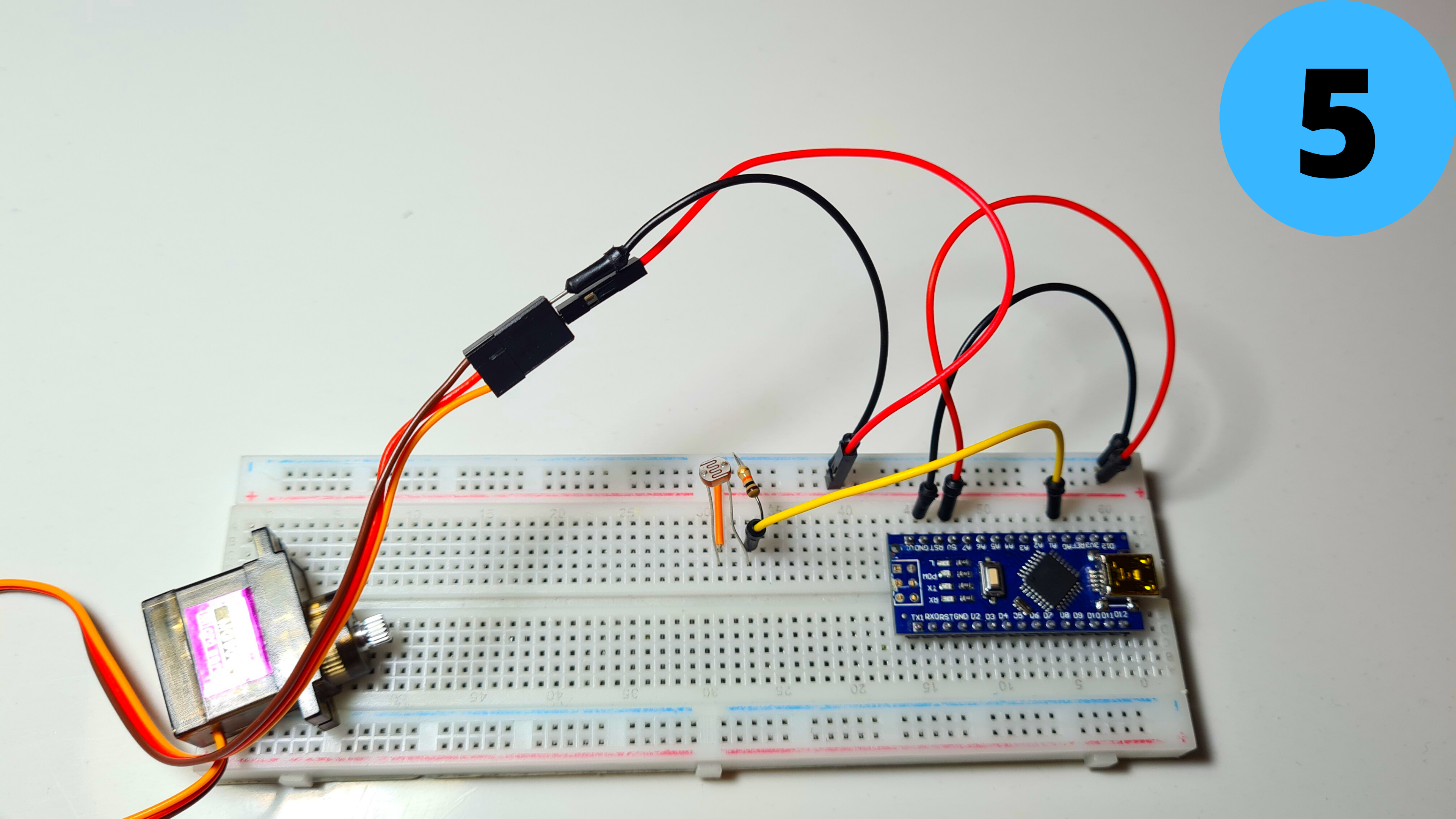
Step 5: Circuit Part 3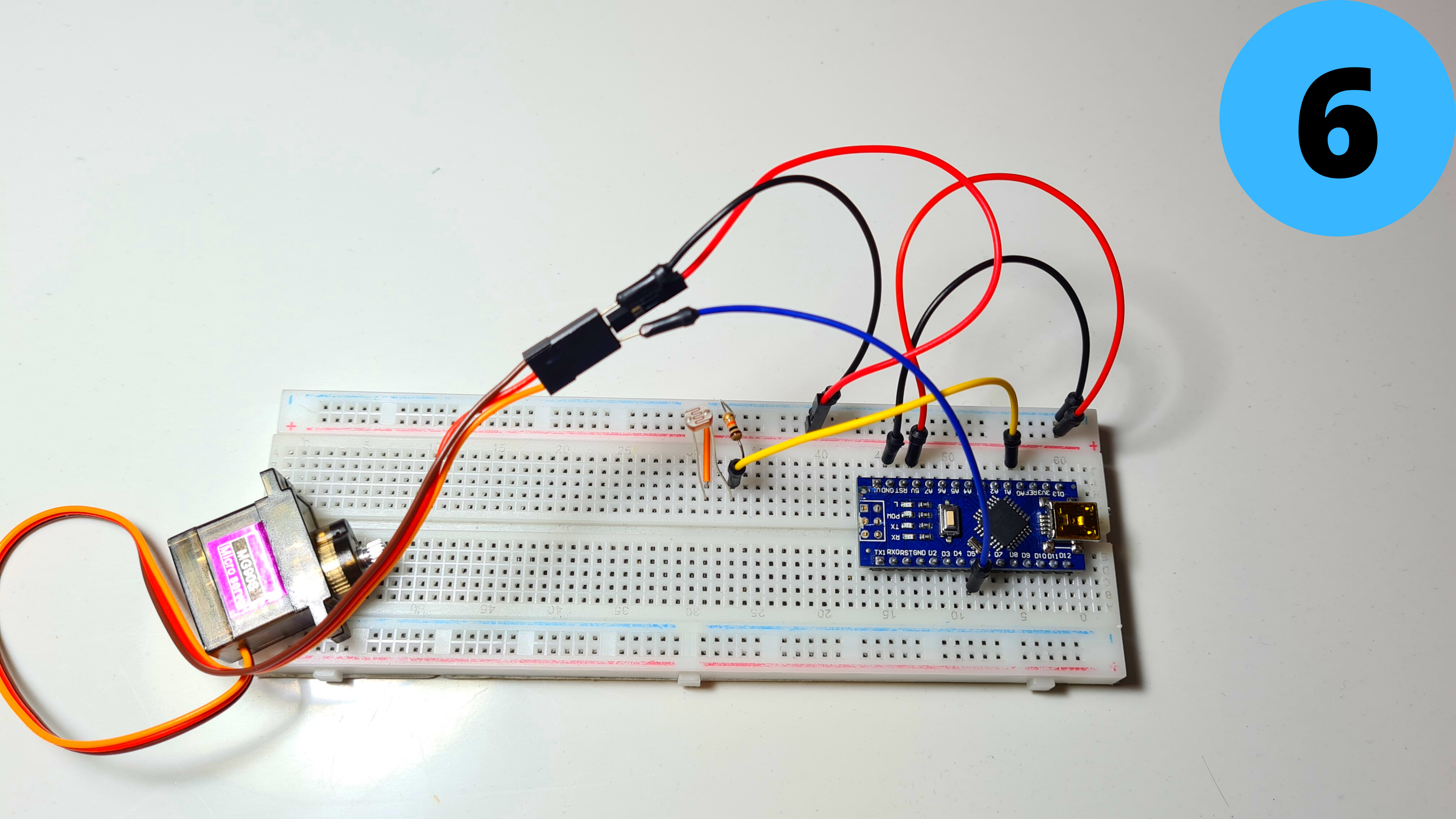
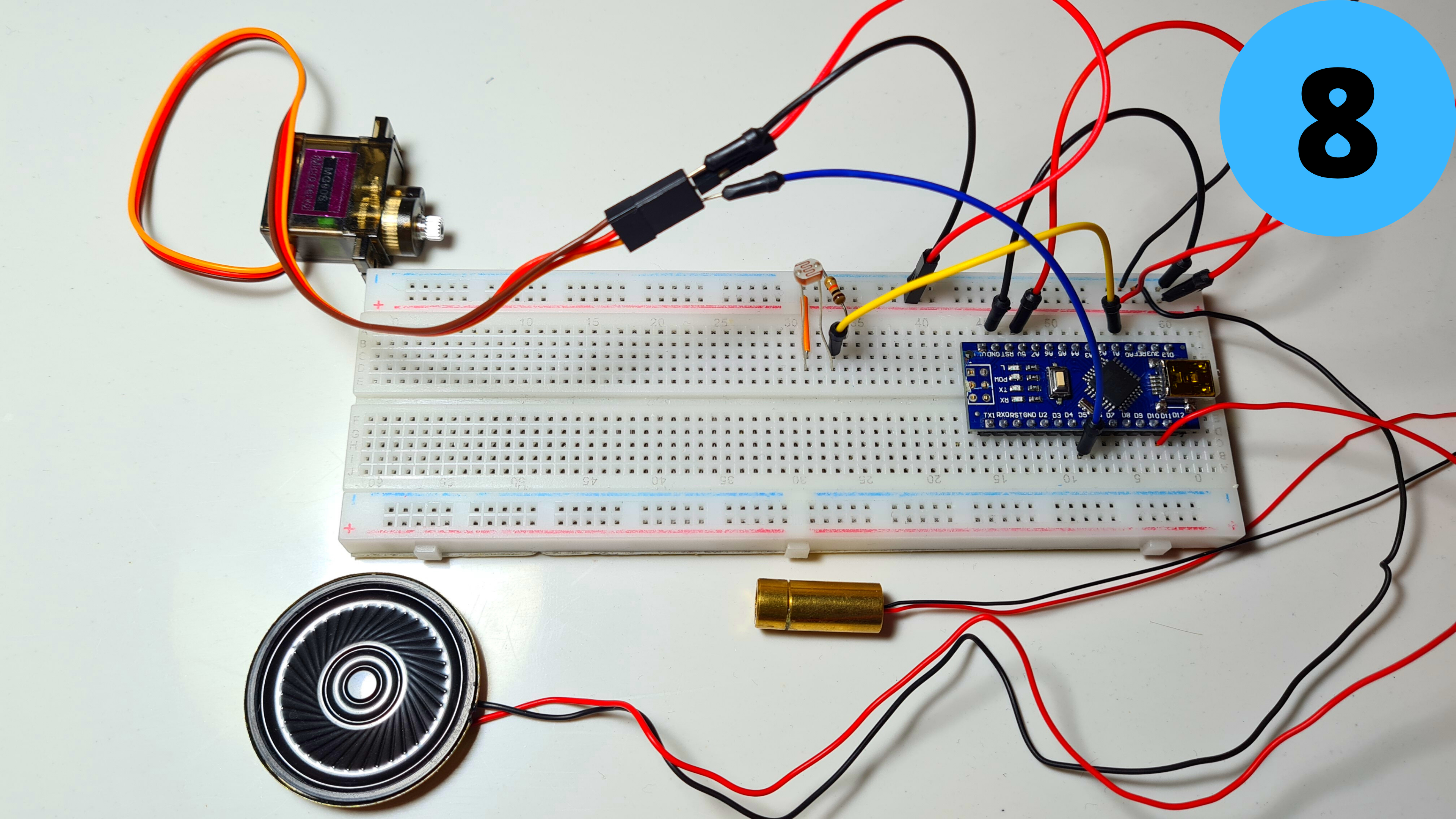
6. Connect the YellowWire to D5
7. Add the small speaker and connect its Red Wire (+) to D11 and its Black Wire (-) to GND
8. Finally add the Laser Module and connect its Red Wire (+) to 5V and its Black Wire (-) to GND
Step 6: Programming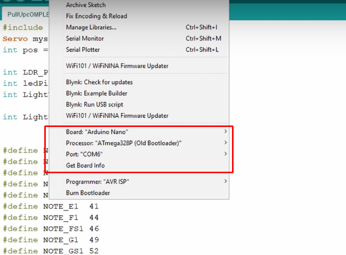
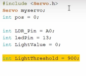
Time to program the Arduino Nano! I have attached my code below for you to download if you want. Open Arduino IDE select the Arduino Nano Board, your COM Port, click Upload and you're done! The LightThreshold defines how sensitive the LDR is to light, keep this in mind as I'll go into it deeper in the next step.
Take a look at adithyalokesh17's work as well! He has turned a lot of popular songs (Like "Take on me" which I used) into light Arduino code which is easy to use with buzzers and speakers without needing any complicated SD card readers etc.
Step 7: Test/Troubleshooting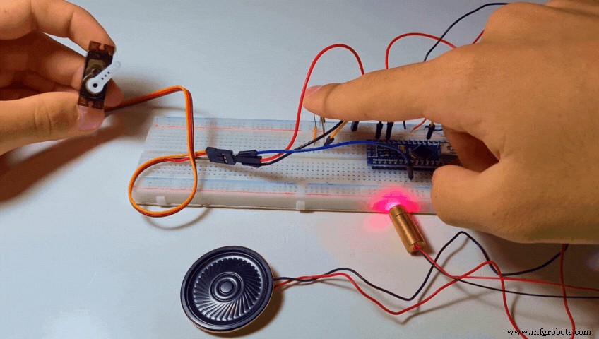
When the code gets uploaded nothing happens. Then I cover the LDR with my finger so that I block the light from reaching it. Pretty much a simulation of what will happen during the workout when my hands will block the laser beam. In both cases the If statement gets triggered, music starts playing and then the servo rotates and dispenses a Tic Tac.
There are two common problems that can ocure here even if you did everything properly.
- The music doesn't start playing when you cover the sensor. You can easily solve this by increasing the "LightThreshold" value we talked in the previous step thus making it more sensitive.
- The music starts playing without even covering the sensor. You can solve this be decreasing the "LightThreshold" value thus making it less sensitive.
Tips:
- A good tip to adjust the Threshold value just right would be to use the serial monitor and see the light values your sensor produces. (The can range anywhere between 0 (Absolute Darkness) to 1023 (Absolute Light)
- To get accurate measurements I would suggest aiming the laser diode to the LDR and working with those values instead of the ones of the ambient light of your room.
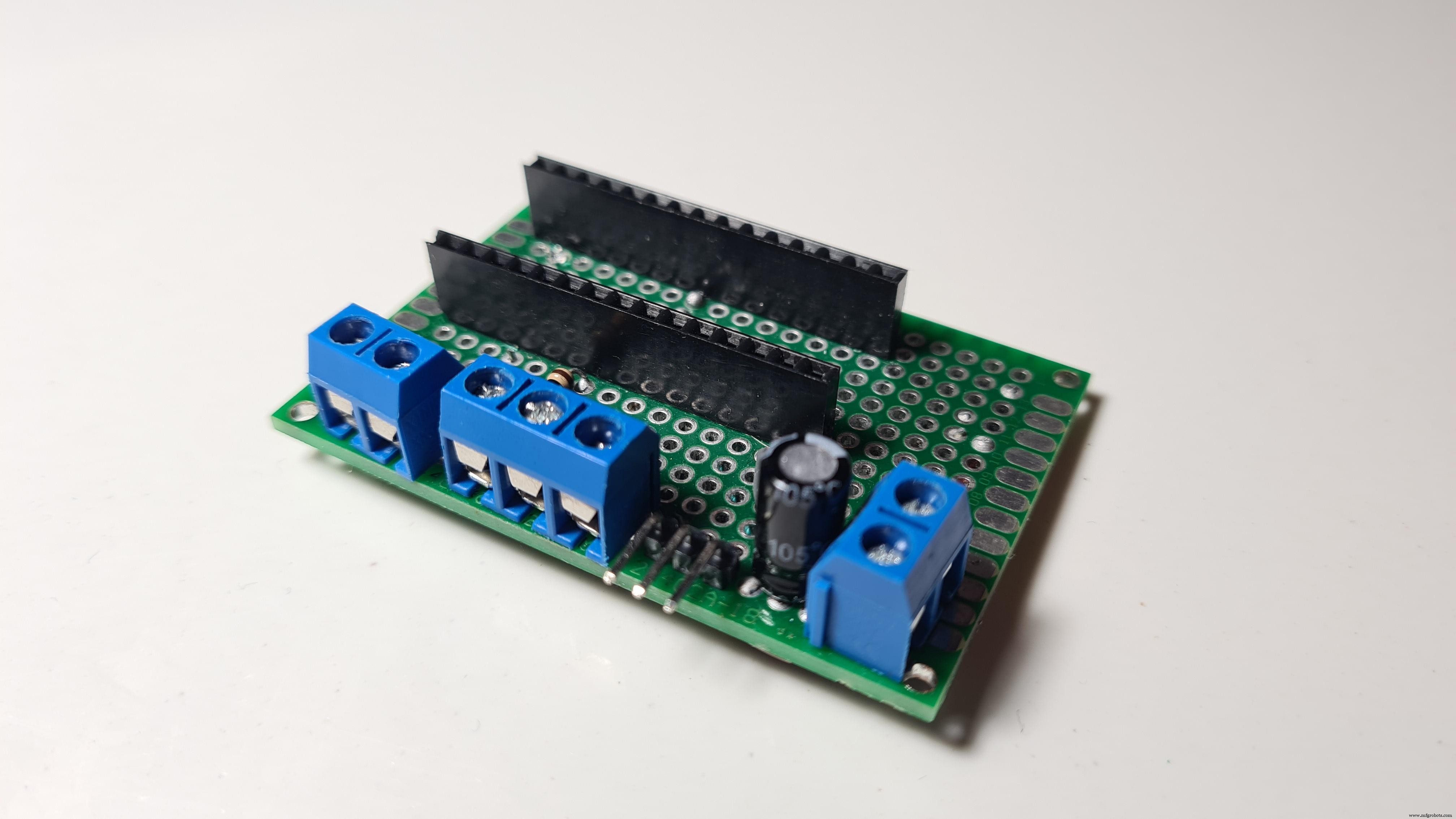
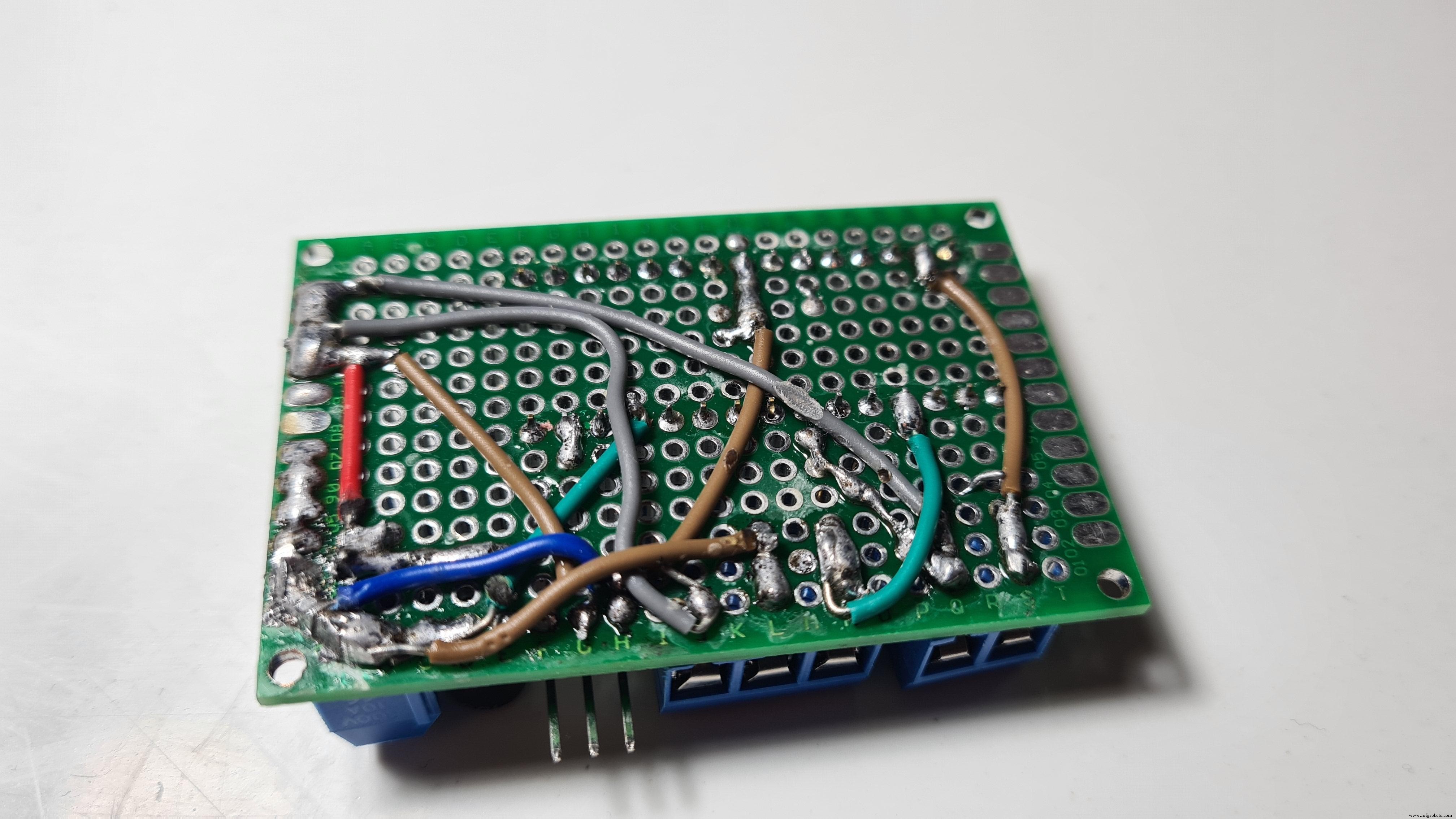

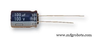
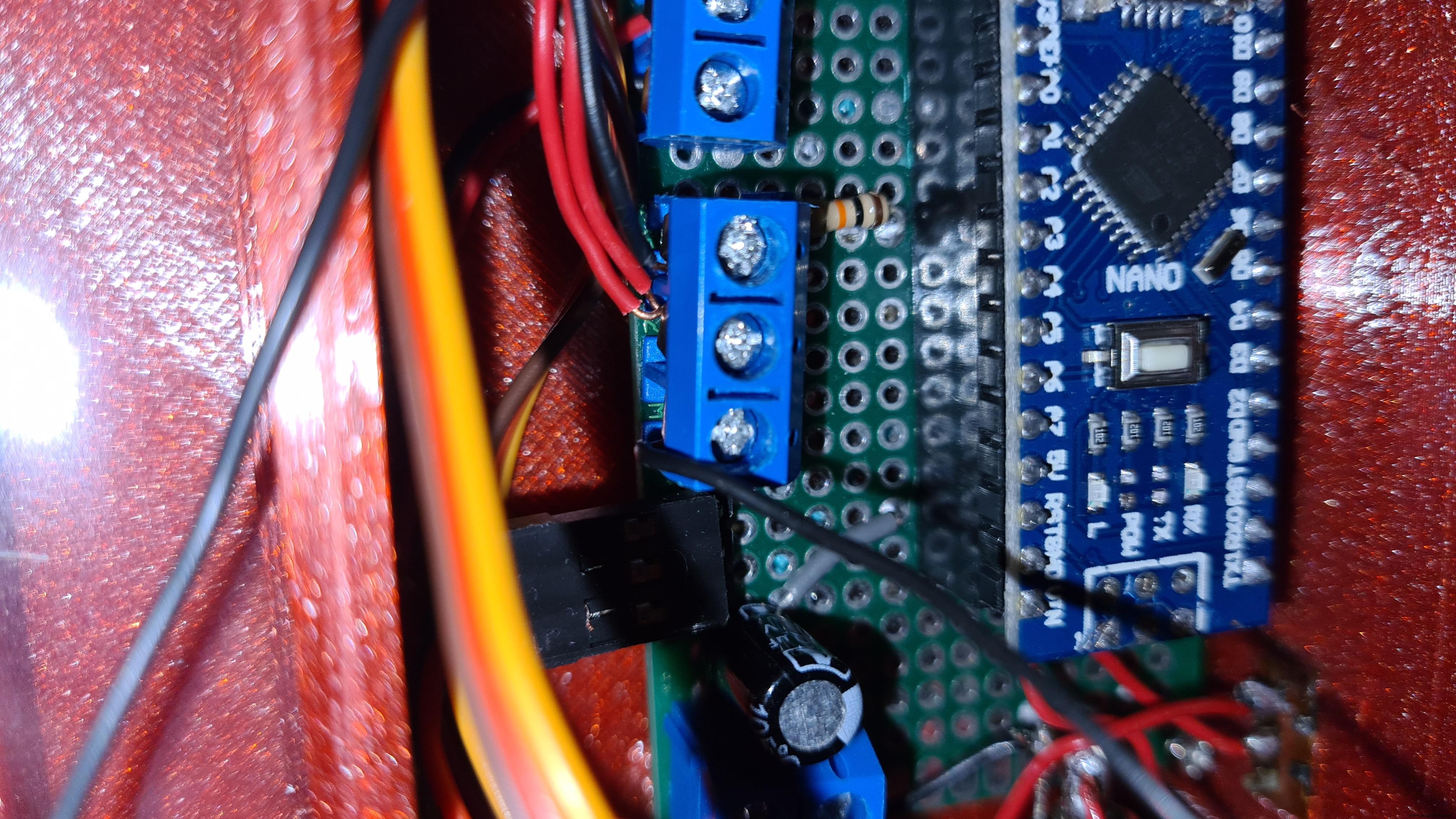
Since everything works it's time to make a pcb to fit all the components in a more compact enclosure. The only difference the PCB has from the breadboard circuit we made earlier is that I've included a Power Input terminal which connects (+) to 5V and (-) to GND and I have added a 100μF capacitor (optional) in parallel to smooth out the current.
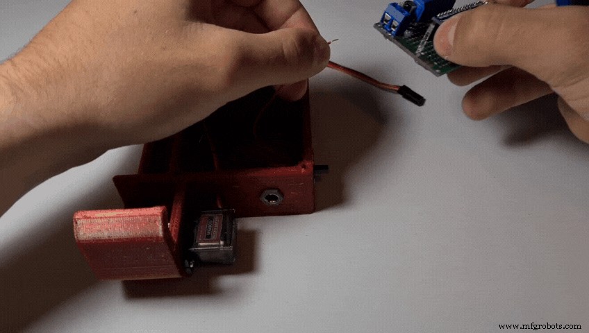
Step 9: Attaching the Servo
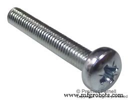
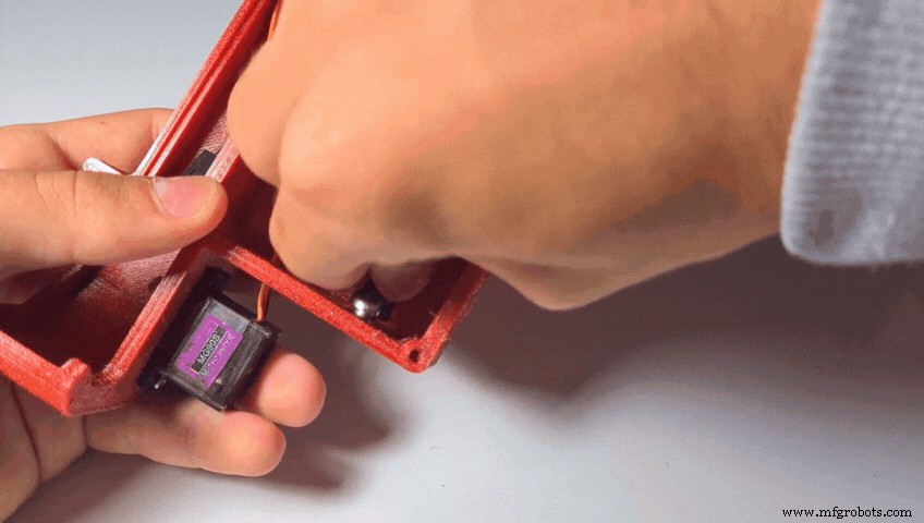
- Screw the servo to the Base using 1 or 2 M2 screws.
- Push the Laser Diode into the LaserClamp.
- Insert the LDR into the LdrClamp. (There are two small holes To pass the wires through)
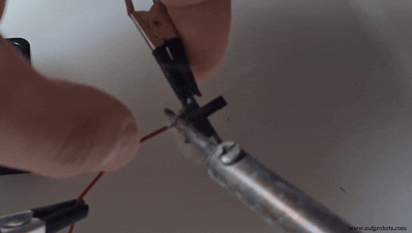
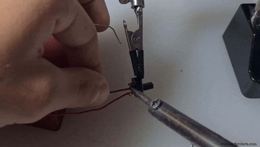
- Solder a preferably red wire to the positive lead of the DC Jack.
- Solder a black wire to the negative lead of the DC Jack.
- Solder a new red wire to the slide switch.
- Insert the DC Jack into its hole in the base. Secure it in place using the nut.
- Solder the red wire of the DC Jack to the other lead of the switch.
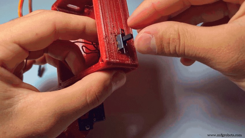
- Push the switch into place.

- Connect the red wire to the positive power input of the pcb.
- And the black wire to the negative power input.
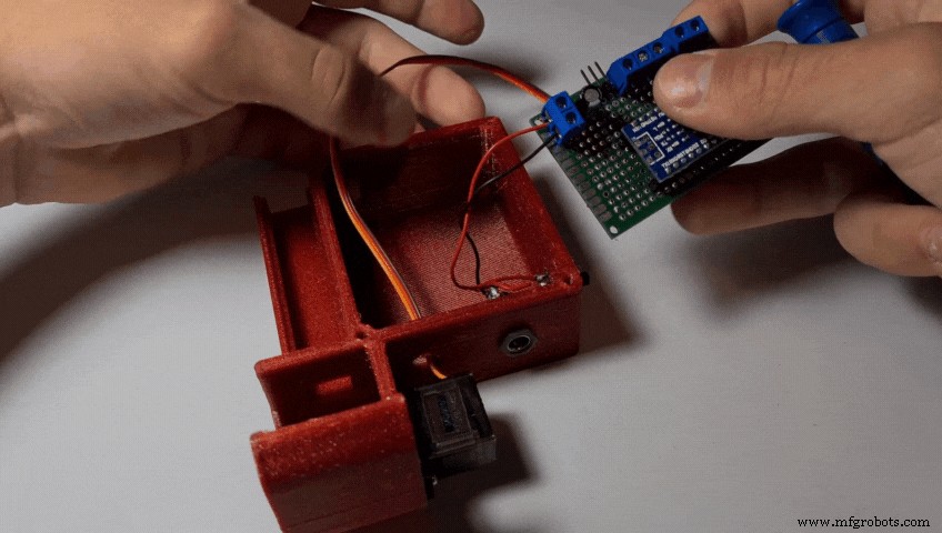
- Connect the servo to the male headers.
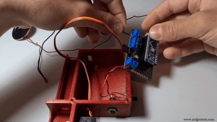
- Connect the speaker
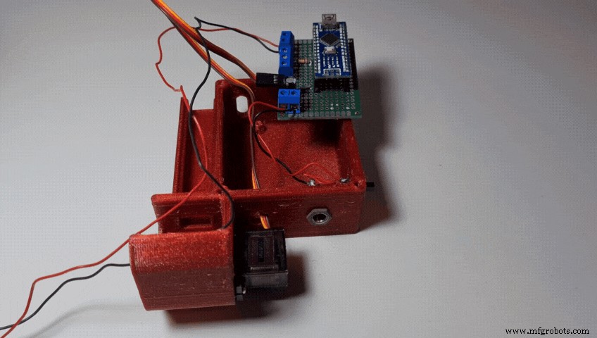
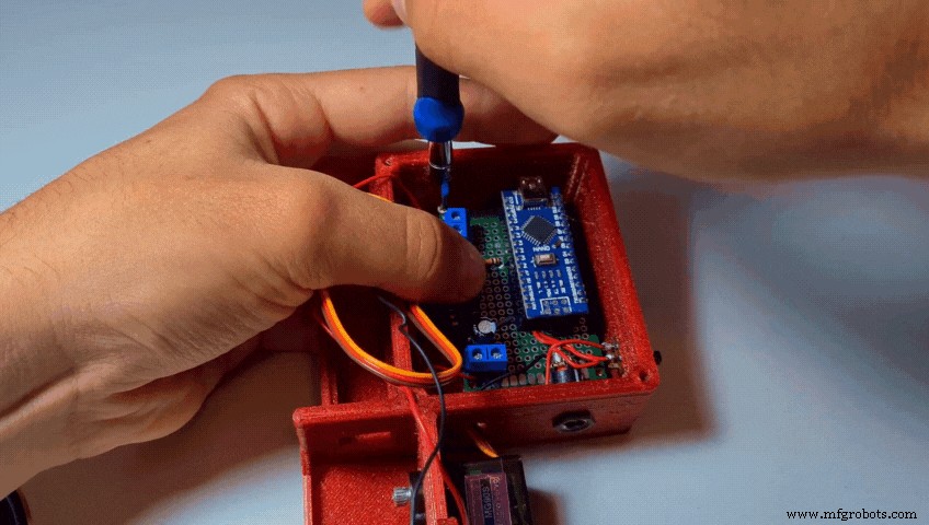
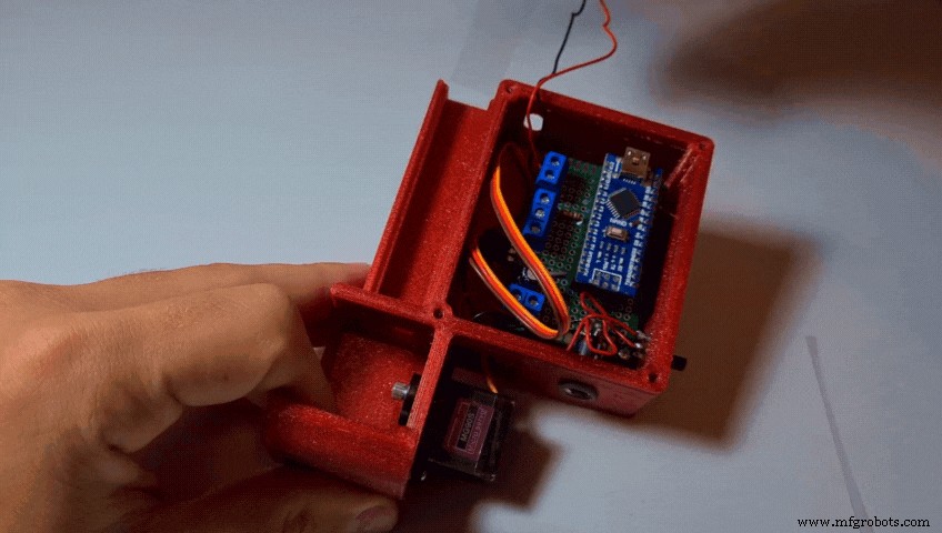
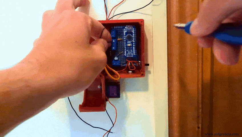
- Fit the PCB into the Base
- Secure it in place with 2-4 M2 screws
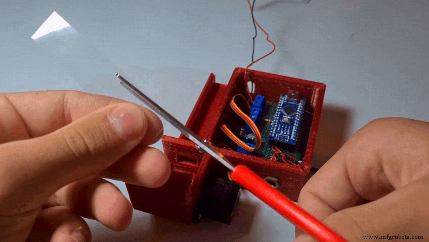
- Cut the transparent plastic sheet into a rectangle of around 75mm x 17mm and trim its sides until it fits tightly into the base.
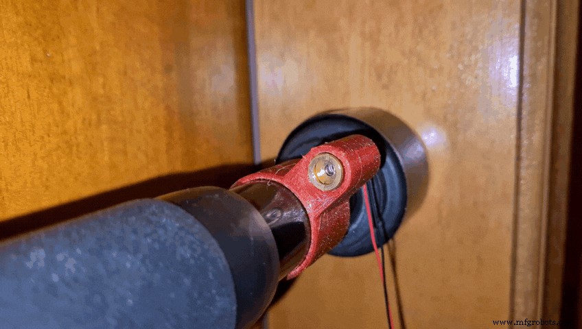
- Attach the LaserClamp to one side of the Pull-Up Bar and tighten the clamp using an M4 screw and nut
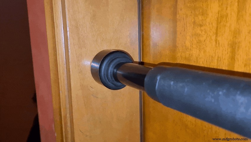
- Attach the LdrClamp to the other side of the Bar and tighten it again using an M4 screw and nut
- Turn on the Laser Module by connecting it to a ~5V power source (Arduino 5V pin, 3 x AA batteries, 1S Lipo, 18650 battery or whatever you prefer)
- Rotate the Clamps until the Laser Beam hits the center of the LDR
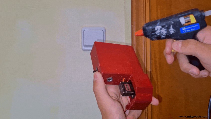
- Take the Hot Glue Gun, possibly all of the makers' most favorite tool, and glue the Base to your wall.
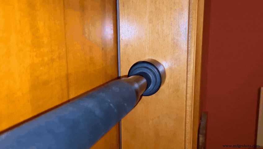
- Wrap the cables of the Laser and the LDR around your door
- Connect the two red wires to the central section of the triple screw terminal
- Connect the black wire of the LDR to the upper section
- And the black wire of the Laser to the other section
(Of course all these connections will differ based on how and if you make the PCB and mine can just be used as a concept refernce)
Step 26: Installing the Dispenser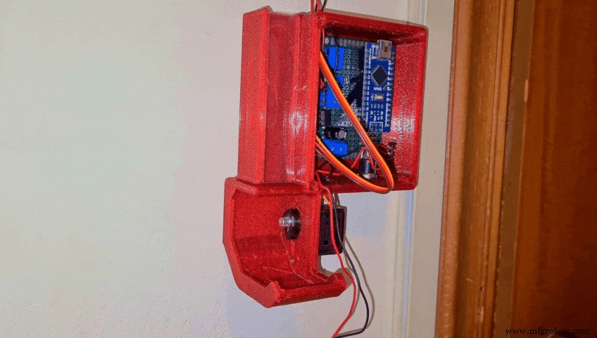
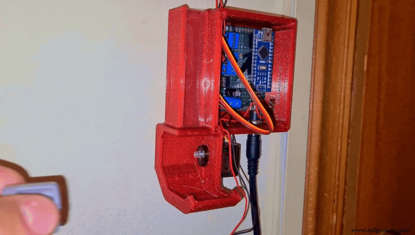
- Connect the Power Supply to the DC Jack and turn the switch on
When the Arduino first gets powered on, the servo automatically goes to its 0 degree position and locks in place. When that happens, attach the RotatorDispenser to it. Make sure that the two holes for the Tic Tacs align properly.
Step 27: Adding Cover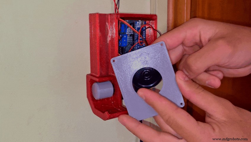
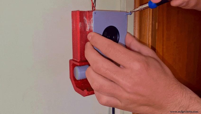
- Fit the speaker into the Cover
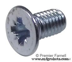
- Screw the cover to the Base using 2 - 4 x M3 screws
Lastly add some Tic Tacs…
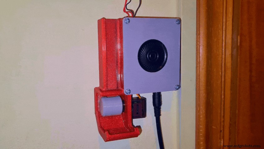
Step 29: Congratulations the Project Is Now Complete!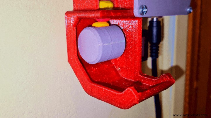
And the Smart Pull-Up Bar is finally complete!!
I hope you enjoyed this tutorial as much as I did making it! If you have any questions or suggestions let me know! Also consider subscribing to my YouTube Channel for more tutorials, cool builds and to support me throughout this journey. Have a great day!
Code
- SmartPullUpBar.ino
SmartPullUpBar.inoArduino
No preview (download only).
Custom parts and enclosures
Thingiverse
https://www.thingiverse.com/thing:4809522CAD file on thingiverse.comSchematics
Manufacturing process
- Bar Code Scanner: Technology, Design, and Future Trends
- Smart Bartender: Build Your Own Raspberry Pi‑Powered Cocktail Station
- Smart Traffic Light: Adaptive Street Lighting Powered by IoT
- Intelligent Smart Waste Bin: Optimising Waste Collection with IoT Sensors
- Smart Blinds: Automated Light Control with Arduino & Solar Power
- Smart Plug: 120V Arduino‑Based Smart Outlet with Real‑Time Clock
- Smart Pill Dispenser: Precision Medication Management System
- Enhancing Workplace Ergonomics with Intelligent Electric Actuators
- Alloy 52 Bar: High-Performance Nickel-Iron Steel with Superior Strength
- Boring Bar Diameter‑to‑Length Ratio Guidelines for CNC Machinists