


DIY Hot Glue LED Matrix Lamp – Build Your Own Colorful Display
Components and supplies
 |
| × | 128 | |||
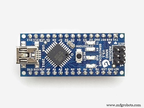 |
| × | 1 | |||
| × | 1 | ||||
 |
| × | 1 | |||
 |
| × | 1 | |||
 |
| × | 1 | |||
| × | 1 | ||||
| × | 1 | ||||
| × | 1 | ||||
| × | 1 | ||||
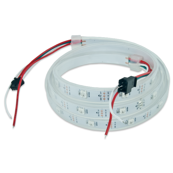
| × | 64 |
Necessary tools and machines
 |
|
Apps and online services
 |
|
About this project
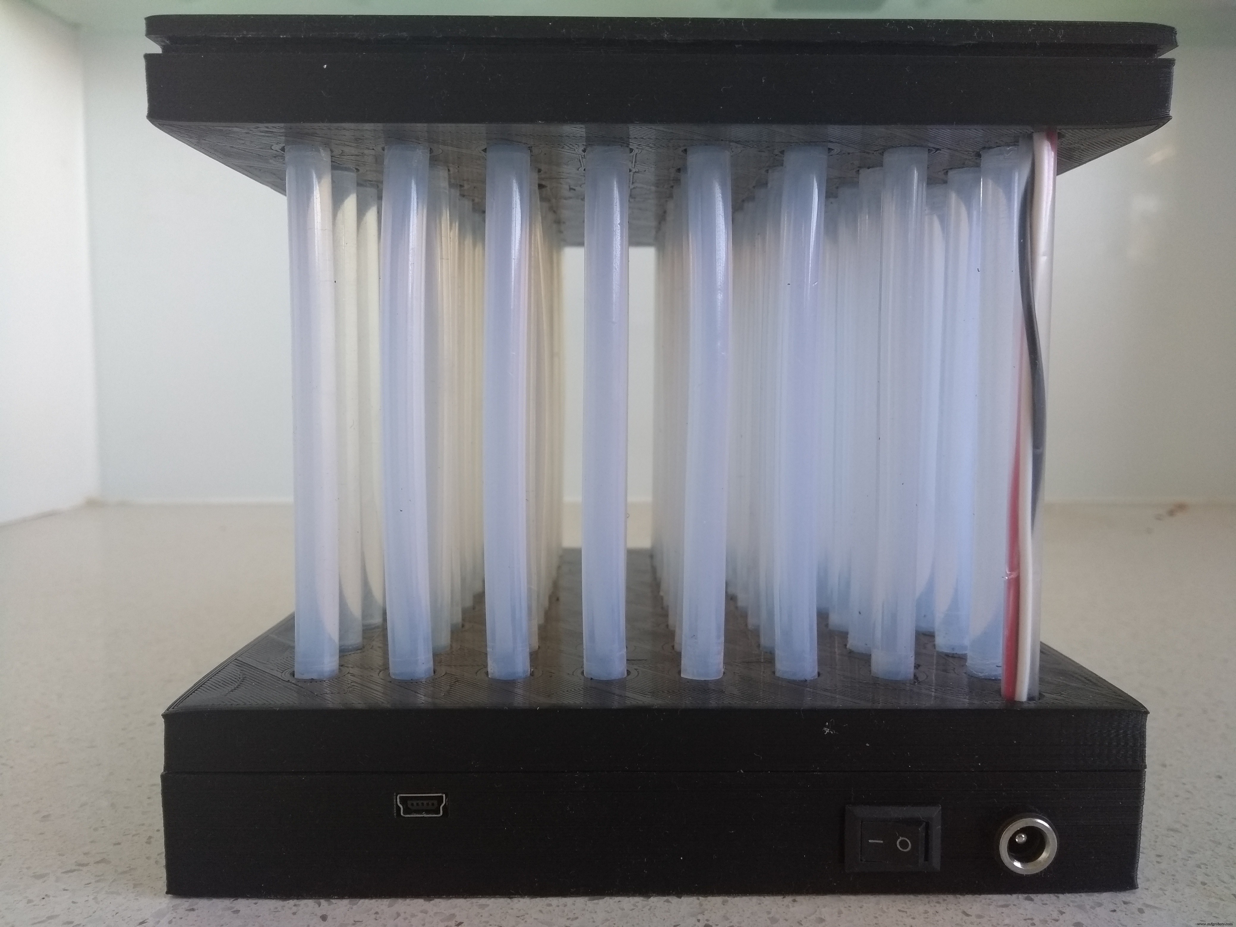
This lamp was based on a similar lamp called "Fiber Optic" LED Matrix by jbumstead. Using OpenSCAD, the goal was to replace the 12mm Diffused Digital RGB LED used in jbumstead's design with cheap WS2812B RGB strips and to make the container for the LEDs and electronics as thin as possible allowing cheaper 7mm glue sticks to be used.
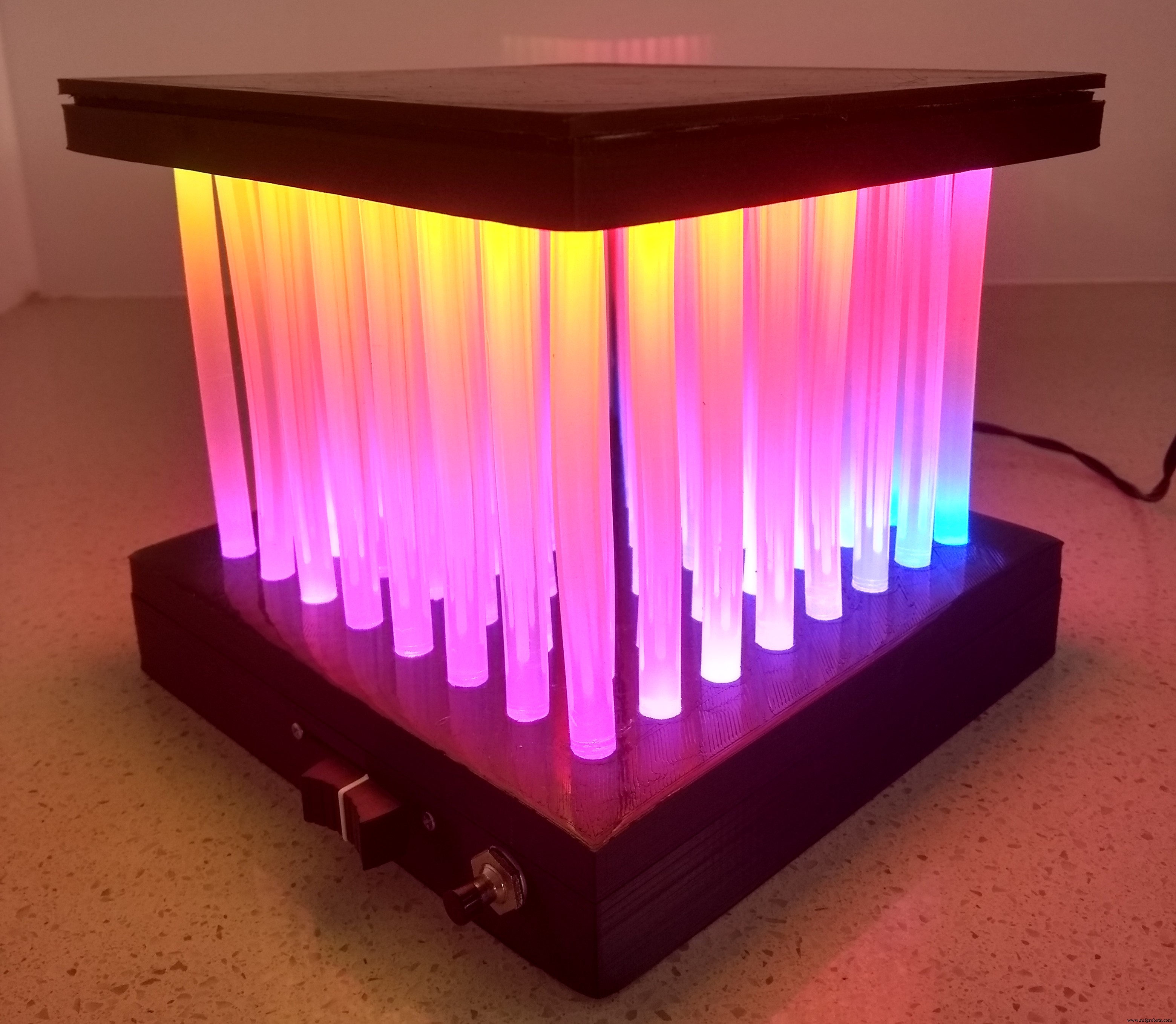
The only part that requires supports is "Hot Glue Matrix - Bottom.stl". I used a 0.2mm layer height and a 15% infill. I found that by increasing the hole size using a 19/64" drill after printing made it easier to insert the glue sticks into their respective holes.
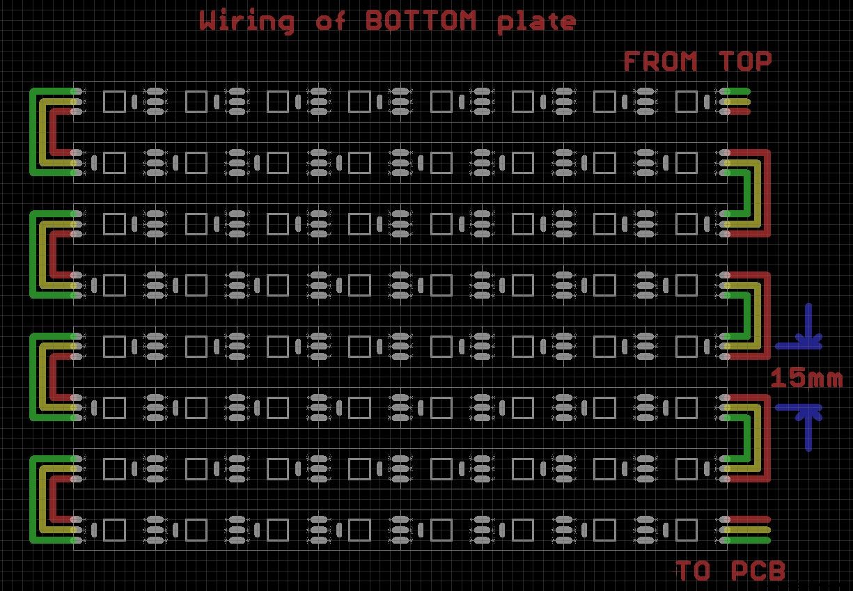
Assembling the Lamp Section1. Cut the WS2812B LED strips into 16 strips each containing 8 LEDs.
2. You cannot wire the LED strips together directly on the top or bottom forms as they are placed on each form upside-down. Stick 8 strips onto a flat surface with the center of each strip 15mm from its adjacent strip. Arrange the strips so that every alternative strip faces the opposite direction.
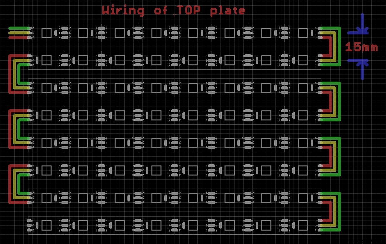
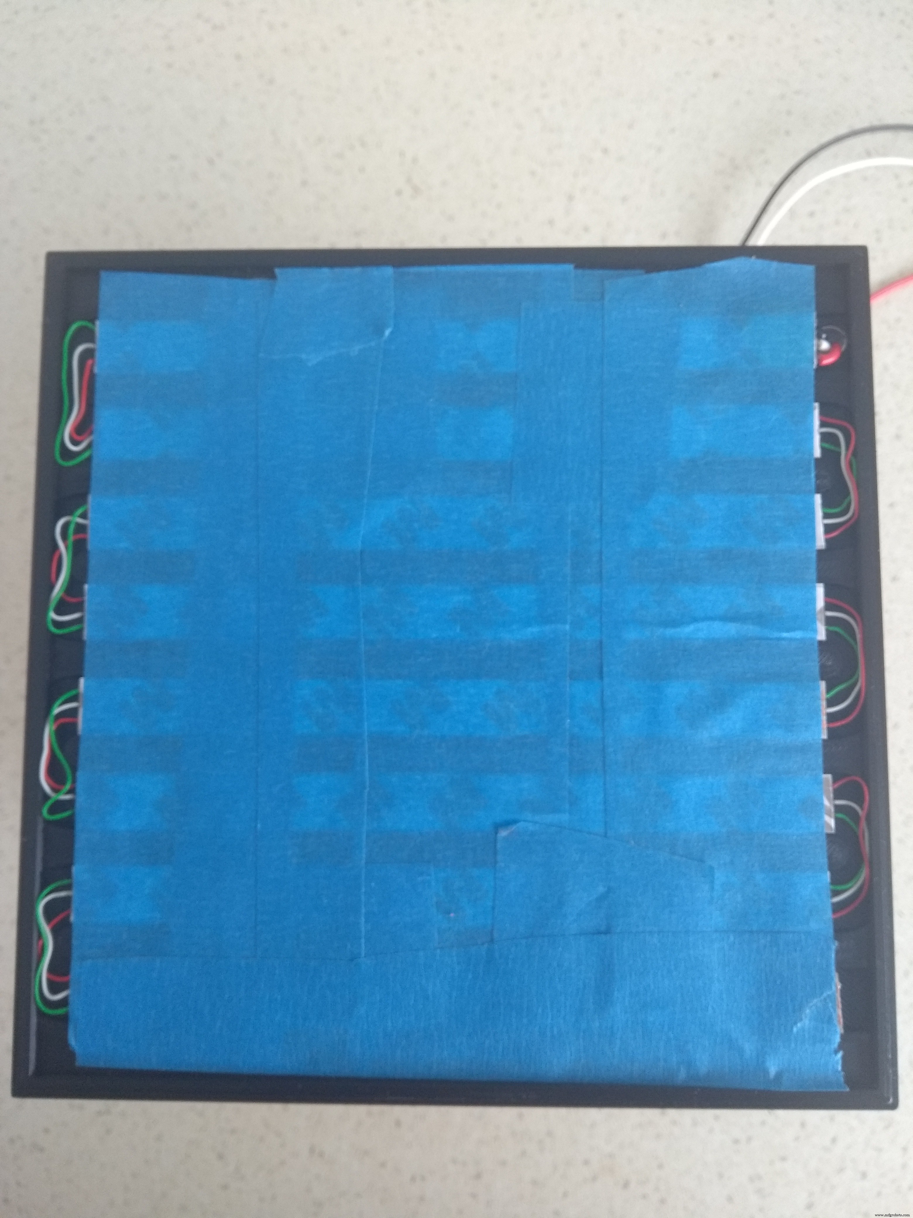
Ensure DIN is in the top-left corner. Wire the strips as shown above. I used wire-wrap wire but you can use any thin insulated copper wire. Once it is wired, add three long multi-strand wires to GND, DIN and +5V. These wires will go through a hole and join up with GND, DOUT and +5V of the bottom section. Now feed the three wires through the hole on the "Hot Glue Matrix - Holder Top" form and carefully place the strips upside down into their respective channels. The strips should sit flat. If not check the strips are the correct way round. They only go in one way. There are channels for the wires as well. Once the LED strips are in position, use Blue Painters Tape to secure them in place.
3. Wire up the bottom plate in a similar way. DOUT is top right. Add the three long multi-strand wires to VCC, DIN and GND before placing the strips upside-down onto the form. These wires will go to the PCB.
4. Don't connect the wires from the top section yet until all the glue sticks are in place.
Adding the Glue SticksThis will require some patience. Firstly you need to sort out the glue sticks. The 7mm glue sticks that you get from eBay are around 100m long. I found that they varied a bit. Mine came in packs of 30 so I had 90 sticks to find 64 of similar length. Also I needed to increase the hole size using a 19/64" drill after printing to make them easier to fit in the holes.
I also used a clear drinking straw to place the three wires that connect the top and bottom strips together into.
Add the glue sticks one row at a time starting at one end and working your way to the other end. Once they are all in place, measure the distance between the top and bottom at each corner. They should all be EXACTLY the same. If not, adjust the depth of the glue sticks accordingly. Once you are happy with the alignment, remove the glue sticks from each corner and put them back in-place with a small amount of super glue. (Don't get super glue on the LED). This should make the structure quite robust.
Carefully lift the bottom strip near the hole, trim the three wires and solder them in-place. +5V to +5V, DIN (top) to DOUT (bottom), GND to GND.
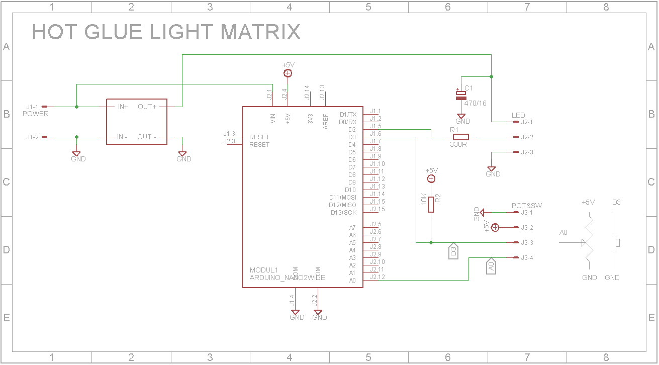
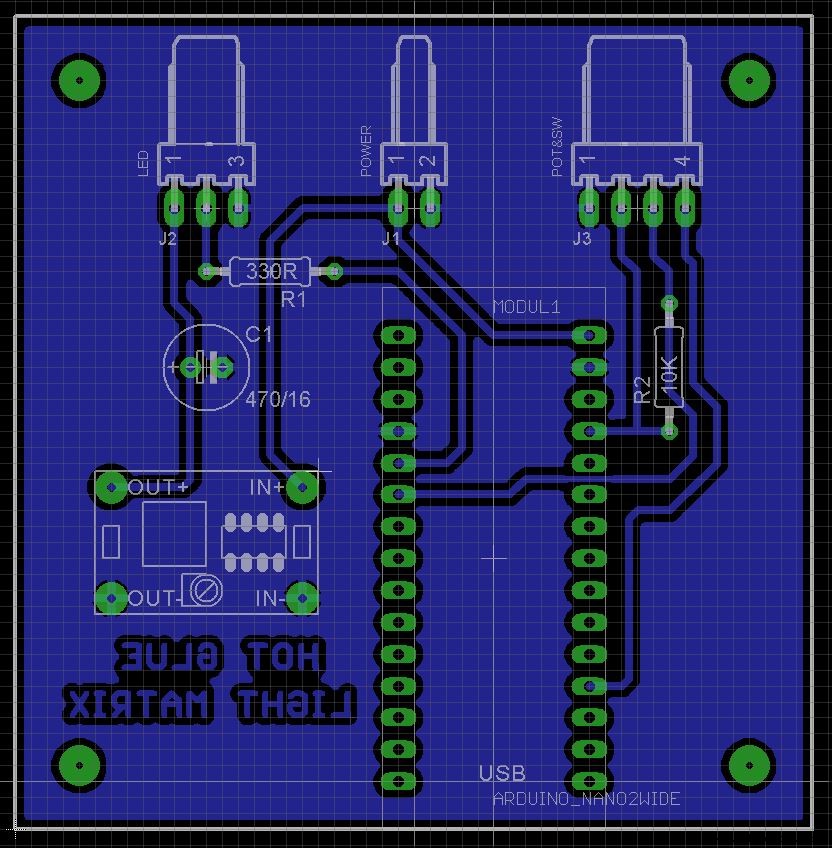
Making the PCBI have included the Eagle files if you wish to get the board commercially made or do as I did and make it yourself. I made my board using the toner method. You can just use a piece of proto board if you wish as the schematic is very simplistic and easy to wire up. The 4 mount holes should be drilled out with a 2.5mm drill and a thread created with a 3mm tap. Use 6mm M3 screws to hold the board in place.
IMPORTANT: Set the output of the DC regulator to 5V BEFORE fixing it to the board.
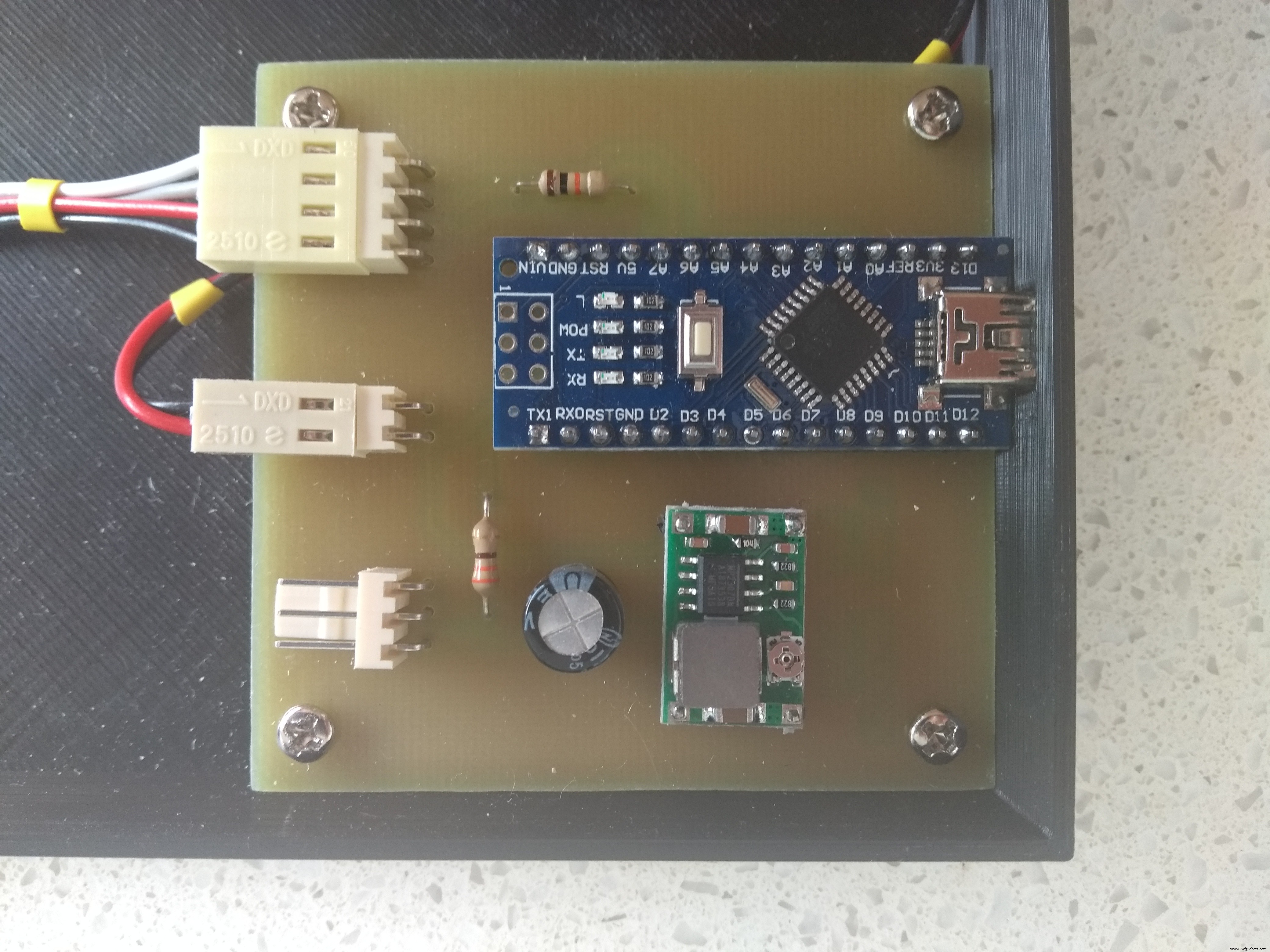
Wire up the slide potentiometer, push switch, power switch and DC power socket as shown below:
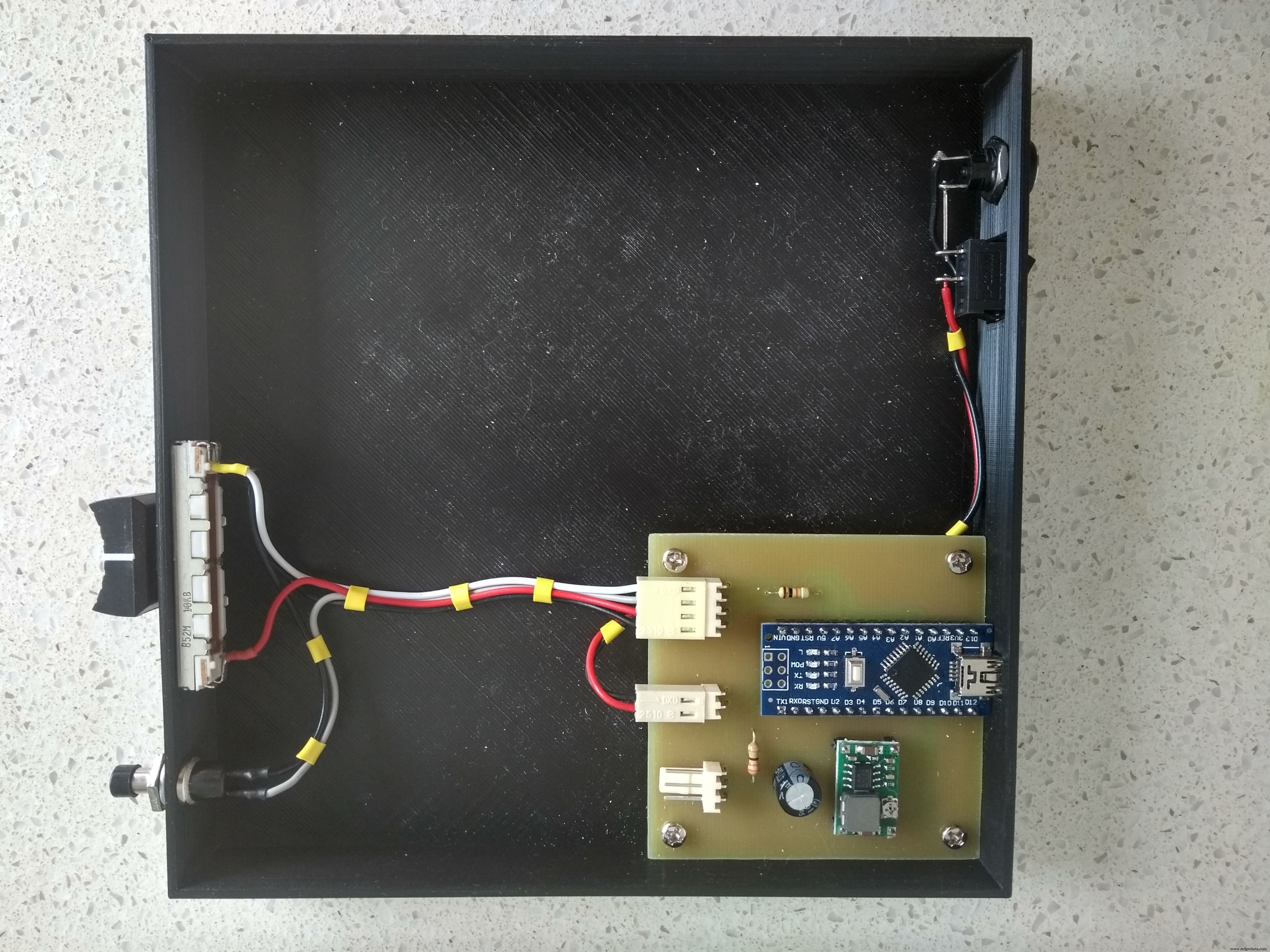
Connect the wires from the LED strips to the PCB.
SoftwareThe software included runs a series of test animations. The button cycles through the available animations. The potentiometer adjusts the speed of the animations.
Code
- GlueMatrixTest.ino
- Button.h
- Button.cpp
GlueMatrixTest.inoC/C++
#include <Adafruit_NeoPixel.h>
#ifdef __AVR__
  #include <avr/power.h>
#endif

#include "Button.h"

#define PIN_LED 2
#define PIN_SWITCH 3
#define PIN_POT A0

#define LEDS 128

// Parameter 1 = number of pixels in strip
// Parameter 2 = Arduino pin number (most are valid)
// Parameter 3 = pixel type flags, add together as needed:
//   NEO_KHZ800  800 KHz bitstream (most NeoPixel products w/WS2812 LEDs)
//   NEO_KHZ400  400 KHz (classic 'v1' (not v2) FLORA pixels, WS2811 drivers)
//   NEO_GRB     Pixels are wired for GRB bitstream (most NeoPixel products)
//   NEO_RGB     Pixels are wired for RGB bitstream (v1 FLORA pixels, not v2)
//   NEO_RGBW    Pixels are wired for RGBW bitstream (NeoPixel RGBW products)
Adafruit_NeoPixel strip = Adafruit_NeoPixel(LEDS, PIN_LED, NEO_GRB + NEO_KHZ800);
Button mode = Button(PIN_SWITCH);
bool modePressed = false;

//Physical LED map for bottom and top LED arrays

//LED Bottom (Back looking from top)
//064 049 048 033 032 017 016 001
//063 050 047 034 031 018 015 002
//062 051 046 035 030 019 014 003
//061 052 045 036 029 020 013 004
//060 053 044 037 028 021 012 005
//059 054 043 038 027 022 011 006
//058 055 042 039 026 023 010 007
//057 056 041 040 025 024 009 008
//(Front looking from top)

//LED Top (Back looking from top)
//065 080 081 096 097 112 113 128
//066 079 082 095 098 111 114 127
//067 078 083 094 099 110 115 126
//068 077 084 093 100 109 116 125
//069 076 085 092 101 108 117 124
//070 075 086 091 102 107 118 123
//071 074 087 090 103 106 119 122
//072 073 088 089 104 105 120 121
//(Front looking from top)

const uint8_t botLED[] PROGMEM = {
  64,49,48,33,32,17,16,1,
  63,50,47,34,31,18,15,2,
  62,51,46,35,30,19,14,3,
  61,52,45,36,29,20,13,4,
  60,53,44,37,28,21,12,5,
  59,54,43,38,27,22,11,6,
  58,55,42,39,26,23,10,7,
  57,56,41,40,25,24,9,8,
};

const uint8_t topLED[] PROGMEM = {
  65,80,81,96,97,112,113,128,
  66,79,82,95,98,111,114,127,
  67,78,83,94,99,110,115,126,
  68,77,84,93,100,109,116,125,
  69,76,85,92,101,108,117,124,
  70,75,86,91,102,107,118,123,
  71,74,87,90,103,106,119,122,
  72,73,88,89,104,105,120,121
};

//Storage for current values
int red = 128;
int green = 128;
int blue = 128;
int pattern = 1;

// IMPORTANT: To reduce NeoPixel burnout risk, add 1000 uF capacitor across
// pixel power leads, add 300 - 500 Ohm resistor on first pixel's data input
// and minimize distance between Arduino and first pixel.  Avoid connecting
// on a live circuit...if you must, connect GND first.

void setup()
{
  Serial.begin(115200);

  pinMode(PIN_LED, OUTPUT);
  pinMode(PIN_SWITCH, INPUT);
  pinMode(PIN_POT, INPUT);

  //Pixel Strip
  Serial.println("Setup()");
  strip.begin();
  strip.show(); // Initialize all pixels to 'off'

  //Button callbacks
  //mode.Background(ButtonBackground);

  //Set ISR for pin change on MODE pin
  Button::PinChangeSetup(PIN_SWITCH);
}

void loop()
{
  if (modePressed)
  {
    pattern = (pattern % 8) + 1;
    strip.clear();
  }
  modePressed = false;
  Serial.print("Mode ");
  Serial.print(pattern, DEC);
  Serial.println();
	switch (pattern)
	{
	  case 1: colorWipe(strip.Color(255, 0, 0)); break; // Red
	  case 2: colorWipe(strip.Color(0, 255, 0)); break; // Green
	  case 3: colorWipe(strip.Color(0, 0, 255)); break; // Blue
	  case 4: theaterChase(strip.Color(127, 127, 127)); break; // White
	  case 5: rainbow(); break;
    case 6: rainbowDifference(); break;
	  case 7: rainbowCycle(); break;
    case 8: rainbowCycleDifference(); break;
	  case 9: theaterChaseRainbow(); break;
	}
	if (!modePressed)
	{
    modePressed = mode.Pressed();
	}
}

//Mode button interrupt to break out of loops etc
//PCINT1 handles pin changes for pins for A0 to A5
ISR (PCINT2_vect)
{
  modePressed = modePressed | (mode.State() == LOW);
}

void ButtonBackground(void)
{
}

// Fill the dots one after the other with a color
void colorWipe(uint32_t c)
{
  int total = strip.numPixels() / 2;
  for(uint16_t i=0; i < total && !modePressed; i++)
  {
    uint8_t botIndex = pgm_read_byte(&botLED[i]) - 1;
    strip.setPixelColor(botIndex, c);
    uint8_t topIndex = pgm_read_byte(&topLED[i]) - 1;
    strip.setPixelColor(topIndex, c);
    strip.show();
    delay(map(analogRead(PIN_POT), 0, 1024, 100, 0));
  }
  for(uint16_t i=total; i > 0 && !modePressed; i--)
  {
    uint8_t botIndex = pgm_read_byte(&botLED[i]) - 1;
    strip.setPixelColor(botIndex, 0);
    uint8_t topIndex = pgm_read_byte(&topLED[i]) - 1;
    strip.setPixelColor(topIndex, 0);
    strip.show();
    delay(map(analogRead(PIN_POT), 0, 1024, 100, 0));
  }
}

void rainbow()
{
  int total = strip.numPixels() / 2;
  for(uint16_t j=0; j < 256 && !modePressed; j++)
  {
    for(uint16_t i=0; i < total && !modePressed; i++)
	  {
      uint32_t c = Wheel((i+j) & 255);
      uint8_t botIndex = pgm_read_byte(&botLED[i]) - 1;
      strip.setPixelColor(botIndex, c);
      uint8_t topIndex = pgm_read_byte(&topLED[i]) - 1;
      strip.setPixelColor(topIndex, c);
    }
    strip.show();
    delay(map(analogRead(PIN_POT), 0, 1024, 40, 0));
  }
}

void rainbowDifference()
{
  int total = strip.numPixels() / 2;
  for(uint16_t j=0; j < 256 && !modePressed; j++)
  {
    for(uint16_t i=0; i < total && !modePressed; i++)
    {
      uint32_t c = Wheel((i+j) & 255);
      uint8_t botIndex = pgm_read_byte(&botLED[i]) - 1;
      strip.setPixelColor(botIndex, c);
      c = Wheel((i+j+64) & 255);
      uint8_t topIndex = pgm_read_byte(&topLED[i]) - 1;
      strip.setPixelColor(topIndex, c);
    }
    strip.show();
    delay(map(analogRead(PIN_POT), 0, 1024, 40, 0));
  }
}

// Slightly different, this makes the rainbow equally distributed throughout
void rainbowCycle()
{
  int total = strip.numPixels() / 2;
  for(uint16_t j=0; j < 256*5 && !modePressed; j++)
  { // 5 cycles of all colors on wheel
    for(uint16_t i=0; i < total && !modePressed; i++)
	  {
      uint32_t c = Wheel(((i * 256 / total) + j) & 255);
      uint8_t botIndex = pgm_read_byte(&botLED[i]) - 1;
      strip.setPixelColor(botIndex, c);
      uint8_t topIndex = pgm_read_byte(&topLED[i]) - 1;
      strip.setPixelColor(topIndex, c);
    }
    strip.show();
    delay(map(analogRead(PIN_POT), 0, 1024, 40, 0));
  }
}

// Slightly different, this makes the rainbow equally distributed throughout
void rainbowCycleDifference()
{
  int total = strip.numPixels() / 2;
  for(uint16_t j=0; j < 256*5 && !modePressed; j++)
  { // 5 cycles of all colors on wheel
    for(uint16_t i=0; i < total && !modePressed; i++)
    {
      uint32_t c = Wheel(((i * 256 / total) + j) & 255);
      uint8_t botIndex = pgm_read_byte(&botLED[i]) - 1;
      strip.setPixelColor(botIndex, c);
      c = Wheel(((i * 256 / total) + j + 64) & 255);
      uint8_t topIndex = pgm_read_byte(&topLED[i]) - 1;
      strip.setPixelColor(topIndex, c);
    }
    strip.show();
    delay(map(analogRead(PIN_POT), 0, 1024, 40, 0));
  }
}

//Theatre-style crawling lights.
void theaterChase(uint32_t c)
{
  int total = strip.numPixels() / 2;
  for (int j=0; j < 10 && !modePressed; j++)
  {  //do 10 cycles of chasing
    for (int q=0; q < 3 && !modePressed; q++)
	  {
      for (uint16_t i=0; i < total && !modePressed; i=i+3)
	    {
        uint8_t botIndex = pgm_read_byte(&botLED[i+q]) - 1; //turn every third pixel on
        strip.setPixelColor(botIndex, c);
        uint8_t topIndex = pgm_read_byte(&topLED[i+q]) - 1;
        strip.setPixelColor(topIndex, c);
      }
      strip.show();

      delay(map(analogRead(PIN_POT), 0, 1024, 1, 150));

      for (uint16_t i=0; i < total && !modePressed; i=i+3)
	    {
        uint8_t botIndex = pgm_read_byte(&botLED[i+q]) - 1; ////turn every third pixel off
        strip.setPixelColor(botIndex, 0);
        uint8_t topIndex = pgm_read_byte(&topLED[i+q]) - 1;
        strip.setPixelColor(topIndex, 0);
      }
    }
  }
}

//Theatre-style crawling lights with rainbow effect
void theaterChaseRainbow()
{
  int total = strip.numPixels() / 2;
  for (int j=0; j < 256 && !modePressed; j++)
  {     // cycle all 256 colors in the wheel
    for (int q=0; q < 3 && !modePressed; q++)
    {
      for (uint16_t i=0; i < total && !modePressed; i=i+3)
	    {
        uint32_t c = Wheel( (i+j) % 255);
        uint8_t botIndex = pgm_read_byte(&botLED[i+q]) - 1; //turn every third pixel on
        strip.setPixelColor(botIndex, c);
        uint8_t topIndex = pgm_read_byte(&topLED[i+q]) - 1;
        strip.setPixelColor(topIndex, c);
      }
      strip.show();

      delay(map(analogRead(PIN_POT), 0, 1024, 1, 150));

      for (uint16_t i=0; i < total && !modePressed; i=i+3)
	    {
        uint8_t botIndex = pgm_read_byte(&botLED[i+q]) - 1; ////turn every third pixel off
        strip.setPixelColor(botIndex, 0);
        uint8_t topIndex = pgm_read_byte(&topLED[i+q]) - 1;
        strip.setPixelColor(topIndex, 0);
      }
    }
  }
}

// Input a value 0 to 255 to get a color value.
// The colours are a transition r - g - b - back to r.
uint32_t Wheel(byte WheelPos)
{
  WheelPos = 255 - WheelPos;
  if (WheelPos < 85)
  {
    return strip.Color(255 - WheelPos * 3, 0, WheelPos * 3);
  }
  if(WheelPos < 170)
  {
    WheelPos -= 85;
    return strip.Color(0, WheelPos * 3, 255 - WheelPos * 3);
  }
  WheelPos -= 170;
  return strip.Color(WheelPos * 3, 255 - WheelPos * 3, 0);
}
Button.hC Header File
/*
Class: Button
Author: John Bradnam (jbrad2089@gmail.com)
Purpose: Arduino library to handle buttons
*/
#pragma once
#include "Arduino.h"

#define DEBOUNCE_DELAY 5

//Repeat speed
#define REPEAT_START_SPEED 500
#define REPEAT_INCREASE_SPEED 50
#define REPEAT_MAX_SPEED 50

class Button
{
	public:
		//Simple constructor
		Button(int Pin);
    //Background function called when in a wait or repeat loop
    void Background(void (*pBackgroundFunction)());
		//Repeat function called when button is pressed
    void Repeat(void (*pRepeatFunction)());
		//Test whether button is pressed and released
		//Will call repeat function if one is provided
		bool Pressed();
		//Return button state (HIGH or LOW) - LOW = Pressed
		int State();
    //Pin Change Interrupt Setup
    //ISR (PCINT0_vect) pin change interrupt for D8 to D13
    //ISR (PCINT1_vect) pin change interrupt for A0 to A5
    //ISR (PCINT2_vect) pin change interrupt for D0 to D7
    static void PinChangeSetup(byte pin);

	private:
		int _pin;
		void (*_repeatCallback)(void);
    void (*_backgroundCallback)(void);

};
Button.cppC/C++
#include "Button.h"

Button::Button(int pin)
{
	_pin = pin;
	pinMode(_pin, INPUT);
}

//Set function to invoke in a delay or repeat loop
void Button::Background(void (*pBackgroundFunction)())
{
  _backgroundCallback = pBackgroundFunction;
}

//Set function to invoke if repeat system required
void Button::Repeat(void (*pRepeatFunction)())
{
  _repeatCallback = pRepeatFunction;
}

static void Button::PinChangeSetup(byte pin)
{
  *digitalPinToPCMSK(pin) |= bit (digitalPinToPCMSKbit(pin));  // enable pin
  PCIFR  |= bit (digitalPinToPCICRbit(pin)); // clear any outstanding interrupt
  PCICR  |= bit (digitalPinToPCICRbit(pin)); // enable interrupt for the group
}


//Tests if a button is pressed and released
//  returns true if the button was pressed and released
//	if repeat callback supplied, the callback is called while the key is pressed
bool Button::Pressed()
{
  bool pressed = false;
  if (digitalRead(_pin) == LOW)
  {
    unsigned long wait = millis() + DEBOUNCE_DELAY;
    while (millis() < wait)
    {
      if (_backgroundCallback != NULL)
      {
        _backgroundCallback();
      }
    }
    if (digitalRead(_pin) == LOW)
    {
  	  //Set up for repeat loop
  	  if (_repeatCallback != NULL)
  	  {
  	    _repeatCallback();
  	  }
  	  unsigned long speed = REPEAT_START_SPEED;
  	  unsigned long time = millis() + speed;
      while (digitalRead(_pin) == LOW)
      {
        if (_backgroundCallback != NULL)
        {
          _backgroundCallback();
        }
    		if (_repeatCallback != NULL && millis() >= time)
    		{
    		  _repeatCallback();
    		  unsigned long faster = speed - REPEAT_INCREASE_SPEED;
    		  if (faster >= REPEAT_MAX_SPEED)
    		  {
    			  speed = faster;
    		  }
    		  time = millis() + speed;
    		}
      }
      pressed = true;
    }
  }
  return pressed;
}

//Return current button state
int Button::State()
{
	return digitalRead(_pin);
}
Custom parts and enclosures
STL files for 3D printingstl_files_vSNeOCJWDn.zipSchematics
 Schematic and PCB in Eagle formateagle_files_D8oAM5ngf5.zip
Manufacturing process
- Arduino Flip Clock with 8×8 LED Matrix – DIY Real‑Time Clock Project
- Mastering an 8×8 LED Matrix with Arduino Uno: A Step‑by‑Step Guide
- Create a Classic Asteroids Game with Arduino Mega and MAX72XX LED Matrix
- Build an Arduino Snake Game on an 8x8 LED Matrix
- Build a Snake Game on a 16x16 LED Matrix with Arduino UNO
- Build a 48x8 Scrolling LED Matrix with Arduino – Step-by-Step Guide
- Smart Staircase RGB LED Lighting System – Motion-Activated & Easy to Install
- Mini LED Matrix Clock – Arduino Nano Powered Timepiece
- DIY LED Lamp Kit: Build an Energy‑Efficient, Eco‑Friendly Light
- LED Buttons: Enhancing Projects with Stylish and Functional LED Controls