


Smart Staircase RGB LED Lighting System – Motion-Activated & Easy to Install
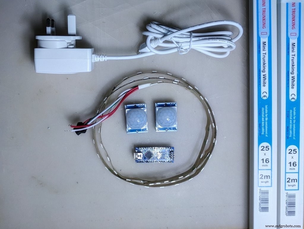
Components and supplies
| × | 1 | ||||
| × | 1 | ||||
| × | 2 | ||||
| × | 1 | ||||
| × | 2 |
Necessary tools and machines
 |
| |||
| ||||
 |
| |||
| ||||
 |
|
About this project
My staircase has claimed a broken toe some time ago. Fortunately, it wasn’t my toe, but I feel for the poor fella. The toe is OK now, but it got me thinking, is there anything I could do to reduce the risk of dealing with another victim? Plus if I could do this on the cheap, that would be super!
I created this tutorial for my personal blog (NotEnoughTech.com) where you will find more details about the build.
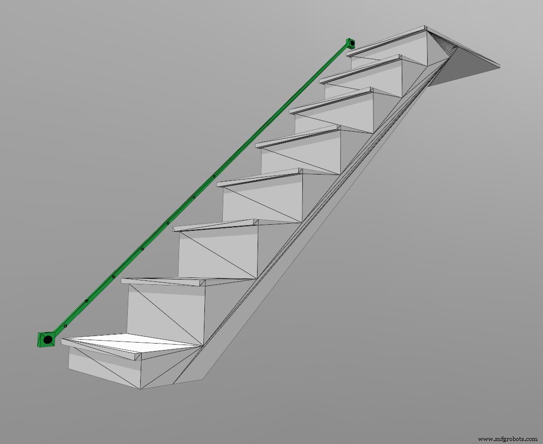
I came up with a rough sketch of what I have in mind just by staring at the staircase. To create nice lighting effect and keep things tidy, I would run the lights on the right side of the stairs. To trigger the lights automatically, I will need motion sensing.
The best layout I could come up with would be enclosed in some sort of trunking, with two LED’s per step. I have 13 steps which means I would need a total of 26 RGB LEDs to create the staircase RGB LED lighting.
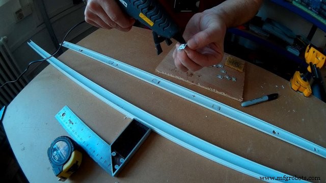
Cable Trunking
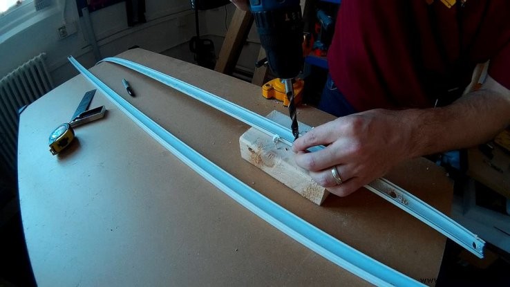
Let’s start with the trunking. I know, that steps are 30 cm apart so I need 2 holes for each step – 15 cm apart. Drill it in the shallow end otherwise (8-10mm drill), you will have a hard time getting the LEDs inside.
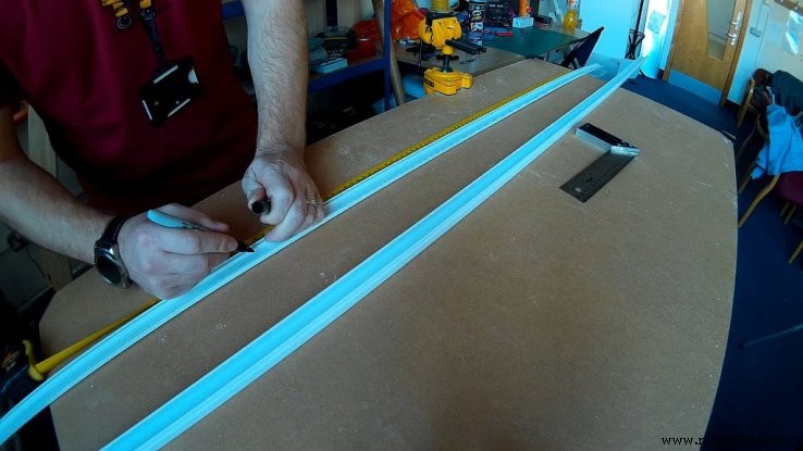
While you at it, you may as well drill the mounting holes (4mm). I found 5 per 2 m trunking to be sufficient. Make sure you have a mounting hole next to each end. If you know the dimensions of the PIR sensor enclosure, you can cut the trunking to size. I didn’t and I ended up cutting it later. Doing this in advance will save you time. Taper the ends of the trunking so the top edge and bottom edge finished perpendicular to the floor.
To join the trunking with a minimal gap, I cut one part shorter, so the cover with LEDs would overlap the joint.
Test the LED strip first to make sure all works great, then cut the strip down to individual pieces (pay attention to markings, mind the orientation of the LEDs – it’s IMPORTANT). Mark out the directions inside of the trunking before you proceed.
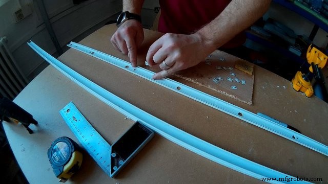
Mark:
- the direction of the input/output wire
- ground side
- positive side
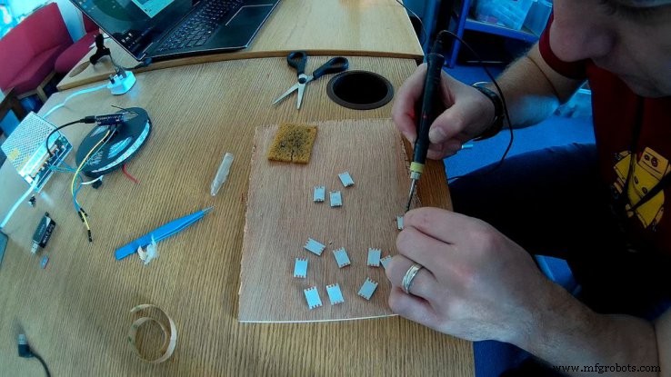
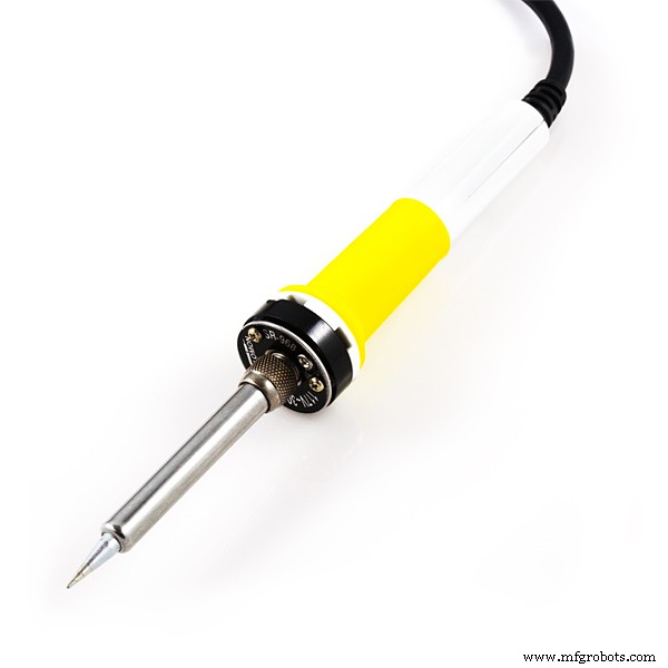
Before you glue down the LEDs, use a soldering iron to prep the contact points. It’s quicker this way. Make sure each side has a small blob of solder on the contact. If your LEDs strips come with 3M adhesive, remove the adhesive first.
Glue down the LEDs, minding the orientation. Be sure to follow this orientation across each trunking. If you tapered the ends, you won’t be able to change the order of the trunking anymore.
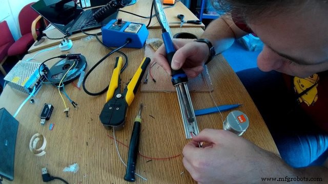
Soldering
This is the time-consuming part. Each LED needs 3 wires between each other. To make your job easier later, be consistent with a colour coding. Pre-cut the wire to even pieces and start connecting the LEDs. Leave a tiny slack, but don’t be excessive. I would advise you to glue down the wires in between the LEDs otherwise you will end up snagging it when closing the trunking.
Extend the VCC and GND at each end, in addition to this, the joining parts will need the data wire.
PIR sensorsI found a nice enclosure on thingyverse.com which I have printed out and made a small incision to allow wires to go inside. I used jumper wires to connect the pins. I removed the plastic separators from the pins to bend the pins sidewise. This way the sensor is sitting flushed with the back plate. You can power the sensor from the LED’s power rails.
The top sensor has to have a cable, that runs all the way (unless your Arduino is at the top, then flip the scenario) across the trunking. I split all my wires and used the jumper connections, so I could separate the trunking for transport. This way I can assemble the pieces at will, by connecting 4 cables (VCC, GND, DATA, PIR).
The bottom sensor is linked directly to the Arduino. I also ended up using the power rails of Arduino Nano to power it.
SchematicsThere are few things to remember. First, you have to share the common ground with Arduino so the LED data signal was correct. There are many ways of achieving this setup. I used jumper wires at first for testing and then I made a small PCB which has an Arduino Fixed to it, and all the cables fixed to it.
I have harvested a spare mini-USB cable and connected the RED and BLACK strains into the power. This way the voltage is regulated, it’s not advisable to power the Nano through the pins. The big advantage of keeping your cables neat is that you can fit the Nano inside the trunking.
To drive 26 LEDs I needed about 300mA at peak time, which means almost any USB charger will be strong enough to drive it. I used the other part (USB-A) of the cable to create an extension that will go from the mains to the Arduino and LEDs.
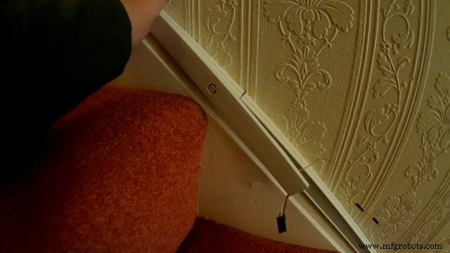
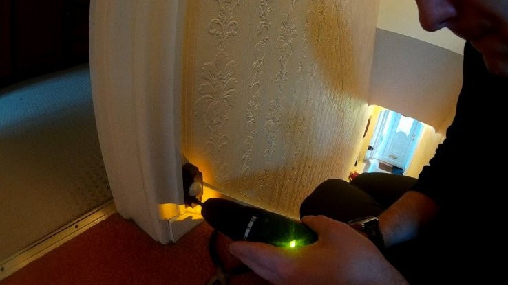
Mounting the Staircase RGB LED LightingStart from the top, this way the gravity won’t get in your way. Affix the wider trunking to the wall using screws. Pay attention to the ends, make sure that mounting screws are reasonably close to each end. Once happy with the result mount the PIR and drag the cables out through the holes.
Connect the cables for LEDs and work your way down to close the trunking, making sure that cables are not snagged inside. I used the leftover from the trunking to put the Arduino Nano inside. It’s longer than microcontroller itself, and it has an access hole at the bottom for the power lead.
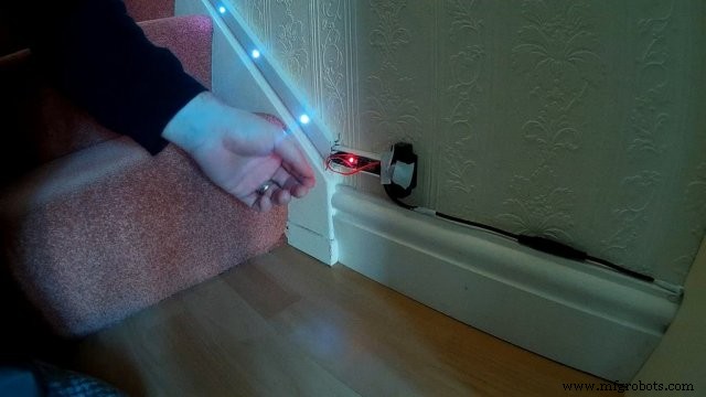
You will see that I have a power connector. I connected it this way, as there is no easy way of reprogramming the board, if you want to get fancy, you can make a socket that would house the Arduino Nano, making it completely removable.
Lastly, I cleaned up the cables and clamped the power wire to the skirting board for nearly invisible effect.
Code
The Arduino Code
An excellent base code written by Dean Montgomery with lots of effects.https://github.com/dmonty2/ArduinoMotionStairLights/blob/master/ArduinoMotionStairLights.inoCustom parts and enclosures
PIR Sensor case
CAD file on thingiverse.comSchematics
Schematics that shows how to connect everything (replace the battery with the relevant 5V power source)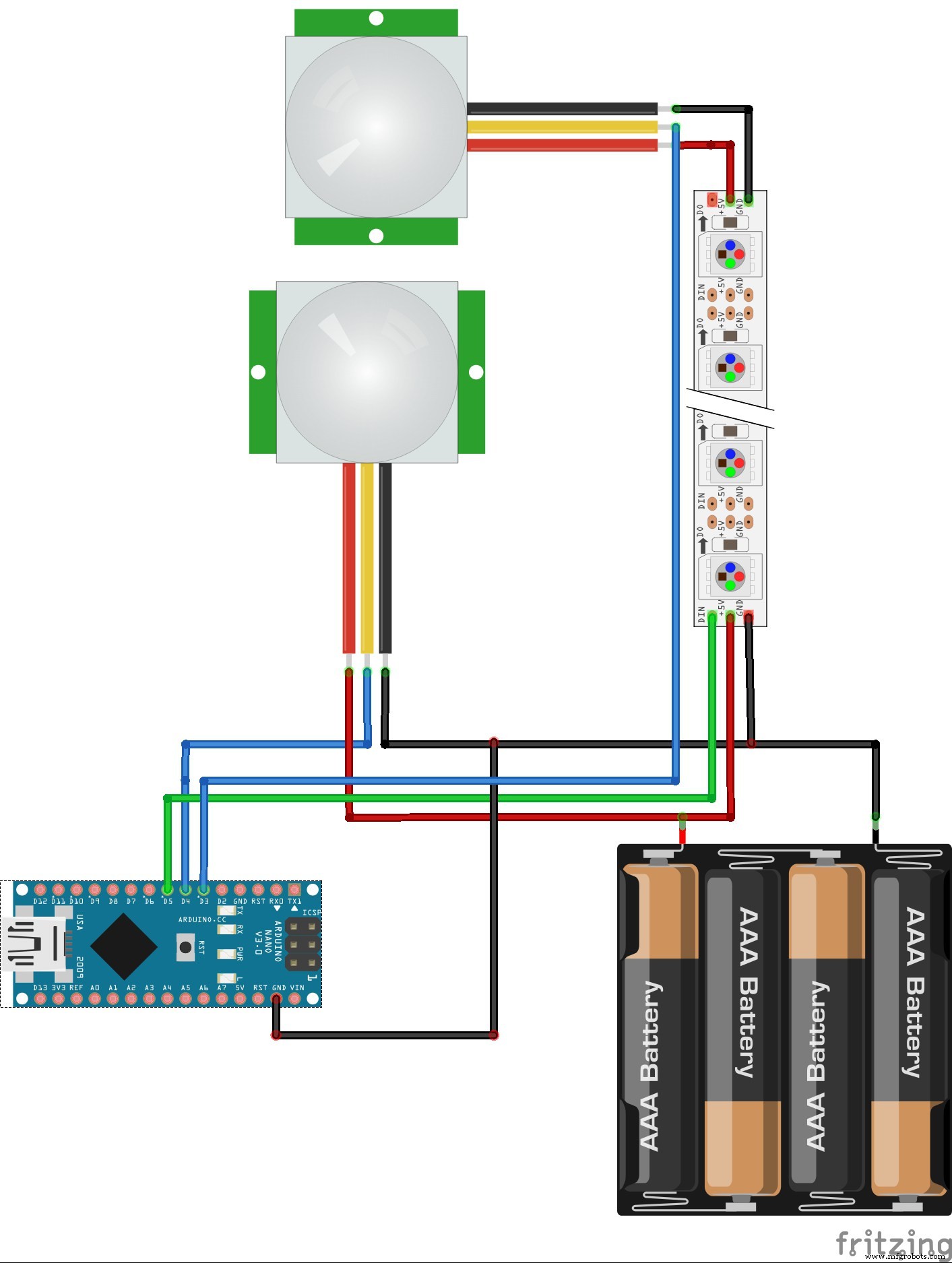
Manufacturing process
- Revitalize Old Remote Controls: Build DIY Smart Devices with Arduino
- Single-LED Light Painting: Build Dynamic Images with a DIY Motorized System
- DIY Hot Glue LED Matrix Lamp – Build Your Own Colorful Display
- Arduino RGB LED Color Mixer – Beginner‑Friendly DIY Project
- Outdoor DMX-Enabled RGB LED Flood Lights – Affordable & High-Performance
- Smart Arduino-Powered Automated Parking Garage System
- RGB LED Backlight with MSGEQ7 Audio Visualizer for TV and Desk
- Arduino-Driven LED Candle Lights: DIY Smart Lighting Project
- LED Whack‑a‑Mole Game with Arduino Uno – Interactive LED and Joystick Project
- Build an 8x8x8 RGB LED Cube with Arduino – DIY Guide