


Single-LED Light Painting: Build Dynamic Images with a DIY Motorized System
Components and supplies
| × | 2 | ||||
 |
| × | 2 | |||
| × | 1 | ||||
 |
| × | 1 | |||
| × | 1 |
Necessary tools and machines
 |
|
Apps and online services
 |
| |||
| ||||
 |
|
About this project
Idea
After watching several videos and seeing numerous articles about light painting, I decided to give it a try. Light painting involves using a camera with a very long exposure time to capture a small light source. This allows for a single of light to become strung out to a long streak in a single image.
But what if someone wants to create a more detailed picture or use many different colors? This is how I came up with the idea to build a 2-axis CNC machine that has a single RGB LED that can change color and “paint” an image.
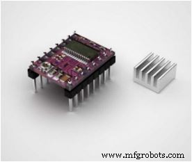
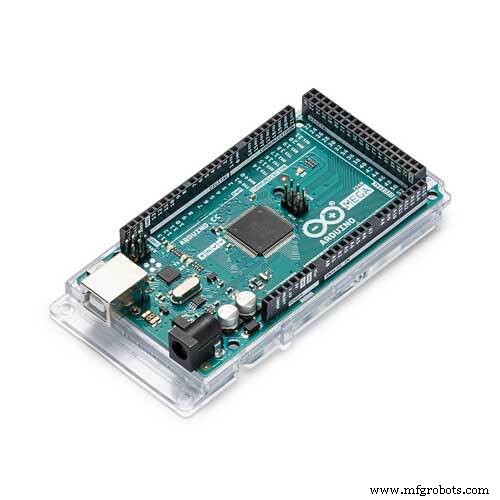
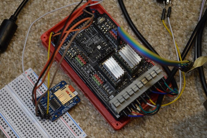
This project would require four main components to work: a 2-axis CNC machine, RGB LED, SD card, and a camera that is capable of taking long-exposure shots. First, the Arduino Mega would read the SD card and find a bitmap to print.
Then, it would go across horizontally and light up the corresponding LEDs while also moving down a row each time the image’s width is exceeded. Last, it will wait a bit and then search for the next bitmap, finally stopping whenever there aren’t any more images to create.
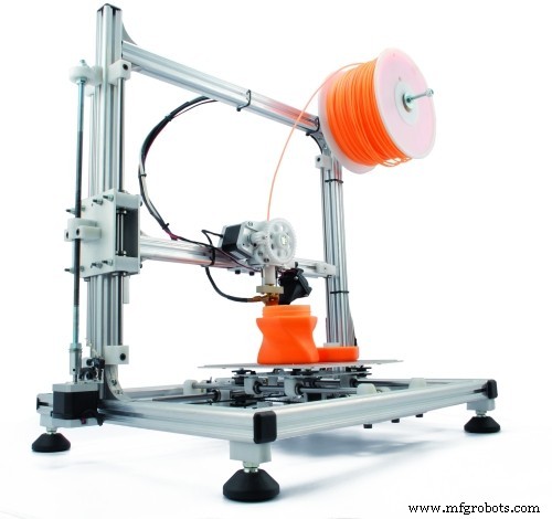
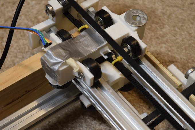
Constructing the RigDue to my experience designing and building CNC machine, this step wasn’t too difficult. I wanted to make something modular that could also be expanded for other projects, so I settled on a simple design that uses two timing belts attached to crossbars that move along parallel aluminum extrusions.

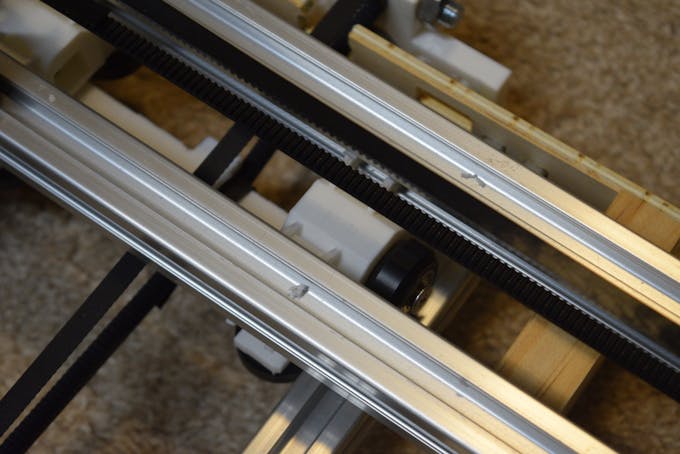
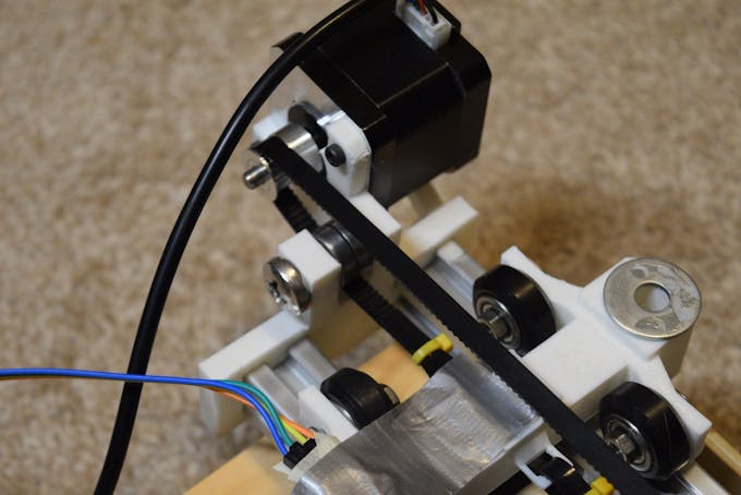
This lets the length of each axis be very customizable. The ends of the X-axis have 3D-printed endcaps on them, one of which has a mount for the X-axis stepper motor and bearing.
I chose the bitmap file format due to its simplicity and how easily it’s able to be read. Based on the file format, there are a few important addresses in the file itself that must be read. These are 0x12 (width), 0x16 (height), 0x1C (color depth), 0xA (location of pixel data), and finally 0x36 (where the pixel data usually is).
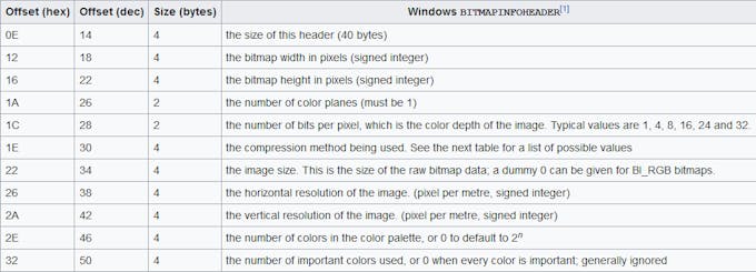
The data is read in chunks of either two or four bytes (16 or 32 bits), which also advances the pointer to the next address. The read function goes through and grabs all of the important data, including offsets and sizes. Then it goes through and reads each pixel, row by row.
Preparing the Images
Since most cameras are limited to a maximum of 30 seconds of exposure time, there is a limit of about 288 total pixels that can be displayed in that amount of time. This equates to about an 18 x 16 image. To make my images, I loaded up gimp and began to create very simple pixel art. These included a Pokéball, heart, and a jumping Mario. Then I placed these three images into a directory called “bitmaps” in the root directory of the SD card. The program reads all of the images from this folder.
Painting ProgramSince stepper motors have no internal positioning feedback system, their positions must be tracked by software. The program I wrote keeps track of the LED’s position with a grid system to allow for easy scaling. When the Arduino Mega starts up, the stepper positions are set to 0, 0 and then the first image is found and read. Then, the LED blinks five times to let the photographer know it is almost time to start capturing. The bitmap is read by first looping through each row, and within each row, each column is read. By knowing the current row and column, the stepper motors can be moved to those same positions. At each position, the LED is changed to the color of that corresponding pixel.
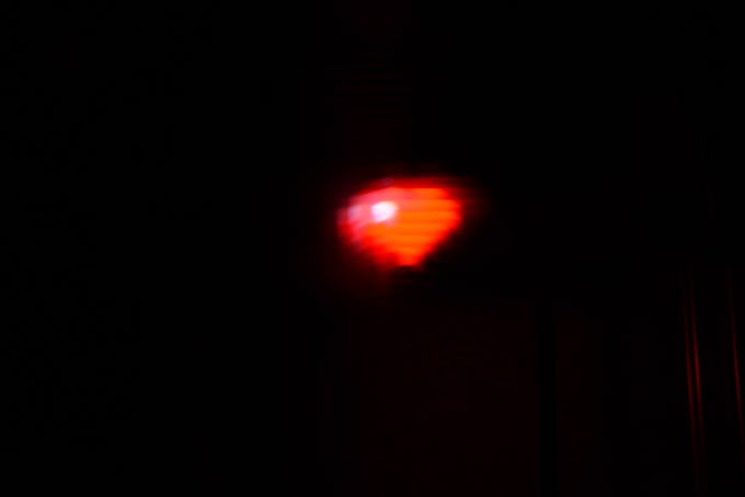
(re)-Creating an ImageAfter inserting the SD card and plugging in a 12v power source for the motors, it was time to turn on the machine. On my camera, I set it for a 20-second exposure time, an aperture of F36, ISO of 100, and an exposure compensation of -5 stops to minimize ghosting effects. The first image drawn was a pokeball, seen here:

Although it is a little bit blurry, the shape can still be clearly seen. Then it created a heart bitmap:
Because this image was only 9 by 9 pixels, each individual pixel is a lot less defined. Lastly, I painted a picture of Mario jumping:
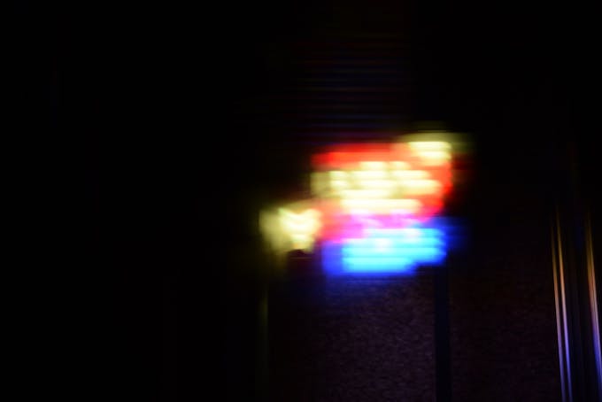
This picture has heavy ghosting, mainly due to the abundance of brightly colored pixels.
Future Ideas for ImprovementsThe light paintings I created turned out much better than I had initially thought they would, but there is still room for improvements. The main thing I would like to do is reduce the amount of blur by having the LED move while darkened and then only light up when still. This technique would greatly improve the clarity of the recreated images.
Code
- Light Painting Program
Light Painting ProgramC/C++
//Bitmap reading function partially from Adafruit

#include <SD.h>
#include <SPI.h>
#include "DRV8825.h"

#define MOTOR_STEPS 200
#define RPM 150
#define MICROSTEPS 4

//pin definitions
#define STEPPER_X_DIR 7
#define STEPPER_X_STEP 6
#define STEPPER_X_EN 8
#define STEPPER_Y_DIR 4
#define STEPPER_Y_STEP 5
#define STEPPER_Y_EN 12

#define X 0
#define Y 1

#define X_DIR_FLAG -1 //1 or -1 to flip direction
#define Y_DIR_FLAG 1 //1 or -1 to flip direction

#define STEPS_PER_MM (3.75 * MICROSTEPS) //steps needed to move 1mm
#define SPACE_BETWEEN_POSITIONS 5 //5mm per move

#define R A0
#define G A1
#define B A2

#define SD_CS 22

int currentPositions[] = {0, 0};

DRV8825 stepperX(MOTOR_STEPS, STEPPER_X_DIR, STEPPER_X_STEP, STEPPER_X_EN);
DRV8825 stepperY(MOTOR_STEPS, STEPPER_Y_DIR, STEPPER_Y_STEP, STEPPER_Y_EN);

void setup() {
  Serial.begin(115200);
  init_steppers();
  SD.begin(SD_CS);
  createBitmaps();
  stepperX.disable();
  stepperY.disable();
  while(1);
}

void loop() {
}

void createBitmaps(){
  File dir = SD.open("bitmaps");
  while(true){
    File bitmap = dir.openNextFile();
    if(!bitmap){
      break;
    }
    paintBitmap(bitmap);
    delay(15000);
  }

}

#define BUFFPIXEL 20
void paintBitmap(File bmpFile){
  int bmpWidth, bmpHeight;
  uint8_t bmpDepth;
  uint32_t bmpImageOffset;
  uint32_t rowSize;               // Not always = bmpWidth; may have padding
  uint8_t  sdbuffer[3 * BUFFPIXEL]; // pixel buffer (R+G+B per pixel)
  uint8_t  buffidx = sizeof(sdbuffer); // Current position in sdbuffer
  boolean  goodBmp = false;       // Set to true on valid header parse
  boolean  flip = true;        // BMP is stored bottom-to-top
  int      w, h, row, col;
  uint8_t  r, g, b;
  uint32_t pos = 0, startTime = millis();

  Serial.println();
  Serial.print("Loading image '");
  Serial.print(bmpFile.name());
  Serial.println('\'');

  // Open requested file on SD card

  // Parse BMP header
  if (read16(bmpFile) == 0x4D42) { // BMP signature
    Serial.print("File size: "); Serial.println(read32(bmpFile));
    (void)read32(bmpFile); // Read & ignore creator bytes
    bmpImageOffset = read32(bmpFile); // Start of image data
    Serial.print("Image Offset: "); Serial.println(bmpImageOffset, DEC);
    // Read DIB header
    Serial.print("Header size: "); Serial.println(read32(bmpFile));
    bmpWidth = read32(bmpFile);
    bmpHeight = read32(bmpFile);
    if (read16(bmpFile) == 1) { // # planes -- must be '1'
      bmpDepth = read16(bmpFile); // bits per pixel
      Serial.print("Bit Depth: "); Serial.println(bmpDepth);
      if ((bmpDepth == 24) && (read32(bmpFile) == 0)) { // 0 = uncompressed

        goodBmp = true; // Supported BMP format -- proceed!
        Serial.print("Image size: ");
        Serial.print(bmpWidth);
        Serial.print('x');
        Serial.println(bmpHeight);

        // BMP rows are padded (if needed) to 4-byte boundary
        rowSize = (bmpWidth * 3 + 3) & ~3;

        // If bmpHeight is negative, image is in top-down order.
        // This is not canon but has been observed in the wild.
        if (bmpHeight < 0) {
          bmpHeight = -bmpHeight;
          flip = false;
        }

        // Crop area to be loaded
        w = bmpWidth;
        h = bmpHeight;

        if(bmpWidth*bmpHeight>290){ //Too large
          Serial.println("File is too large to be printed.");
          return;
        }

        for(uint8_t i=0; i<5;i++){
          analogWrite(R, 150);
          delay(500);
          analogWrite(R, 0);
          delay(500);
        }
        for (row = 0; row<h; row++) { // For each scanline...
          moveToPosition(0, row);
          // Seek to start of scan line.  It might seem labor-
          // intensive to be doing this on every line, but this
          // method covers a lot of gritty details like cropping
          // and scanline padding.  Also, the seek only takes
          // place if the file position actually needs to change
          // (avoids a lot of cluster math in SD library).
          if (flip) // Bitmap is stored bottom-to-top order (normal BMP)
            pos = bmpImageOffset + (bmpHeight - 1 - row) * rowSize;
          else     // Bitmap is stored top-to-bottom
            pos = bmpImageOffset + row * rowSize;
          if (bmpFile.position() != pos) { // Need seek?
            bmpFile.seek(pos);
            buffidx = sizeof(sdbuffer); // Force buffer reload
          }

          // optimize by setting pins now
          for (col = 0; col<w; col++) { // For each pixel...
                          // Time to read more pixel data?
            if (buffidx >= sizeof(sdbuffer)) { // Indeed
              bmpFile.read(sdbuffer, sizeof(sdbuffer));
              buffidx = 0; // Set index to beginning
            }

            // Convert pixel from BMP to TFT format, push to display
            b = sdbuffer[buffidx++];
            g = sdbuffer[buffidx++];
            r = sdbuffer[buffidx++];

            moveToPosition(col, row);
            activateLED(r,g,b);
            // optimized!
            //tft.pushColor(tft.Color565(r,g,b));
          } // end pixel
          analogWrite(R, 0);
          analogWrite(G, 0);
          analogWrite(B, 0);
        } // end scanline
        Serial.print("Loaded in ");
        Serial.print(millis() - startTime);
        Serial.println(" ms");
      } // end goodBmp
    }
  }

  bmpFile.close();
  moveToPosition(0,0);
  if (!goodBmp) Serial.println("BMP format not recognized.");
}

uint16_t read16(File f) {
  uint16_t result;
  ((uint8_t *)&result)[0] = f.read(); // LSB
  ((uint8_t *)&result)[1] = f.read(); // MSB
  return result;
}

uint32_t read32(File f) {
  uint32_t result;
  ((uint8_t *)&result)[0] = f.read(); // LSB
  ((uint8_t *)&result)[1] = f.read();
  ((uint8_t *)&result)[2] = f.read();
  ((uint8_t *)&result)[3] = f.read(); // MSB
  return result;
}

void activateLED(int r, int g, int b){
  Serial.print(F("LED has value of: "));
  Serial.print(r);
  Serial.print(", ");
  Serial.print(g);
  Serial.print(", ");
  Serial.println(b);
  analogWrite(R, r);
  analogWrite(G, g);
  analogWrite(B, b);
}

void moveToPosition(int x, int y){
  int newPosX = (x-currentPositions[X])*STEPS_PER_MM*X_DIR_FLAG*SPACE_BETWEEN_POSITIONS;
  int newPosY = (y-currentPositions[Y])*STEPS_PER_MM*Y_DIR_FLAG*SPACE_BETWEEN_POSITIONS;
  stepperX.move(newPosX);
  stepperY.move(newPosY);
  currentPositions[X] = x;
  currentPositions[Y] = y;
  Serial.print("Stepper positions: "); Serial.print(currentPositions[X]); Serial.print(", "); Serial.println(currentPositions[Y]);
}

void init_steppers(){
  stepperX.begin(RPM);
  stepperX.setEnableActiveState(LOW);
  stepperX.enable();
  stepperX.setMicrostep(MICROSTEPS);
  stepperY.begin(RPM);
  stepperY.setEnableActiveState(LOW);
  stepperY.enable();
  stepperY.setMicrostep(MICROSTEPS);
}
Custom parts and enclosures
Schematics
Manufacturing process
- Why Designers Are Returning to Natural Materials in Product Design
- Transfer Temperature & Humidity Data Between Two Arduinos Using Firebase
- Revitalize Old Remote Controls: Build DIY Smart Devices with Arduino
- Wireless Data Transfer via LED (Li-Fi) – Arduino Project
- Seamless LED Brightness Control Using Bolt IoT and Arduino UNO
- Infrared Eye‑Motion Tracking with Arduino Pro Mini – LED Control Demo
- Build a 48x8 Scrolling LED Matrix with Arduino – Step-by-Step Guide
- Smart Staircase RGB LED Lighting System – Motion-Activated & Easy to Install
- Master WS2812B LED Control with Arduino – Step‑by‑Step Guide
- DIY LED Heat Sink: Build a Professional-Grade Cooling Solution