


LED Whack‑a‑Mole Game with Arduino Uno – Interactive LED and Joystick Project
Components and supplies
 |
| × | 1 | |||
| × | 7 | ||||
 |
| × | 7 | |||
| × | 1 | ||||
 |
| × | 8 | |||
 |
| × | 4 |
About this project
This was my first Arduino project, I built it based off what I learned from the early on tutorials on LED's and basic controls.
This "Whack-a-mole" game uses 7 LED's, and a joystick. There are 4 "moles", represented by the 2nd, 3rd, 4th, and 5th lights from the left on my board. One of the four lights will randomly light up and give a set amount of time to hit the corresponding direction on the joystick. I have arranged my lights so that, from left to right, the selections on the joystick are: left, up, down, right. This is just the convention that I chose, so creative and try other ones!
The two lights on the left are red and green, which indicate a incorrect or correct choice. The yellow light to the far right blinks the count for the current high score, and it indicates the score every time a run is over (whenever a wrong choice is made). Naturally, a new high score replaces the old one.
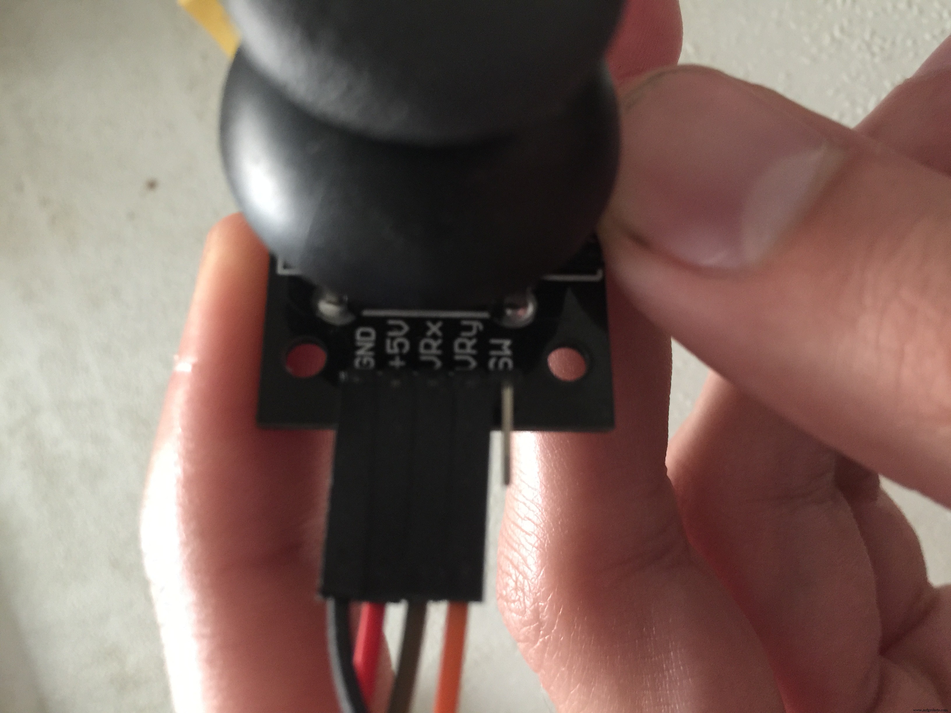
Perhaps the most complicated part of this project is the analog joystick. For both directions of the joystick, there are max values of 0 and 1024 (for mine, I had to use 1023, so if you aren't getting the selections correct, you can try that). I believe these values can be measured as well using a serial window. I simplified these input values using switch statements for both the x and y inputs. I am not sure if this is the best way to do it, but because I only needed the max values of each direction (i.e, only 4 options, 4 LED moles) I assigned integer values to each possibility: 1, 2, 3, 4 corresponding to Left, Right, Up, Down.
The difficulty levels that I have written into my code as constants, are the time in milliseconds that the person has to make a selection. You can mess around with these times to change the difficulty for your own preference. I thought about integrating a choice using buttons or maybe the joystick at the beginning of a turn, but it wasn't really worth the work as I feel it would be pretty complicated and not really user friendly.
By all means, let me know what modifications and improvements can be made! :)
Code
- WhackALED
WhackALEDArduino
// Whack a LED

// Joystick variables
int sX = A0;     //joystick x axis, analog input
int sY = A1;     //joystick y axis, analog input
int sSX;         //state of x, reading from sX
int sSY;         //state of y, reading from sY
int sS;          //converted state (may not be most efficient)

// Game variables
int rNum;        //random int choosing the random light to turn on
int wins=0;      //counting consecutive wins
int highScore=0; //saving the highest score of consecutive wins

// Difficulty constants, time to react
const int easy=1000;
const int medium=500;
const int hard=325;
const int stupid=250;


int ledPins[]={5,2,4,3,6,7,8}; //initializing led's
int pinCount=7;                //number of led pins

void setup() {

Serial.begin(9600);
pinMode(sX, INPUT);
pinMode(sY, INPUT);

for (int thisPin = 0; thisPin < pinCount; thisPin++) { //assigning all the pins as outputs in a for loop
    pinMode(ledPins[thisPin], OUTPUT);
  }
}

void loop() {

  rNum=random(4); //generating random choice
  delay(1000);
  digitalWrite(ledPins[rNum], HIGH); //lighting the randomly chosen bulb
  delay(stupid); //difficulty

  //stick stuff
  sSX = analogRead(sX); //reading x axis input
  delay(100);
  sSY = analogRead(sY); //reading y axis input

  //converting y and x inputs to 4 possibilities. 0 and 1023 are the maximum values on each axis of the joystick, as measured.
  sS=0;
  switch (sSX) {
  case 0:
  sS=1;      // Left
  break;
  case 1023:
  sS=2;      // Right
  break;
}
switch (sSY) {
  case 0:
  sS=3;      // Up
  break;
  case 1023:
  sS=4;      // Down
  break;
}

  digitalWrite(ledPins[rNum], LOW); //turning off the randomly selected bulb, after the joystick choice was made
  if (sS-1==rNum) //checking if the user input the correct direction of the lit bulb
  {
    wins++;
    for (int k=0; k<=3; k++) {     //blinking green light indicating correct choice
    digitalWrite(ledPins[4], HIGH);
    delay(50);
    digitalWrite(ledPins[4], LOW);
    delay(50);
    }
  }
  else
  {
    if (wins>highScore) { //if the consecutive wins are more than the previous highscore, the new highscore is set.
        highScore=wins;
        wins=0;
    }
    for (int i=0; i<=3; i++) {       //blinking red light indicating incorrect choice
      digitalWrite(ledPins[5], HIGH);
      delay(50);
      digitalWrite(ledPins[5], LOW);
      delay(50);
    }
    for (int w=0; w<highScore; w++) { //displaying via counting and blinking the high score on a yellow bulb.
        digitalWrite(ledPins[6], HIGH);
        delay(200);
        digitalWrite(ledPins[6], LOW);
        delay(200);
    }
  }
  }
Schematics
Everything should match the real picture of the project except for the joystick. My joystick has 5 pins, 4 or which I have used: named from top to bottom "GND", "+5V", "VRx", and "VRy". "GND" and "+5V" are connected to GND and 5V on the arduino, "VRx" and "VRy" are connected to A0 and A1.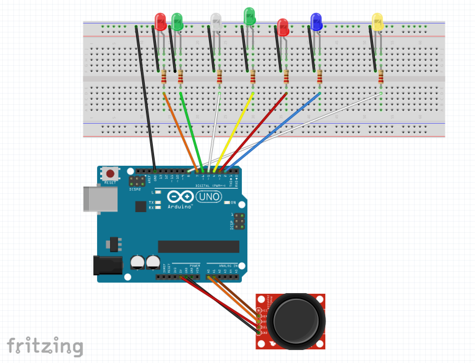 Everything should match the real picture of the project except for the joystick. My joystick has 5 pins, 4 or which I have used: named from top to bottom "GND", "+5V", "VRx", and "VRy". "GND" and "+5V" are connected to GND and 5V on the arduino, "VRx" and "VRy" are connected to A0 and A1.whack_a_mole_schematic_CBciL9GiCP.fzz
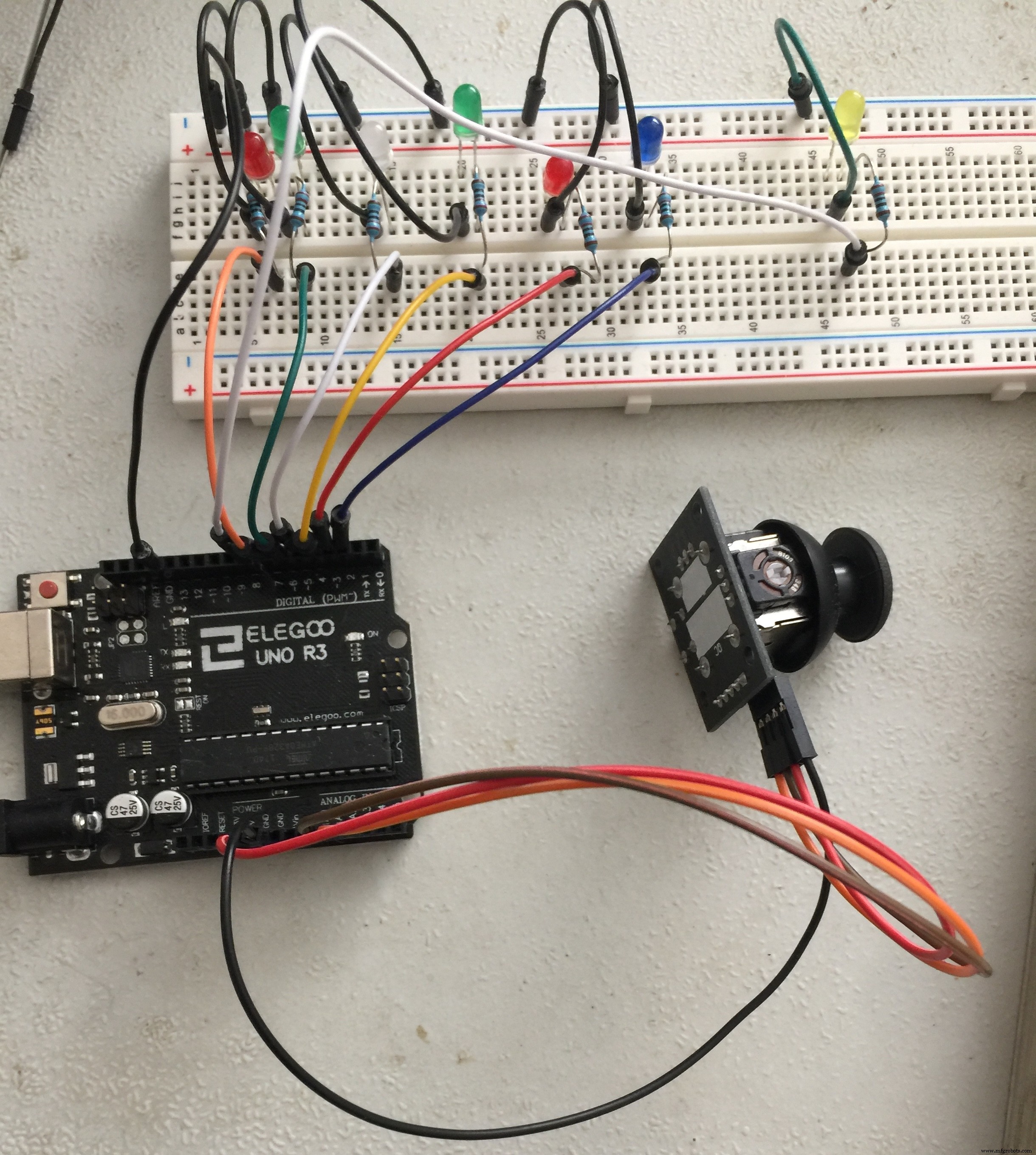
Manufacturing process
- Light‑Emitting Diodes: From Inception to 100‑Year Lifespans
- Wireless Data Transfer via LED (Li-Fi) – Arduino Project
- Build an Ambient Light Sensor with Photoresistor and LED: Step‑by‑Step Guide
- Arduino-Driven LED Candle Lights: DIY Smart Lighting Project
- Smart Staircase RGB LED Lighting System – Motion-Activated & Easy to Install
- Smart Traffic Light Control System with Real-Time Data
- DP-716 Emergency LED Light Circuit – Rechargeable 30‑LED Schematic & Build Guide
- Build Your Own LED Lights: A Complete DIY Step-by-Step Guide
- DIY LED Grow Light: The Ultimate Step‑by‑Step Guide for Home Greenhouse Success
- Mastering LED Strip Accessories: Connect, Control, and Customize Your Lighting