Build an Ambient Light Sensor with Photoresistor and LED: Step‑by‑Step Guide
Components and supplies
About this project
I’ve been using Arduino for a little while now and I’ve decided it’s past time to design my own project from scratch. I modified some circuits I found online from Alex Glow and Joe Coburn so they better suited this project. Please, if you find any problems, or think you found something that works better than my design, please comment below and I will get back to you.
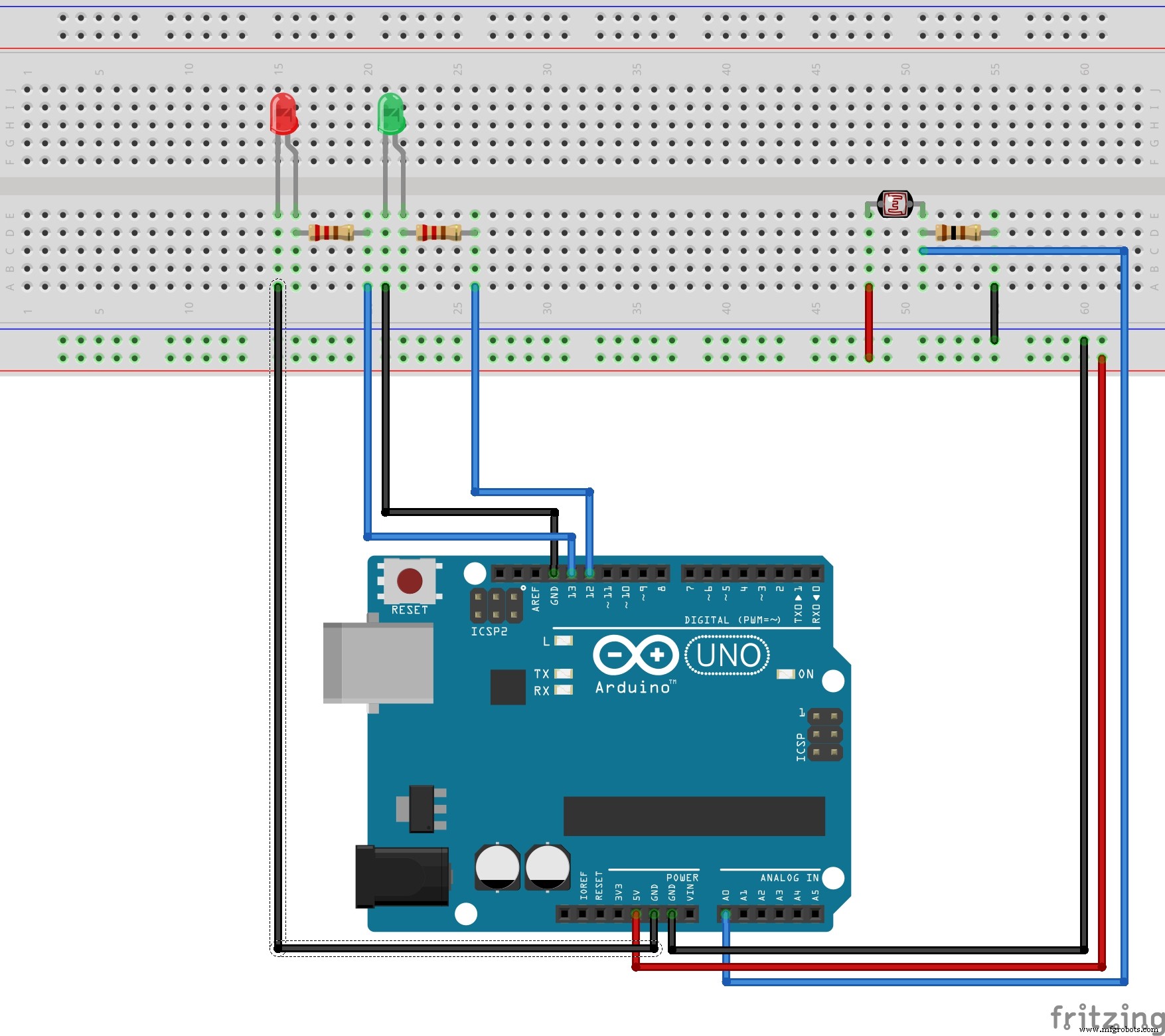
WiringI have a photo resistor wired into analog pin 0 (any analog pin would work) and a 5V on the right side of the breadboard. It runs through a grounded 1K ohm resistor. I wired an LED (any color) on the opposite side of the breadboard into digital pin 13 (any digital pin would work) and a grounded 220-ohm resistor (a 100-ohm would also work). Slightly to the right of the first LED a wired an LED of a different color the same way, just with a different digital pin.
How It WorksIf the photo resistor reads a value above 450, it prints “It is quite light!” on the serial monitor and turns all LEDs off, like this:
  if(light > 450) { // If it is bright...
       Serial.println("It is quite light!");
       digitalWrite(13,LOW); //turn left LED off
       digitalWrite(12,LOW); // turn right LED off
   }
If it reads a value between 230 and 450, it prints “It is average light!” on the serial monitor and turns on the left LED, like this:
   else if(light > 229 && light < 451) { // If it is average light...
       Serial.println("It is average light!");
      digitalWrite(13, HIGH); // turn left LED on
      digitalWrite(12,LOW);  // turn right LED off
   }
This only leaves us with values below 230 to account for. If a value is below 230, it prints “It is quite dark!” on the serial monitor and turns on both LEDs, like this:
   else { // If it's dark...
       Serial.println("It is pretty dark!");
       digitalWrite(13,HIGH); // Turn left LED on
       digitalWrite(12,HIGH); // Turn right LED on
   }
I added a delay of 1000 to the end of my loop to prevent an overload of information into the serial monitor, like this:
delay(1000); // don't spam the computer!
Make sure you look at the schematic and check your code before uploading or running anything.
Code
LED_PR_Light_ReadArduino
int light = 0; // store the current light value

void setup() {
    // put your setup code here, to run once:
    Serial.begin(9600); //configure serial to talk to computer
    pinMode(13, OUTPUT); // configure digital pin 13 as an output
    pinMode(12, OUTPUT); // configure digital pin 12 as an output
}

void loop() {
    // put your main code here, to run repeatedly:
    light = analogRead(A0); // read and save value from PR

    Serial.println(light); // print current light value

    if(light > 450) { // If it is bright...
        Serial.println("It is quite light!");
        digitalWrite(13,LOW); //turn left LED off
        digitalWrite(12,LOW); // turn right LED off
    }
    else if(light > 229 && light < 451) { // If it is average light...
        Serial.println("It is average light!");
       digitalWrite(13, HIGH); // turn left LED on
       digitalWrite(12,LOW);  // turn right LED off
    }
    else { // If it's dark...
        Serial.println("It is pretty dark!");
        digitalWrite(13,HIGH); // Turn left LED on
        digitalWrite(12,HIGH); // Turn right LED on
    }
    delay(1000); // don't spam the computer!
}
Schematics