


Secure Password-Based Door Lock with Arduino, Keypad & Linear Actuator
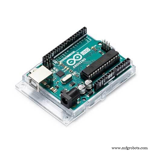
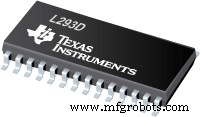
Components and supplies
 |
| × | 1 | |||
| × | 1 | ||||
 |
| × | 1 | |||
| × | 1 |
About this project
There are numerous websites that have posted this project & it is present on various youtube channels , and maybe even this website has a few of these. So, being honest, its nothing original. But I might be able to explain and display in a simpler and more informative manner.
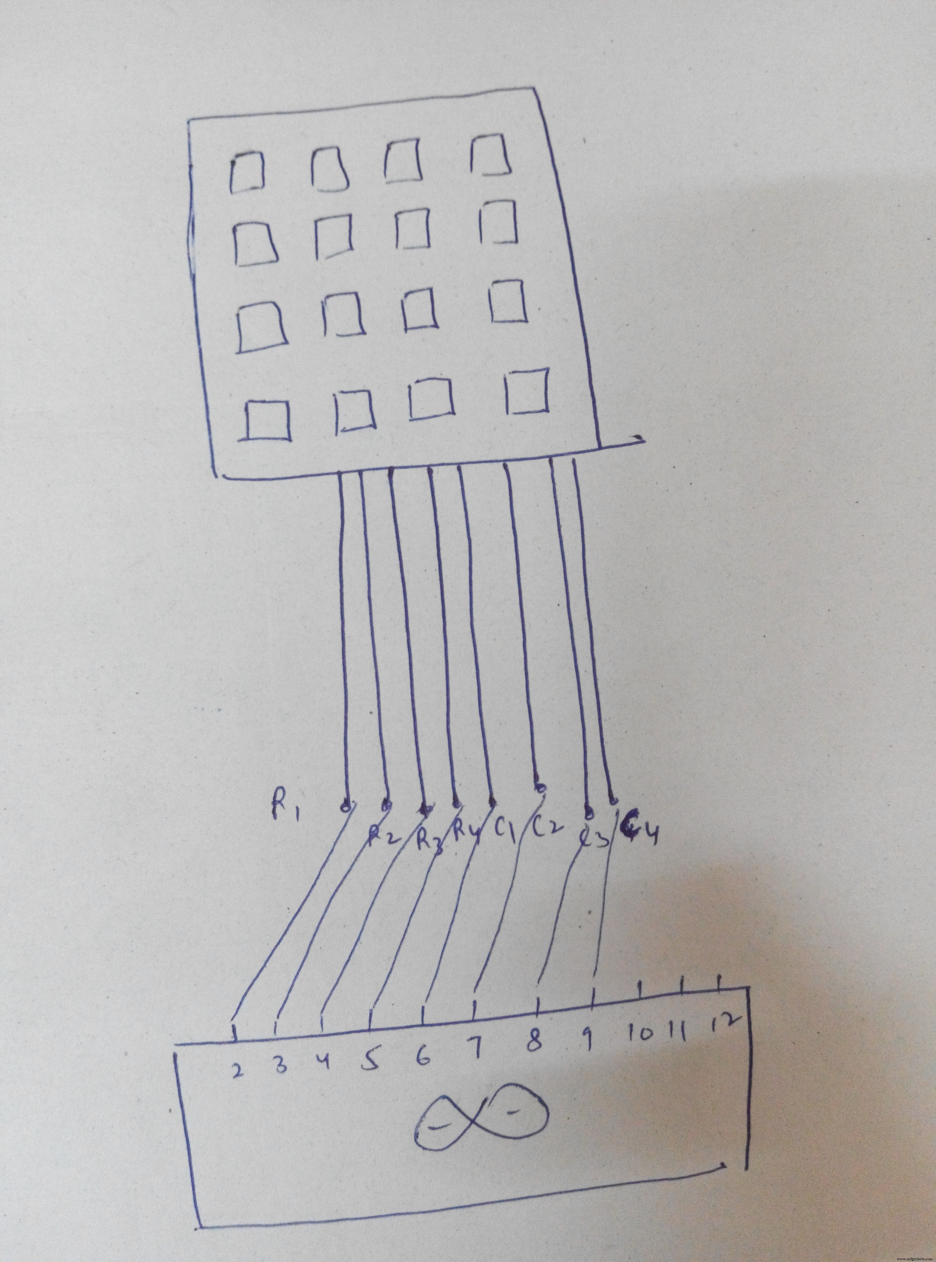
The major component of this project is the matrix keypad. I have used a 4x4 membrane keypad which looks like this:
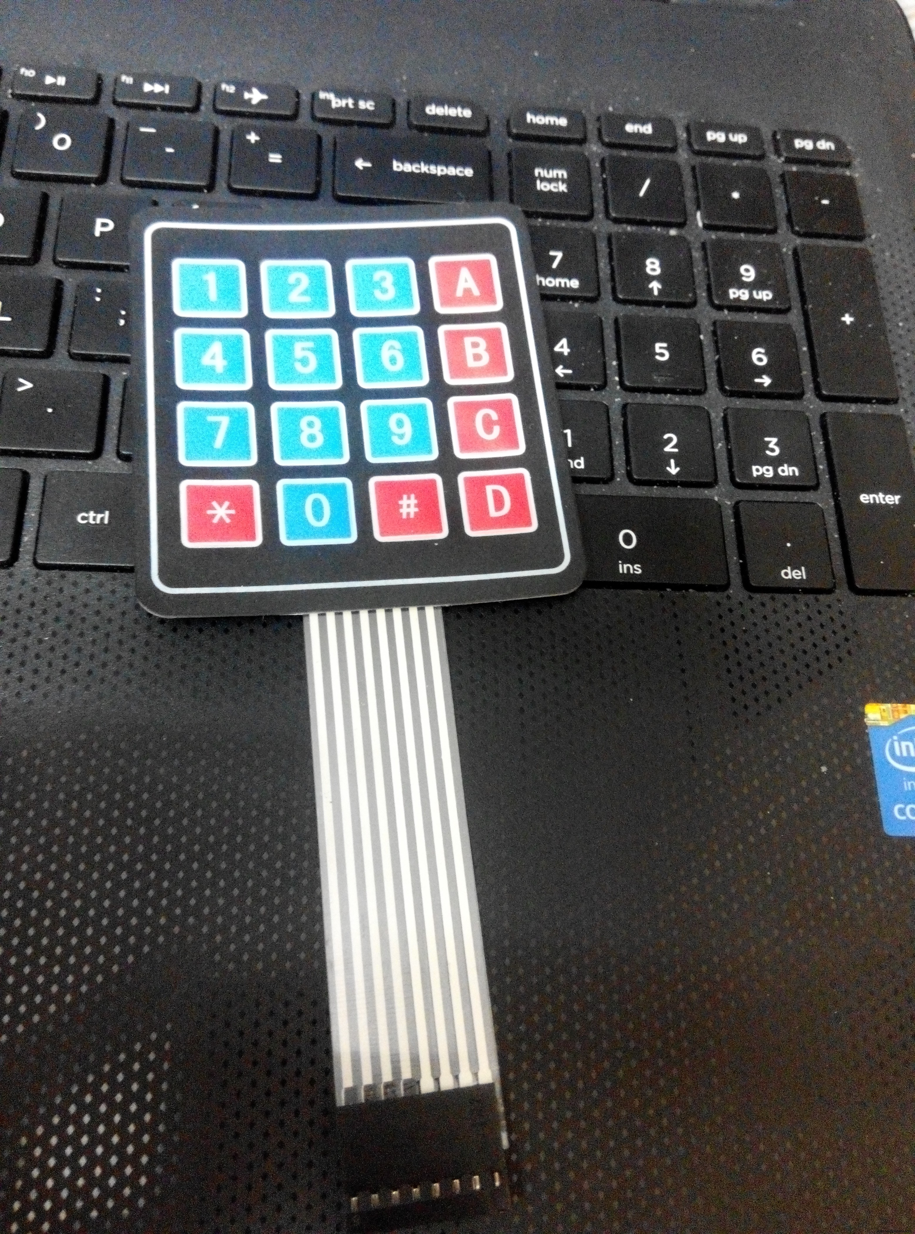
The keys on the keypad are basically push buttons. These button switches are 'closed' when pushed and once the force is released, they go back to their natural state i.e. 'open' .
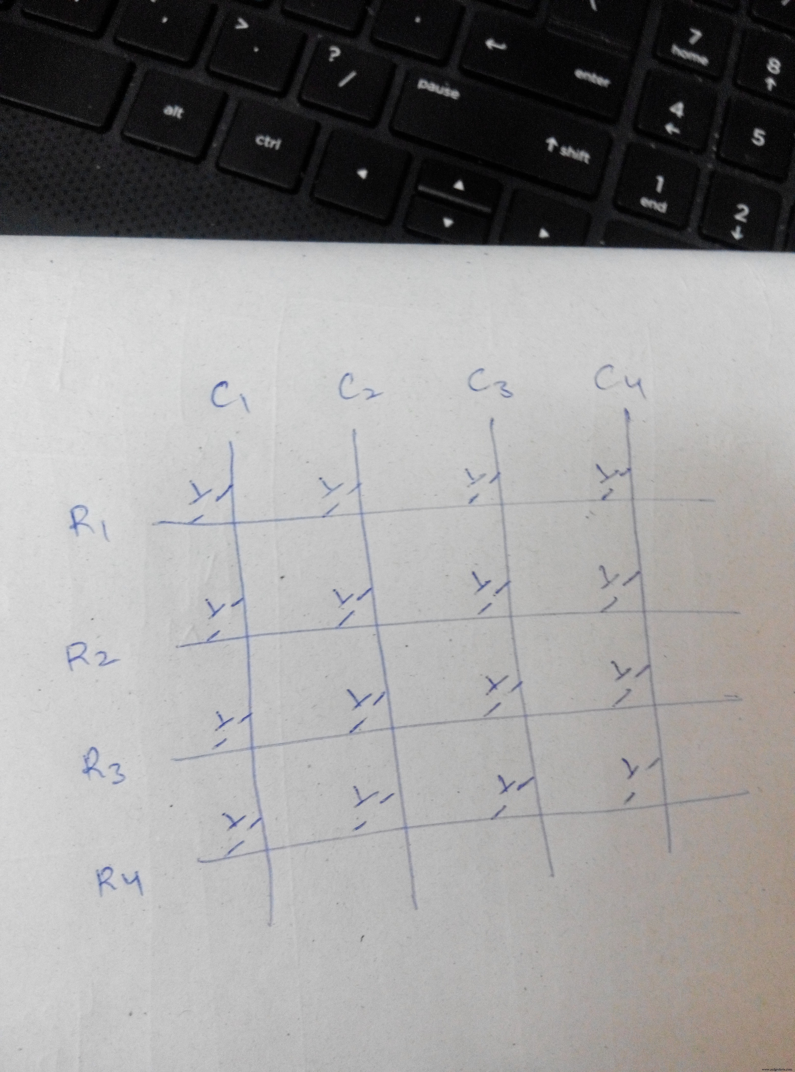
This is how the keypad is connected internally as rows and columns. When, suppose, 1 is pressed, column 1 and row 1 are connected together. When 9 is pressed r3 and c3 are connected together.
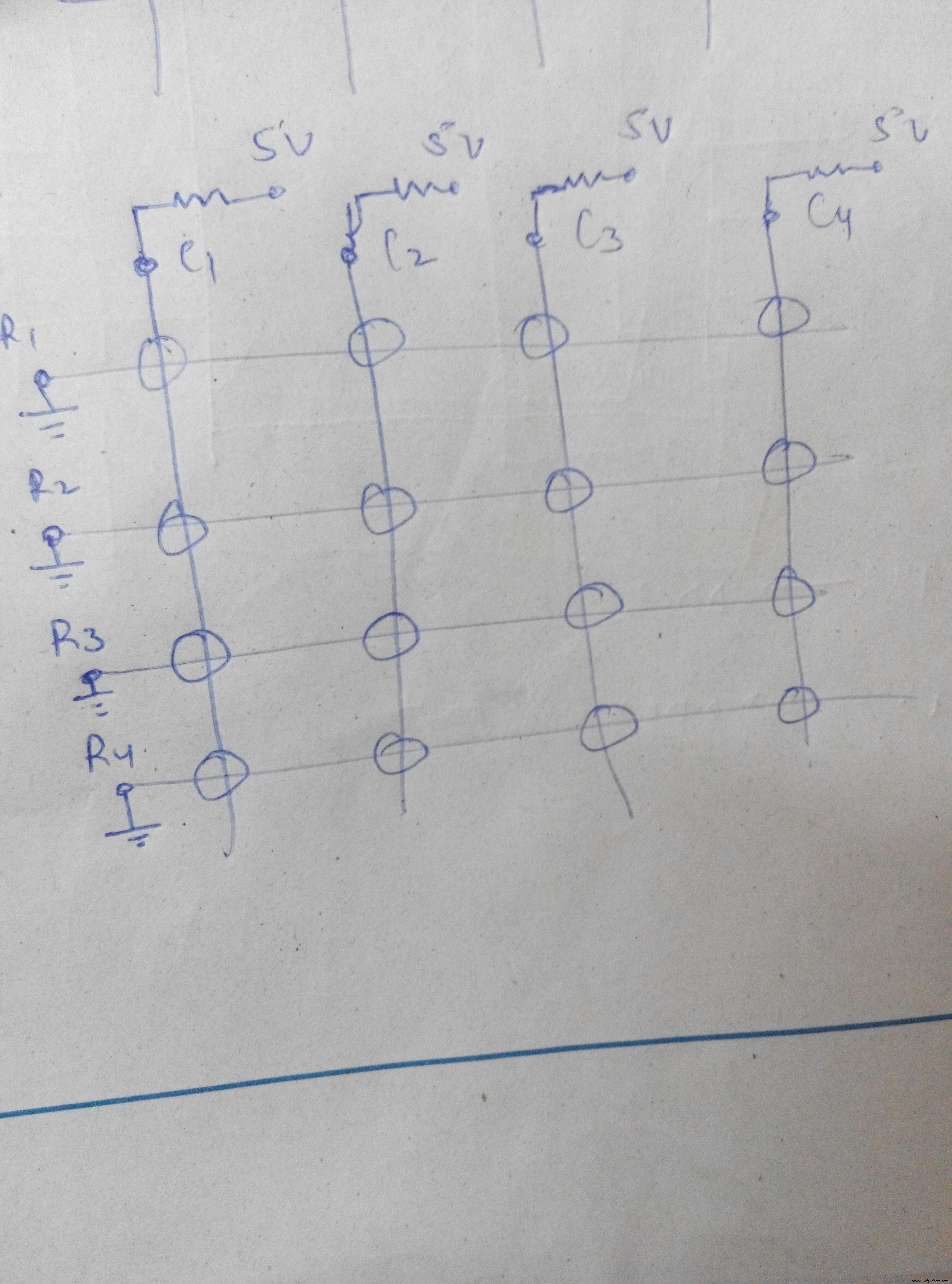
Scanning is done with 4 keys configured as outputs and 4 keys as inputs. I made all the columns the inputs using input pullup resistors, and all the rows the outputs. Using programming, all the rows are made LOW one by one, multiple times in a second. So, when a key is pressed, the corresponding column becomes LOW. The state of the input pins to which all the columns are connected, is read, multiple times. Whenever a LOW state is read, it means that a key in that column is pressed. If a certain row is low and at the same time a certain column is low, then the pressed key is determined.
For e.g. if 1 is pressed, column 1 will be low. And since each row is made LOW so so fast, one by one, even if you press the key for a very short span, row 1 will be found LOW sometime and it will be determined that 1 is pressed. If row1==low && column1==low, it means that 1 is pressed.
This is shown in code 1. I wrote this code myself because I wanted to upload it to stm32 board and the KEYPAD library wasn't compatible. With this code, you'll understand what I explained above. Or you can simply use the keypad library and run the 'customkeypad' example. Both will serve the same purpose. But that code won't explain you the working.
Using serial monitor, each key that is pressed is displayed on the screen. This is shown in video 1.
After the key determination works fine, its time to work on the password. Its so simple. What I did was - made a string "1234". This is the password that I had set. Now, I made another array. Whatever the key value is, its stored in this array. When count reaches 4, both the strings are compared. If they match - the password is correct, else not. This is shown in code 2. I connected an LED to the pin 11. So, that when the password is correct, it glows. It is shown in video 2.
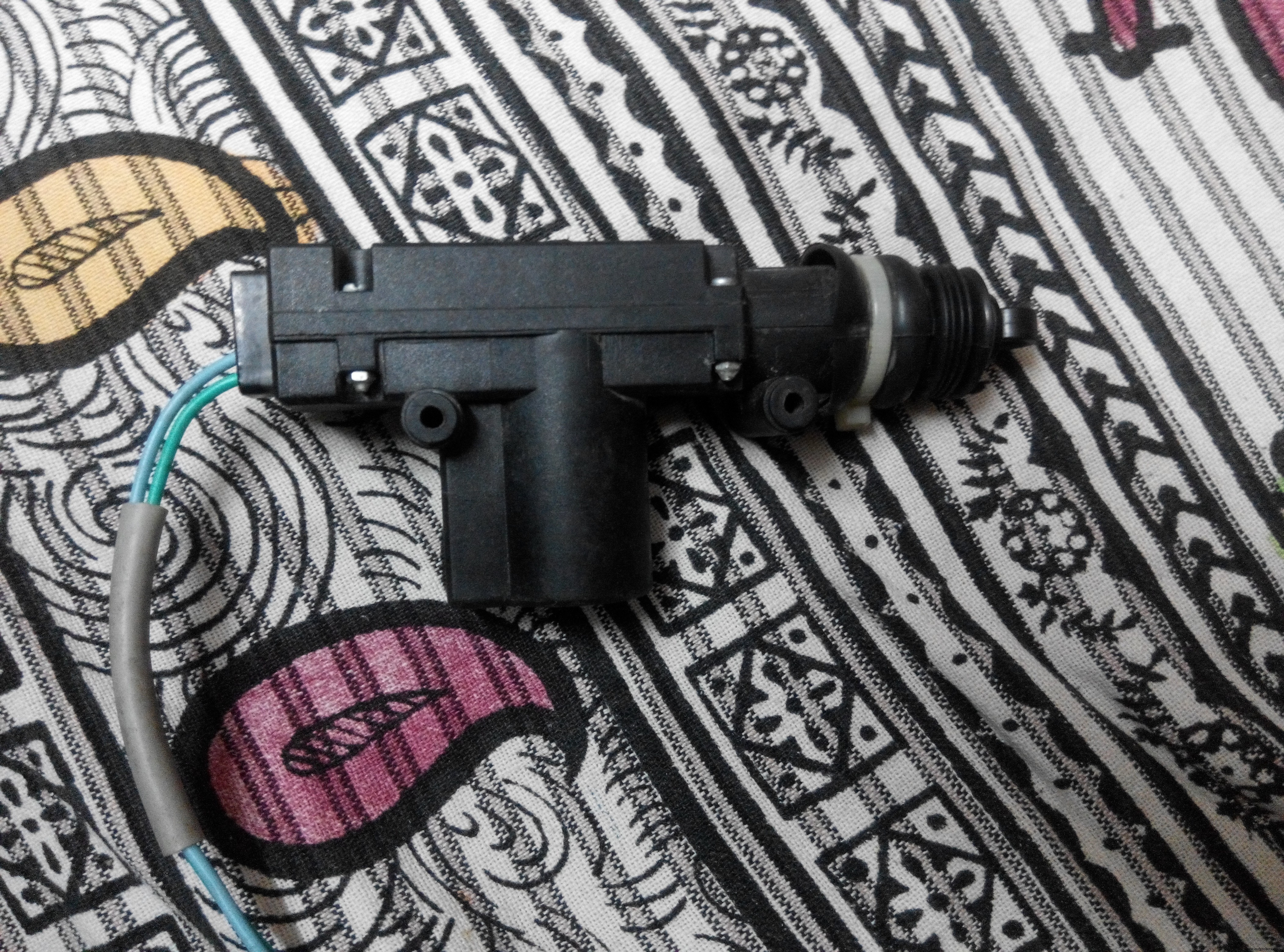
Now, the component that will be used as the lock: 12 V linear actuator. It looks like this.
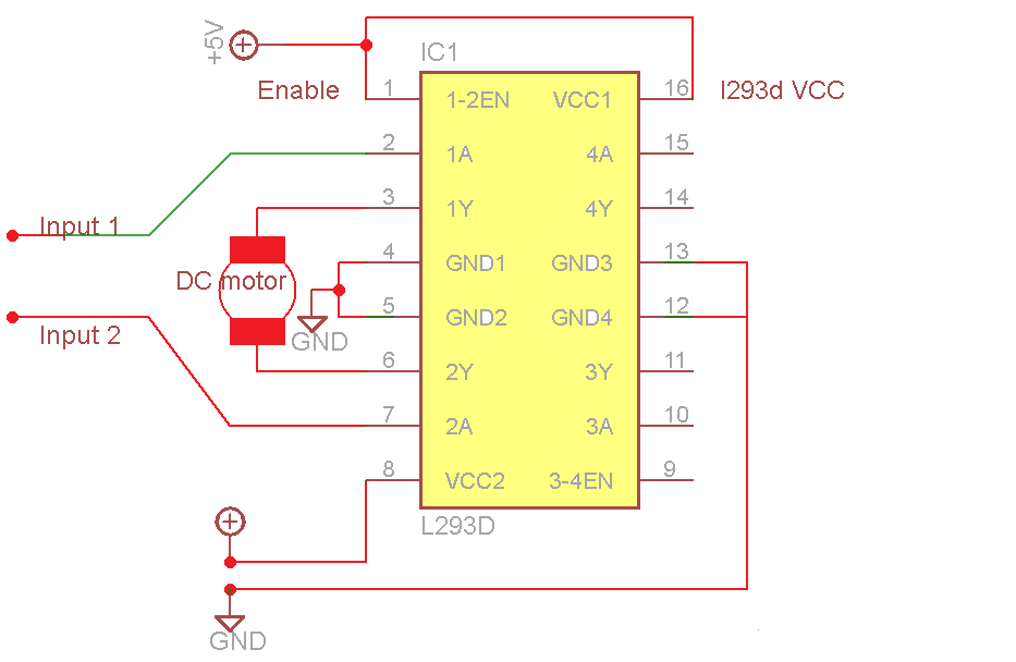
This is operated using L293d IC which is otherwise commonly known as the 'motor driver' IC. This IC is conected to the 12v supply. It takes inputs from the Arduino i.e. 5v input, and outputs 12v to its output pins (to which the actuator is connected). So, when the password is correct, pin 11 is set high and pin 12 is set low. Pins 11 and 12 are connected to the inputs of the l293d. Hence, the actuator is pulled inside and the door opens. shown in video 3.
Code
- code 1
- code 2
code 1Arduino
Scanningint rows=4;
int columns=4;
char readkey(void);
char nfunc(void);
#define c3 9
#define c2 8
#define c1 7
#define c0 6
#define r3 5
#define r2 4
#define r1 3
#define r0 2
void setup() {
Serial.begin(9600);
pinMode(c0,INPUT_PULLUP);
pinMode(c1,INPUT_PULLUP);
pinMode(c2,INPUT_PULLUP);
pinMode(c3,INPUT_PULLUP);
pinMode(r0,OUTPUT);
pinMode(r1,OUTPUT);
pinMode(r2,OUTPUT);
pinMode(r3,OUTPUT);
pinMode(11,OUTPUT);
pinMode(12,OUTPUT);
}
char readkey(void)
{digitalWrite(r0,LOW);
digitalWrite(r1,HIGH);
digitalWrite(r2,HIGH);
digitalWrite(r3,HIGH);
if(digitalRead(c0)==LOW){delay(500);
return '1';}
else if(digitalRead(c1)==LOW){delay(500);
return '2';}
else if(digitalRead(c2)==LOW){delay(500);
return '3';}
else if(digitalRead(c3)==LOW){delay(500);
return 'A';}
digitalWrite(r0,HIGH);
digitalWrite(r1,LOW);
digitalWrite(r2,HIGH);
digitalWrite(r3,HIGH);
if(digitalRead(c0)==LOW){delay(500);
return '4';}
else if(digitalRead(c1)==LOW){delay(500);
return '5';}
else if(digitalRead(c2)==LOW){delay(500);
return '6';}
else if(digitalRead(c3)==LOW){delay(500);
return 'B';}
digitalWrite(r0,HIGH);
digitalWrite(r1,HIGH);
digitalWrite(r2,LOW);
digitalWrite(r3,HIGH);
if(digitalRead(c0)==LOW){delay(500);
return '7';}
else if(digitalRead(c1)==LOW){delay(500);
return '8';}
else if (digitalRead(c2)==LOW){delay(500);
return '9';}
else if(digitalRead(c3)==LOW){delay(500);
return 'C';}
digitalWrite(r0,HIGH);
digitalWrite(r1,HIGH);
digitalWrite(r2,HIGH);
digitalWrite(r3,LOW);
if(digitalRead(c0)==LOW){delay(500);
return '*';}
else if(digitalRead(c1)==LOW){delay(500);
return '0';}
else if(digitalRead(c2)==LOW){delay(500);
return '#';}
else if(digitalRead(c3)==LOW){delay(500);
return 'D';}
return 'o';
}
char nfunc(void)
{
char key='o';
while(key=='o')
key=readkey();
return key;
}
void loop()
{
char key1= nfunc();
if(key1){
Serial.print(key1);
}
}
code 2Arduino
passwordint rows=4;
int columns=4;
int count=0;
char readkey(void);
char nfunc(void);
#define c3 9
#define c2 8
#define c1 7
#define c0 6
#define r3 5
#define r2 4
#define r1 3
#define r0 2
char password[5]="1234";
char typed[5];
void setup() {
Serial.begin(9600);
pinMode(c0,INPUT_PULLUP);
pinMode(c1,INPUT_PULLUP);
pinMode(c2,INPUT_PULLUP);
pinMode(c3,INPUT_PULLUP);
pinMode(r0,OUTPUT);
pinMode(r1,OUTPUT);
pinMode(r2,OUTPUT);
pinMode(r3,OUTPUT);
pinMode(11,OUTPUT);
pinMode(12,OUTPUT);
}
char readkey(void)
{digitalWrite(r0,LOW);
digitalWrite(r1,HIGH);
digitalWrite(r2,HIGH);
digitalWrite(r3,HIGH);
if(digitalRead(c0)==LOW){delay(500);
return '1';}
else if(digitalRead(c1)==LOW){delay(500);
return '2';}
else if(digitalRead(c2)==LOW){delay(500);
return '3';}
else if(digitalRead(c3)==LOW){delay(500);
return 'A';}
digitalWrite(r0,HIGH);
digitalWrite(r1,LOW);
digitalWrite(r2,HIGH);
digitalWrite(r3,HIGH);
if(digitalRead(c0)==LOW){delay(500);
return '4';}
else if(digitalRead(c1)==LOW){delay(500);
return '5';}
else if(digitalRead(c2)==LOW){delay(500);
return '6';}
else if(digitalRead(c3)==LOW){delay(500);
return 'B';}
digitalWrite(r0,HIGH);
digitalWrite(r1,HIGH);
digitalWrite(r2,LOW);
digitalWrite(r3,HIGH);
if(digitalRead(c0)==LOW){delay(500);
return '7';}
else if(digitalRead(c1)==LOW){delay(500);
return '8';}
else if (digitalRead(c2)==LOW){delay(500);
return '9';}
else if(digitalRead(c3)==LOW){delay(500);
return 'C';}
digitalWrite(r0,HIGH);
digitalWrite(r1,HIGH);
digitalWrite(r2,HIGH);
digitalWrite(r3,LOW);
if(digitalRead(c0)==LOW){delay(500);
return '*';}
else if(digitalRead(c1)==LOW){delay(500);
return '0';}
else if(digitalRead(c2)==LOW){delay(500);
return '#';}
else if(digitalRead(c3)==LOW){delay(500);
return 'D';}
return 'o';
}
char nfunc(void)
{
char key='o';
while(key=='o')
key=readkey();
return key;
}
void loop()
{
char key1= nfunc();
if(key1){
typed[count]=key1;
count++;
Serial.print(key1);
}
if(count==4){
if(strcmp(typed,password)==0)
{
Serial.println(" correct");
digitalWrite(11,HIGH);
digitalWrite(12,LOW);
delay(250);
digitalWrite(11,LOW);
}
else{
Serial.println(" intruder");
}
count=0;
}}
Schematics
 Connect actuator where the motor is connected.
Connect pin 8 to 12v
 pressed key displayed on the screenVID_20160924_195032.mp4led glows when the password is correctVID_20160924_200016.mp4The actuator is pulled outside in normal case (i.e. the door is locked).
When the password is correct , it is pulled inside and the door opensVID_20160924_201528.mp4
Manufacturing process
- Inside Bank Vaults: History, Design, and Future of Security
- Revolving Doors: Design, History, and Energy‑Saving Benefits
- The Evolution and Manufacturing of Modern Pin‑Tumbler Locks
- Combination Lock: Design, Manufacturing, and Historical Evolution
- Build an Arduino‑Powered Automatic Door with Ultrasonic Sensor
- Smart Keyless Door Lock – Arduino & Android Bluetooth‑Controlled Password System
- WiFi‑Enabled Smart Door Lock with Arduino & ESP8266 – Unlock via Phone
- Secure Your PC with an RFID‑Enabled Door Lock – Arduino Relay Project
- Arduino Keypad Door Lock with User-Defined Code
- Build an Arduino RFID Door Lock – Master RFID Technology with a Step‑by‑Step Guide