


Optimizing Fluid Drive Vibration in Boiler Feed Pumps: A Case Study
A boiler feed pump (BFP) powered by a fluid drive linked to the main steam turbine was plagued by excessive vibration, causing frequent bearing replacements. The plant relied on this single BFP for power generation, operating the fluid drive output shaft between 2,000 rpm and 3,500 rpm. Mechanical Solutions Inc. (MSI) conducted comprehensive tests that enabled the plant to adjust operations safely until a permanent solution could be implemented during a scheduled outage.
MSI’s field work combined impact modal testing with operating forced‑response experiments. Data were collected from roughly 125 points on the fluid drive, pump, front standard, and foundation. Impact modal tests identified natural frequencies and mode shapes during normal plant operation, while forced‑response data produced the operating deflection shape (ODS) of the pump and drive assembly (see Figure 1). The ODS reveals each component’s amplitude and phase at a given frequency, providing clear insight into the source and severity of vibration. MSI also employed shaft‑rider sticks to probe for torsional natural frequencies within the machinery train.
The tests pinpointed 60 Hz as the dominant vibration frequency, primarily affecting the fluid drive’s input end and the front standard, with a peak at 2,500 rpm (42 Hz). Notably, the output shaft experienced higher 60 Hz vibration than at 42 Hz. MSI concluded that the 60 Hz vibration stemmed mainly from a torsional critical speed of the rotor system that “tuned in” to 60 Hz, influenced by the fluid drive’s oil level. The torsional stiffness of the drive controlled the output speed, indirectly linking vibration to shaft speed. Additionally, a structural natural frequency of the fluid‑drive bearing pedestals at ~64 Hz was identified via ODS and modal testing. The combined rotor/structural vibrations severely degraded the foundation beneath the drive, with the ODS animation showing the sole plates detaching from the concrete, amplifying system shaking (Figure 1).
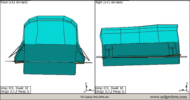
Figure 1. Freeze‑frame from an exaggerated‑motion animation of the modal “bump” test during pump operation. Notice the relative motion of the fluid drive base and sole plates to the foundation, which are no longer tightly connected.
Because the plant had to stay online, a long‑term foundation repair was not immediately feasible. Using MSI’s findings, the plant implemented a strategy to avoid operating the fluid drive at 2,500 rpm, thereby limiting rapid bearing wear and front‑standard deterioration. Permanent remedies—including foundation reinforcement and modifications to the coupling and other shaft components to shift the torsional critical speed—were scheduled for a future outage.
About the authors: William Marscher, President & Technical Director, and Eric Olson, Director of Marketing, Mechanical Solutions Inc. (MSI) – a consulting and R&D firm in Whippany, N.J. Learn more at www.mechsol.com or call 973‑326‑9920.
Equipment Maintenance and Repair
- Choosing the Optimal Drive System: Chain, V‑Belt, or Synchronous Belt
- Why Mastering Machine Troubleshooting is Critical for Modern Manufacturers
- Materials Used in Boiler Tubes: Choosing the Right Steel, Stainless, Copper and More
- Mastering Fluid Pump Systems: 3 Key Insights on Pressure-Flow Dynamics
- Professional Servo Drive Repair: Restoring Burnt Hypertherm Drives Without Schematics
- Essential Roles & Key Traits of Hydraulic Fluid for Optimal System Performance
- Hydraulic Contamination: Why Clean Fluid Is Crucial for Performance & Cost Savings
- Understanding DC Submersible Pumps: Features, Applications, and Benefits
- Centrifugal Pumps Explained: Key Features, Applications & Benefits
- Boost Production & Safety: Machine‑Tending Robots