


Accelerate Industrial Automation: Optimizing RS‑485 Fieldbus for Speed, Reach, and EMC
Industry leaders such as PROCENTEC report a steady rise in RS‑485‑based fieldbus deployments, notably PROFIBUS® and the rapidly expanding PROFINET Industrial Ethernet. In 2018, 61 million PROFIBUS nodes were installed worldwide, with process‑automation (PA) nodes growing 7 % year over year. The PROFINET install base reached 26 million nodes, and 5.1 million devices were added in 2018 alone.1
As Industry 4.0 drives the adoption of smart, connected factories, optimizing fieldbus technologies becomes essential for reliable, high‑performance systems. Achieving this requires a careful balance between electromagnetic compatibility (EMC) robustness and dependable data transmission.
Unreliable data can degrade overall system performance. In motion‑control applications, fieldbus is typically used for closed‑loop position control of single‑ or multi‑axis motors. High data rates and long cable runs—illustrated in Figure 1—are common. If position control is unreliable, machine throughput drops and factory productivity suffers. In wireless infrastructure, fieldbus often handles tilt/position control of antennas, where accurate data transmission is critical. Both scenarios demand different EMC protection levels, as shown in Figure 1. Motion‑control environments are electrically noisy, leading to data errors, while wireless setups must guard against indirect lightning strikes in exposed settings.
Meeting these demanding applications requires a thorough evaluation of RS‑485 transceiver timing over cables and EMC characteristics. This article presents key timing concepts, performance indicators such as clock and data distribution and cable drive capability, and demonstrates the benefits of next‑generation RS‑485 transceivers in industrial settings.
Timing Performance
When transmitting high‑rate data over long cables, timing metrics like jitter and skew—terms often associated with low‑voltage differential signaling (LVDS)—become critical for RS‑485. Both the transceiver and cable contribute to jitter and skew, and each must be assessed.
click for larger image
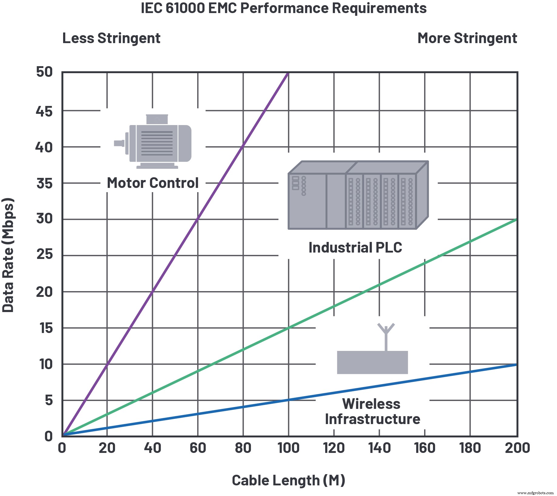
Figure 1. EMC, data rate, and cable length for RS‑485. (Source: Analog Devices)
Jitter and Skew
Jitter is the time‑interval error between the expected and actual arrival of a signal transition. Within a communication link, jitter originates from random sources—such as thermal noise and broadband shot noise—which follow a Gaussian distribution, and deterministic sources—such as duty‑cycle distortion, crosstalk, periodic external noise, or intersymbol interference (ISI). In RS‑485 systems, where data rates stay below 100 MHz, deterministic jitter dominates.
The peak‑to‑peak jitter value is a practical metric for total deterministic jitter. It can be visualized in the time domain by overlaying many signal transitions on the same display, forming an eye diagram. An oscilloscope’s infinite‑persistence mode or built‑in jitter‑decomposition software accomplishes this, as shown in Figure 2.2
click for larger image
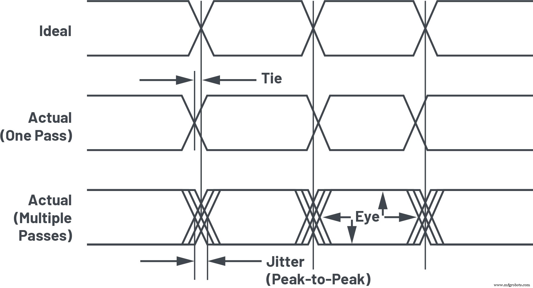
Figure 2. Time‑interval error, jitter, and eye. (Source: Analog Devices)
The width of the overlayed transitions represents peak‑to‑peak jitter; the open area is the eye. A wider eye provides the receiving node a larger sampling window, reducing the risk of bit errors. Deterministic jitter from the driver, receiver, and cable chiefly determines eye width.
click for larger image
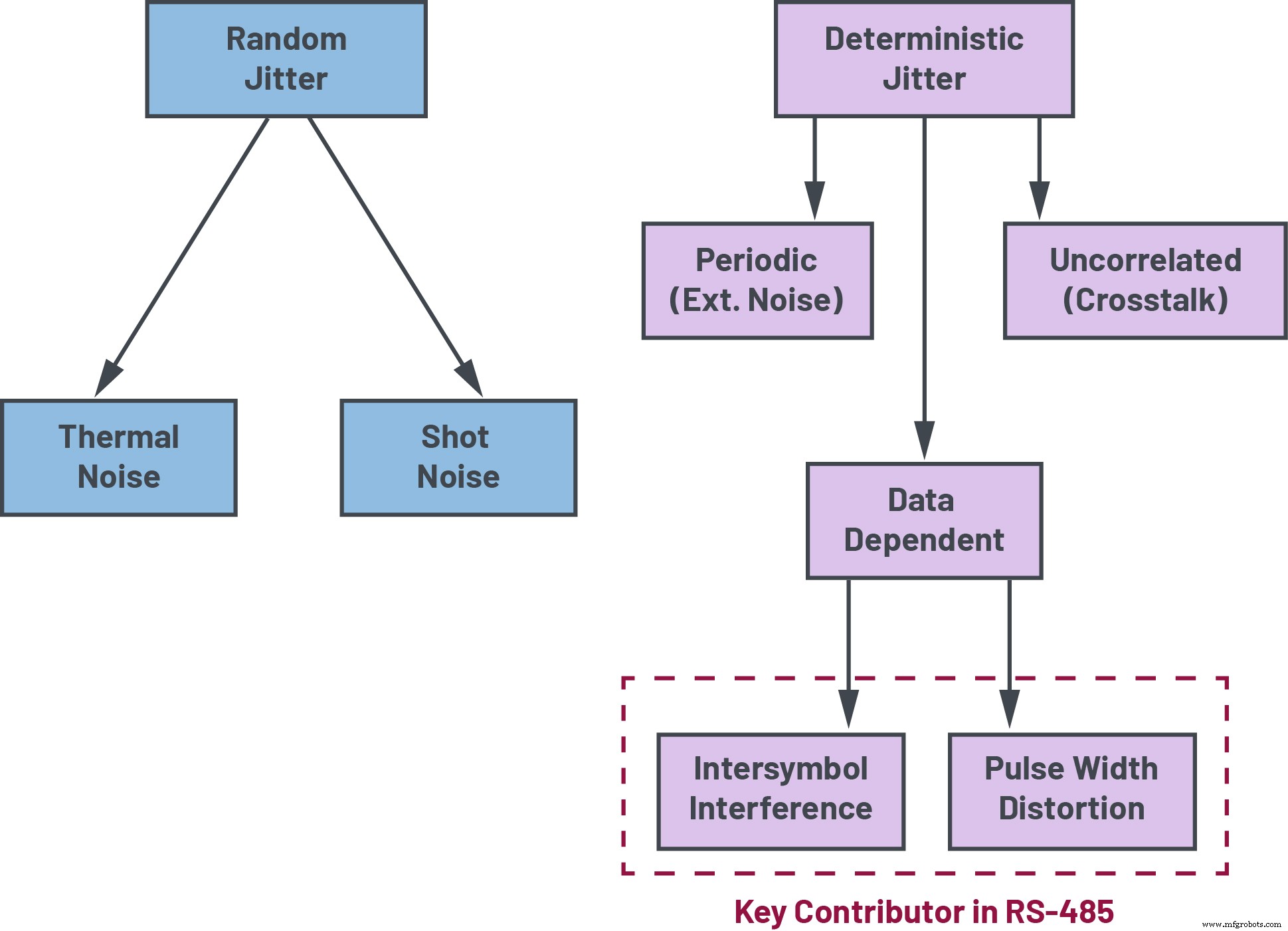
Figure 3. Key contributors to jitter in RS‑485 communication networks. (Source: Analog Devices)
Two critical contributors in RS‑485 systems are transceiver pulse skew and intersymbol interference (ISI). Pulse skew—also called pulse‑width distortion or duty‑cycle distortion—is the propagation‑delay difference between rising and falling edges. In differential links, this creates an asymmetric crossover point and mismatched durations for transmitted 0s and 1s, distorting the clock or data waveform. ISI occurs when a signal edge’s arrival is influenced by preceding data, especially over long cables where the cable’s RC time constant leaves the load capacitance partially charged by the end of a bit period. ISI is also exacerbated by impedance mismatches, line stubs, or improper termination. Transceivers with high output drive strength mitigate ISI by charging the cable capacitance more quickly.
The acceptable peak‑to‑peak jitter is application‑specific, but 10 % is a common benchmark for combining RS‑485 transceiver and cable performance. Excessive jitter or skew hampers the receiver’s sampling capability, raising communication‑error rates. In well‑terminated networks, selecting a transceiver that minimizes pulse skew and ISI yields a more reliable, error‑free link.
RS‑485 Transceiver Design and Cable Effects
The TIA‑485‑A/EIA‑485‑A standard3 defines electrical characteristics such as differential output voltage (VOD), short‑circuit behavior, common‑mode loading, and input thresholds. However, it does not specify timing metrics like jitter or skew; these are left to vendors’ datasheets and product specifications.
Complementary standards, such as TIA‑568‑B.2/EIA‑568‑B.2 for twisted‑pair cabling4, address cable‑induced effects on RS‑485 signals, including jitter, skew, and other timing limits. For example, Category 5e cable may tolerate up to 45 ns of skew per 100 m. Refer to “Enhanced RS‑485 Performance” for deeper insight into the impact of non‑ideal cabling on system performance.
While standards and datasheets provide useful guidance, meaningful timing characterization requires measuring a transceiver on a long cable.
click for larger image
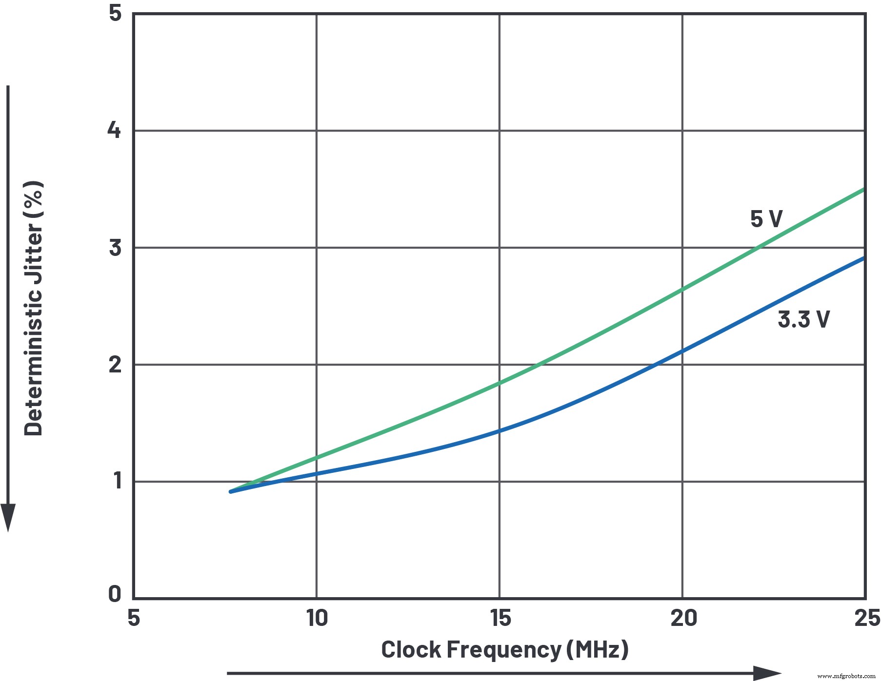
Figure 4. ADM3065E typical clock jitter performance. (Source: Analog Devices)
Communicating Faster and Further with RS‑485
Next‑generation RS‑485 transceivers deliver enhanced performance beyond the TIA‑485‑A/EIA‑485‑A specifications. For instance, the ADM3065E from Analog Devices offers ultralow transmitter and receiver skew, enabling reliable precision‑clock distribution—a feature vital for motor‑encoding standards like EnDat 2.25. Figures 4 and 5 show less than 5 % deterministic jitter across typical motor‑control cable lengths. The transceiver’s wide supply range (3.3 V to 5 V) ensures this performance for both low‑ and high‑voltage systems.
click for larger image
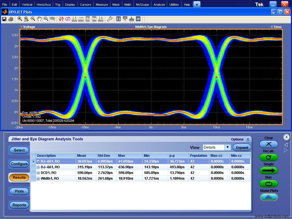
Figure 5. ADM3065E receiving eye diagram: 25 MHz clock distributed across 100 m cable. (Source: Analog Devices)
Enhanced timing also boosts data‑distribution reliability. Figure 6 demonstrates that with an advanced transceiver, the typical RS‑485 jitter ceiling of 10 % can be relaxed. The ADM3065E sustains >20 Mbps over 100 m while maintaining <10 % jitter at the receiver. This low jitter reduces sampling errors and delivers reliability previously unattainable with standard RS‑485 devices. If the receiving node tolerates up to 20 % jitter, data rates of up to 35 Mbps over 100 m are achievable.
click for larger image
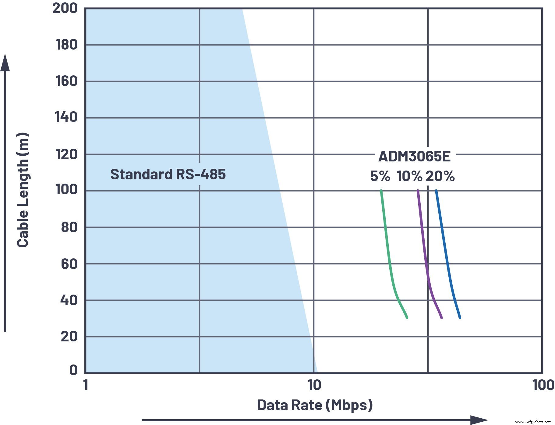
Figure 6. ADM3065E receiving data node superior jitter performance. (Source: Analog Devices)
For EnDat 2.2 encoder communication, data is transmitted in sync with falling clock edges. Figure 7 shows the start bit, error bits (F1, F2), and absolute position data. EnDat 2.2 requires a maximum of 10 % jitter and a 16 MHz clock over 20 m. The ADM3065E meets these constraints with only 5 % clock jitter, while also satisfying the data‑jitter requirement—something standard RS‑485 transceivers cannot guarantee.
click for larger image
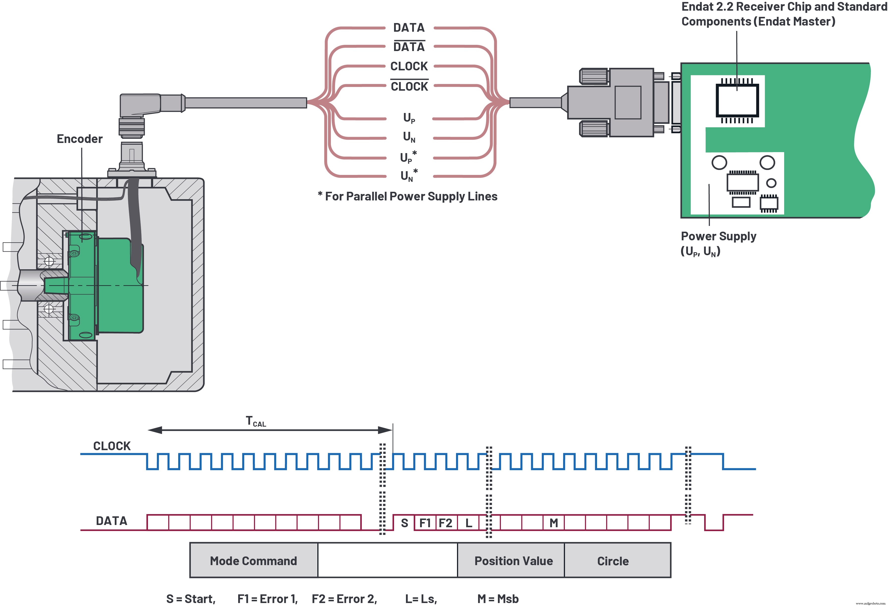
Figure 7. EnDat 2.2 physical layer and protocol with clock/data synchronization (adapted diagrams from EnDat 2.2). (Source: Analog Devices)
Better Reliability over Longer Cables
The TIA‑485‑A/EIA‑485‑A standard3 mandates a differential output voltage (VOD) of at least 1.5 V into a fully loaded network. This allows 1.3 V of DC attenuation over long cables, while receivers require at least 200 mV differential input. A transceiver designed to output ≥2.1 V at 5 V supply exceeds the standard’s VOD requirement, enhancing noise margin.
A fully loaded RS‑485 bus behaves like a 54 Ω differential load (two 120 Ω termination resistors plus 750 Ω representing 32 devices of 1 unit load, or 12 kΩ). The ADM3065E’s proprietary output architecture maximizes VOD while staying within common‑mode limits, exceeding the standard by >210 % at 3.3 V or >300 % at 5 V. This permits communication over longer distances, more remote nodes, and higher noise margins.
click for larger image
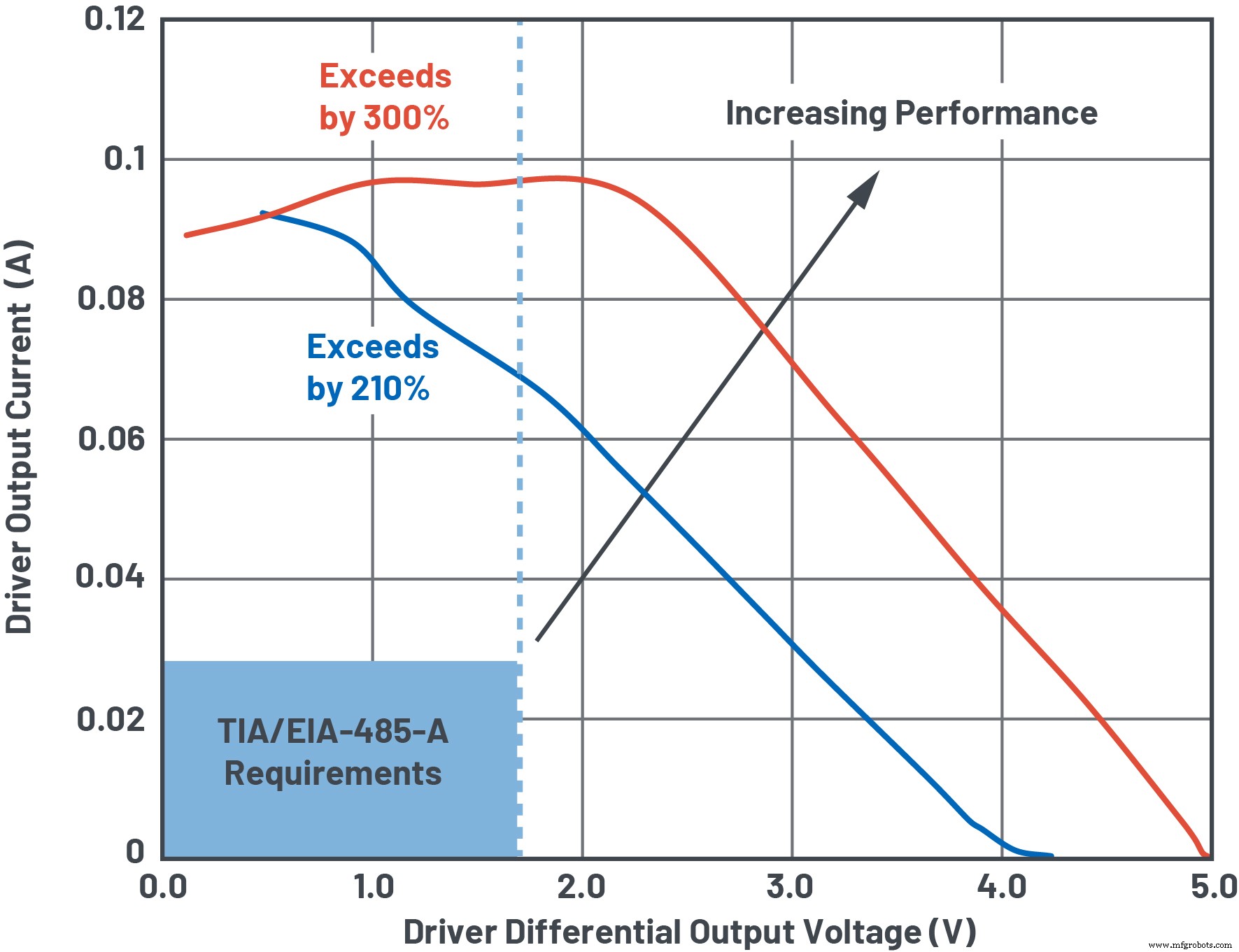
Figure 8. The ADM3065E exceeding the RS‑485 drive requirements across a wide supply range. (Source: Analog Devices)
Figure 9 illustrates performance over a 1 km AWG 24 cable. An enhanced transceiver yields 30 % greater noise margin than a standard RS‑485 device, or a 30 % increase in maximum cable length at low data rates—ideal for wireless infrastructure where cables can exceed several hundred meters.
click for larger image
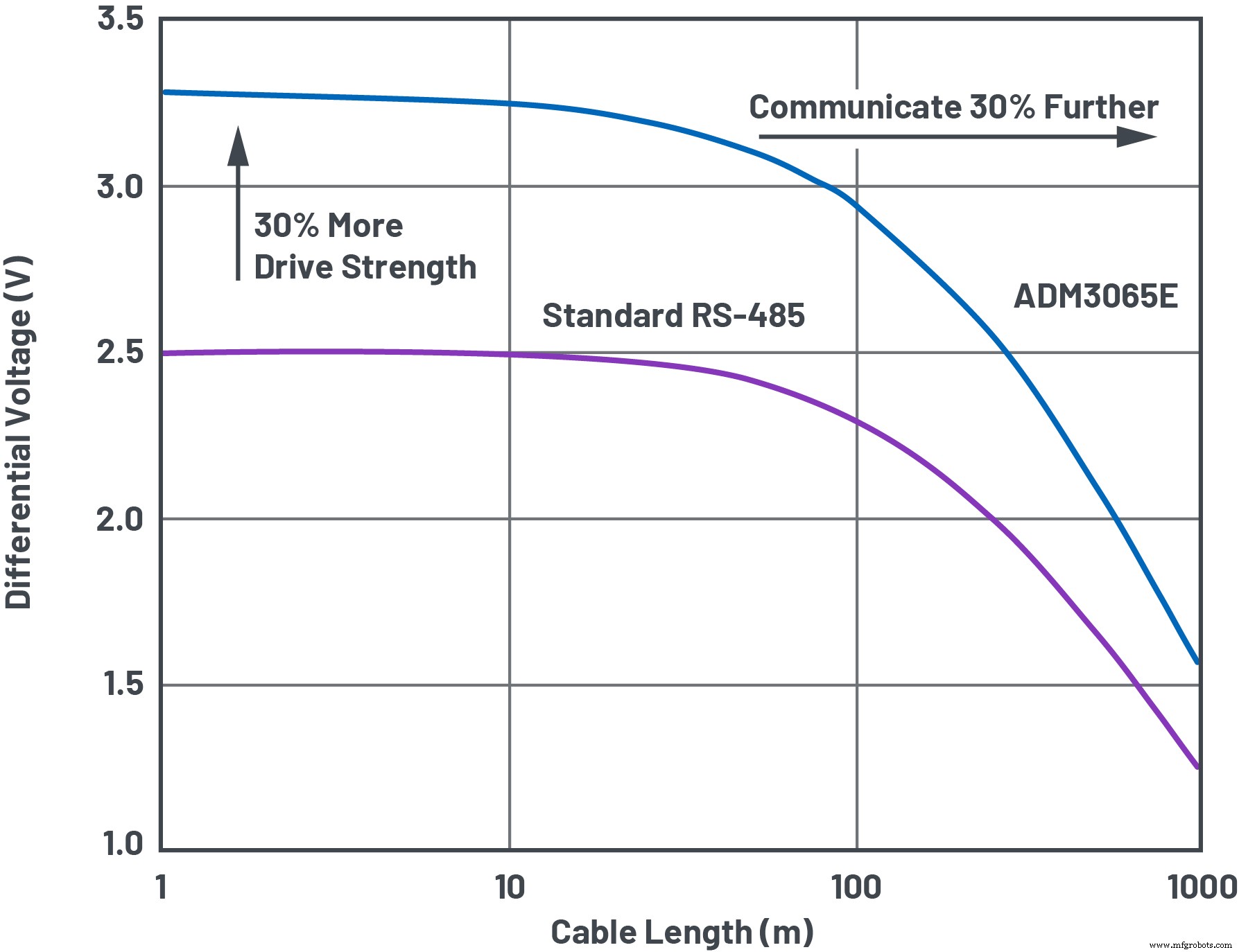
Figure 9. ADM3065E delivers a superior differential signal for ultralong distances. (Source: Analog Devices)
EMC Protection and Noise Immunity
RS‑485’s balanced, differential signaling inherently resists noise. Twisted‑pair cabling ensures induced currents flow in opposite directions, canceling electromagnetic fields. A stronger driver also improves the signal‑to‑noise ratio (SNR). Over long runs—hundreds of meters from ground to antenna—enhanced SNR and signal integrity secure accurate tilt/position control.
click for larger image
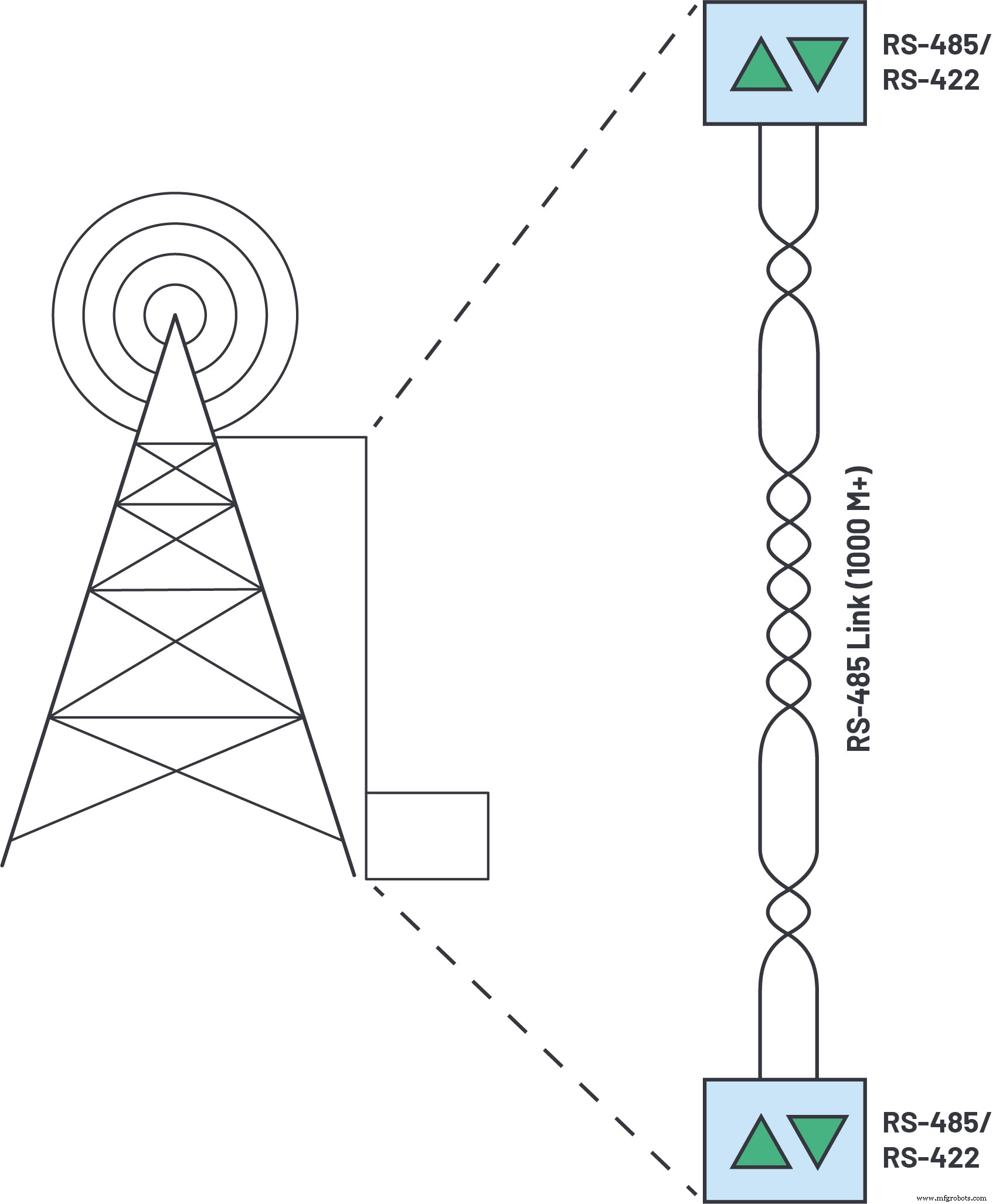
Figure 10. Wireless infrastructure cable lengths can extend over hundreds of meters. (Source: Analog Devices)
EMC protection is essential when transceivers interface with exposed connectors and cabling, as illustrated in Figure 1. ESD on RS‑485 connectors is a common hazard. IEC 61800‑3 requires a minimum ±4 kV contact/±8 kV air IEC 61000‑4‑2 ESD protection for adjustable‑speed drives. Enhanced transceivers like the ADM3065E exceed these limits with ±12 kV contact/±12 kV air protection.
click for larger image
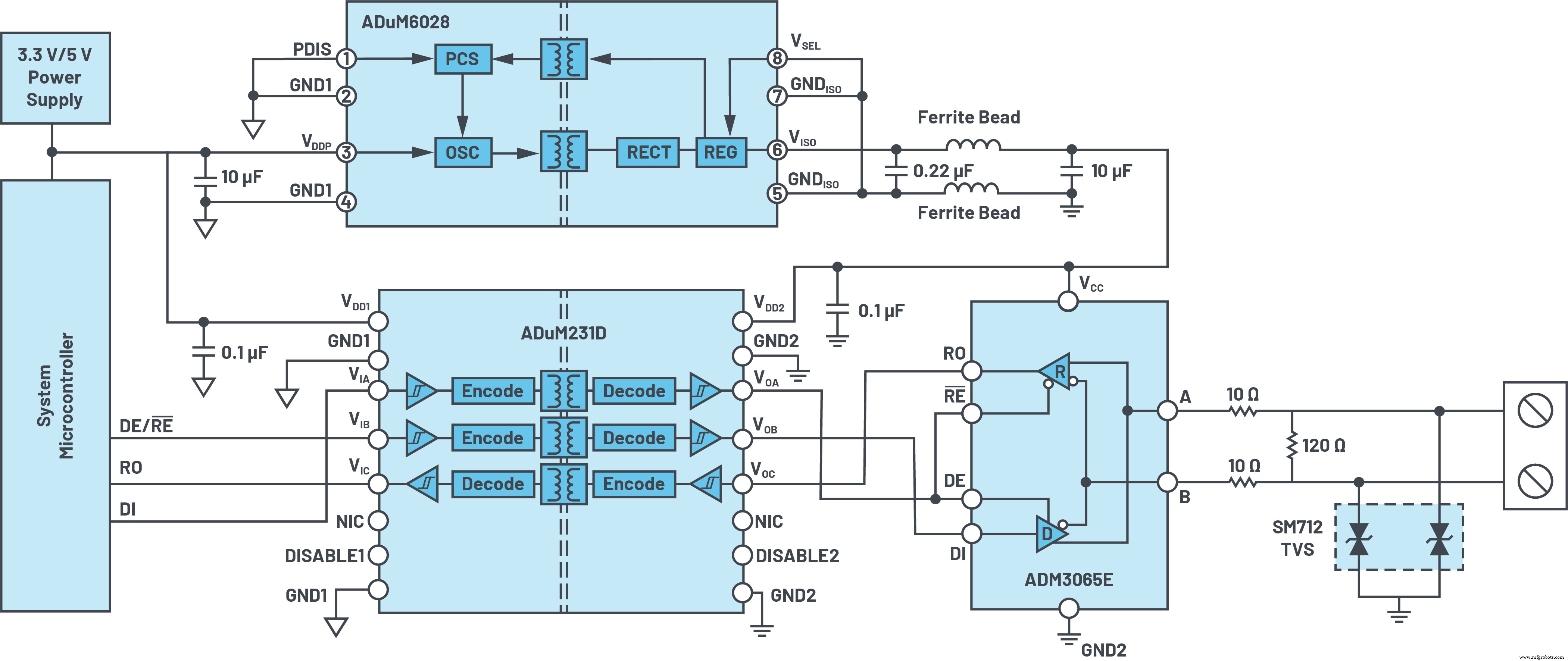
Figure 11. Complete 25 Mbps signal and power isolated RS‑485 solution with ESD, EFT, and surge protection. (Source: Analog Devices)
For wireless infrastructure, heightened EMC protection shields against lightning surges. Adding a SM712 TVS and two 10 Ω coordinating resistors to the transceiver inputs yields up to ±30 kV IEC 61000‑4‑2 ESD protection and ±1 kV IEC 61000‑4‑5 surge protection.
In harsh motor‑control, process‑automation, or wireless environments, galvanic isolation further boosts noise immunity. The ADM3065E can be paired with Analog Devices’ iCoupler® and isoPower® technologies. The ADuM231D provides three channels of 5 kV rms signal isolation with precise timing up to 25 Mbps, while the ADuM6028 offers isolated DC‑to‑DC conversion with 5 kV rms withstand. Two ferrite beads meet EMC standards such as EN 55022 Class B/CISPR 22, delivering a compact isolated solution in a 6 mm × 7.5 mm package.
Next‑generation RS‑485 transceivers surpass industry standards, enabling faster, longer, and more reliable communication. At the 10 % jitter level mandated by EnDat 2.2, systems can run 16 MHz clocks over 20 m—something standard RS‑485 cannot support. By exceeding the RS‑485 bus drive requirements by up to 300 %, designers achieve superior reliability and noise margin over extended cables. Adding iCoupler isolation, including the ADuM231D, and the compact ADuM6028 isolated power solution, further enhances immunity.
References
1 “PROFINET and PROFIBUS Node Count Tops 87 Million in 2018.” Profibus Group, May 2019.
2 Conal Watterson. “LVDS and M‑LVDS Circuit Implementation Guide.” Analog Devices, Inc., March 2013.
3 “TIA/EIA‑485‑A, Electrical Characteristics of Generators and Receivers for Use in Balanced Digital Multipoint Systems.” IHS Markit Inc., March 1998.
4 “TIA/EIA‑568‑B.2, Commercial Building Telecommunications Cabling Standard—Part 2: Balanced Twisted Pair Cabling Components.” Telecommunications Industry Association, May 2001.
5 “EnDat 2.2—Bidirectional Interface for Position Encoders.” Heidenhain, September 2017.
Embedded
- Securely Store and Manage Sensitive Data with Google Cloud Secret Manager
- DATA MODUL Launches Ultra‑Bright 21.5” & 31.5” Open‑Frame Monitors with EasyTouch for Outdoor & Indoor Use
- Microchip Introduces 24‑bit & 16‑bit Delta‑Sigma ADCs with 153.6 kSPS Data Rates
- Contrinex 2020: Cloud-Ready Sensors & Bluetooth Light Curtains for Safety
- Accelerate Design & Production with Formlabs and Fusion 360 Integration
- Enhancing Maintenance Planning & Scheduling Through Data Automation
- Accelerate Product Development: Faster Iteration & Prototyping with 3D Printing
- Java Variables and Data Types – A Comprehensive Guide with Examples
- PwC Insights: Harnessing AI & Big Data to Transform Manufacturing
- Leveraging Data and AI to Transform Manufacturing: Overcoming Industry Challenges