


Contactless Fluid‑Level Sensing with a Reflectometer Chip
Measuring fluid levels without drilling holes is possible by clamping an air‑dielectric transmission line to a tank’s exterior and detecting the change in RF impedance with a reflectometer chip. This guide walks through an empirical design example that demonstrates how a single‑chip reflectometer, such as Analog Devices’ ADL5920, can simplify the process.
Compared with conventional float‑based sensors, a reflectometer‑based system offers:
- Real‑time, high‑speed measurements
- Extensive digital post‑processing
- Contactless operation – no liquid contamination
- No moving parts, boosting reliability
- Minimal radiated RF – far‑field cancellation
- Leak‑free design – no penetrations in the tank wall
- Intrinsic safety – no electrical components inside the tank
Fluid‑Level Measurement Overview
The system block diagram in Figure 1 shows an RF source driving a balanced, 50‑Ω terminated air‑dielectric line with an inline reflectometer.
click for larger image
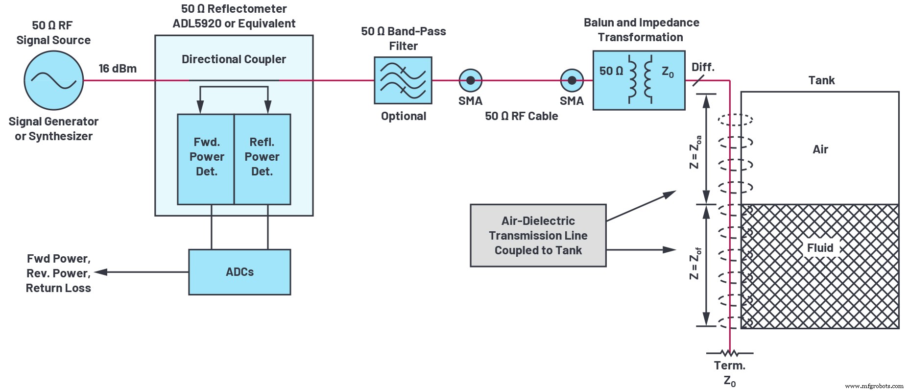
Figure 1. Fluid‑level measurement system block diagram. (Source: Analog Devices)
Principle of Operation
Air‑dielectric lines exhibit low loss and a well‑defined characteristic impedance (Z0). When a dielectric material—such as the tank wall or the fluid inside—approaches the line, the impedance, propagation velocity, and attenuation all shift. A reflectometer measures the resulting return loss, which can be correlated to fluid level. Key effects include:
- Lower characteristic impedance
- Reduced propagation velocity, increasing effective electrical length
- Higher attenuation
When the line is first attached to the tank, the near‑field dielectric of the tank wall slightly lowers the impedance to ZOA and increases electrical length (Trace 1 in Figure 2). As fluid fills the tank, the impedance drops further to ZOF, rotating the Smith chart trace clockwise (Trace 2 and Trace 3) and reducing return loss at the source end.
click for larger image
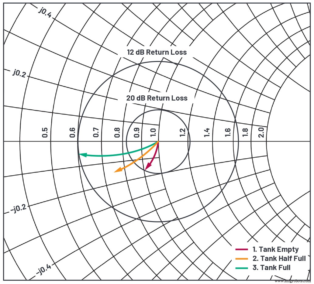
Figure 2. Smith chart representation of transmission line input impedance. Trace endpoints show how fluid level translates to return loss. (Source: Analog Devices)
To avoid ambiguity, the line’s electrical length should be ≤90°; otherwise, the return loss appears to fold back.
Balun Role
The balun drives the line with equal but opposite AC voltages, providing two main benefits:
- Suppresses stray RF coupling, enhancing EMI compliance
- Transforms higher impedance, widening conductor spacing and deepening the electric field for greater sensitivity
Band‑Pass Filter
When stray RF may couple into the line, a band‑pass filter (see Figure 1) is recommended. It should have low insertion loss and return loss better than ~30 dB.
Basic Design Procedure
- Choose an operating frequency so the line length is 0.1–0.25 of the free‑space wavelength. Lower frequencies yield better linearity; higher frequencies increase return‑loss range but risk fold‑back. ISM band selections are available at Wikipedia: ISM band.
- Design or select a balun for the chosen frequency. Verify ~30 dB return loss on a single‑ended port with the resistive termination attached.
- Use an arbitrary transmission line calculator (ATLC) (ATLC) to compute conductor width and spacing for the target Z0.
click for larger image
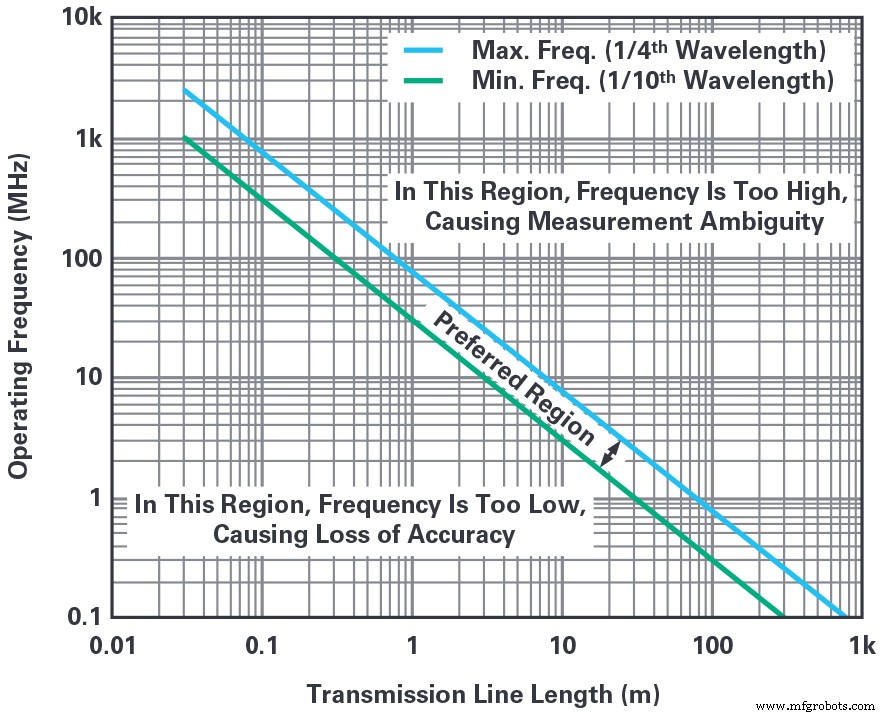
Figure 3. Recommended operating frequency vs. transmission line length. (Source: Analog Devices)
A Simple Design Example
We built a level sensor for an automotive windshield washer tank (~15 cm high). The design steps were:
- Target frequency ~300 MHz (see Figure 3).
- Designed an LC balun with a slight impedance step‑up to enhance sensitivity; verified ~30 dB return loss.
- Fabricated a parallel transmission line matching the balun’s Z0; measured ~25 dB return loss with the line in‑circuit.
click for larger image
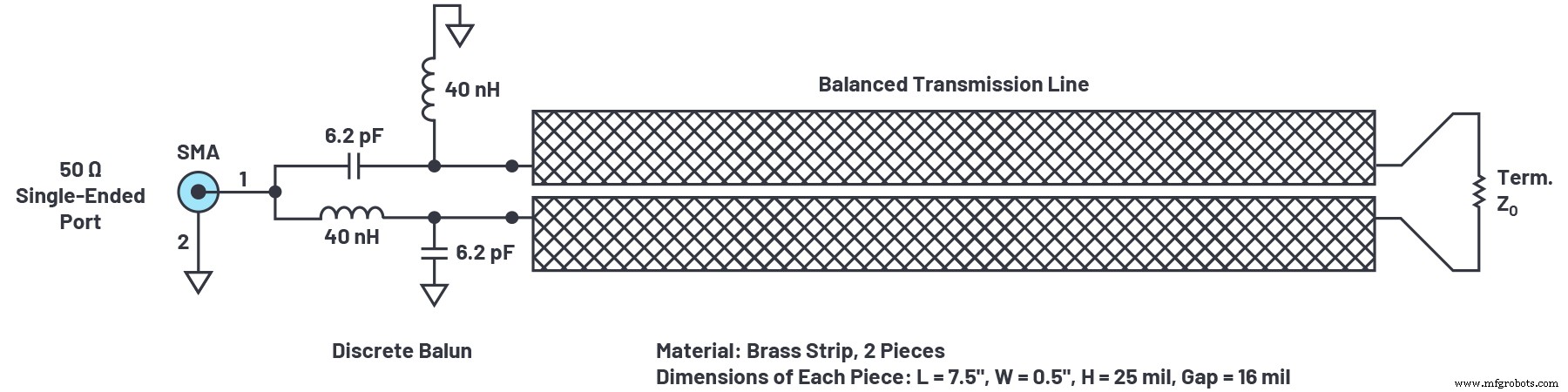
Figure 4. Balun and transmission line used for fluid level sensing example. (Source: Analog Devices)
click for larger image
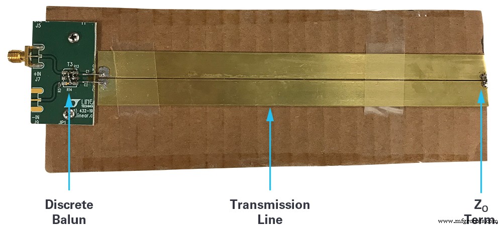
Figure 5. Discrete balun and terminated transmission line before affixing to the tank. (Source: Analog Devices)
After attaching the line to the tank (Figure 6), a slight drop in return loss was observed due to the tank wall acting as an extra dielectric.
click for larger image
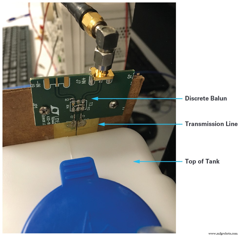
Figure 6. Transmission line affixed to the tank side. (Source: Analog Devices)
Example Test Results
The full test setup is shown in Figure 7. A DC2847A evaluation kit reads forward and reflected power (dBm) from the ADL5920, automatically computing return loss and displaying the results graphically.
click for larger image
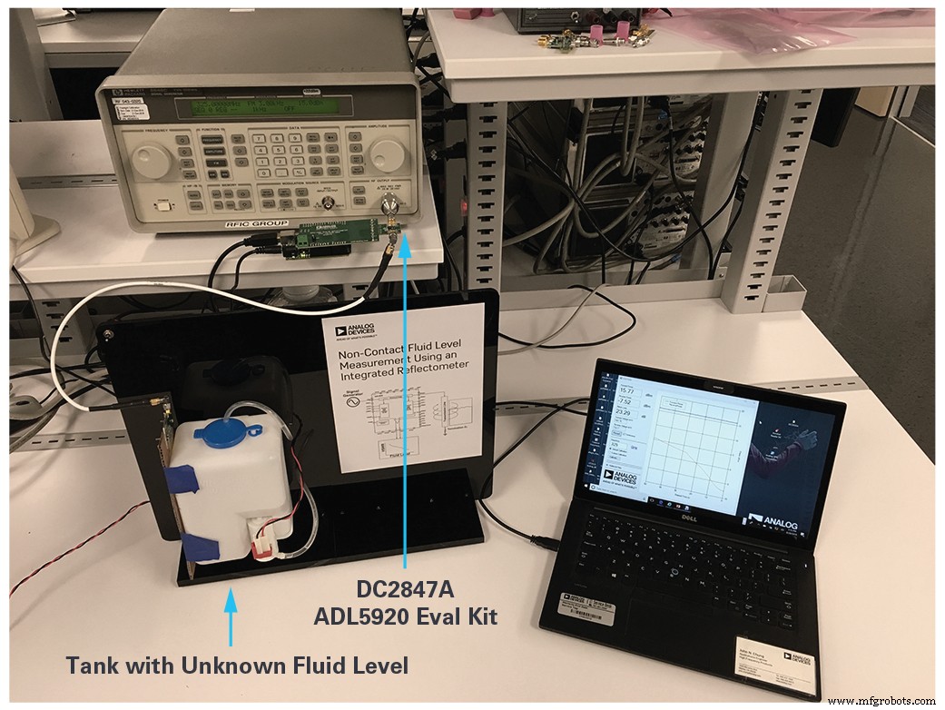
Figure 7. Complete test setup for the design example. (Source: Analog Devices)
During pumping, the tank level rose linearly, and reflected power fell accordingly. At ~33 s, a slope change appeared due to the tank’s tapered bottom—an effect that can be corrected in firmware.
click for larger image
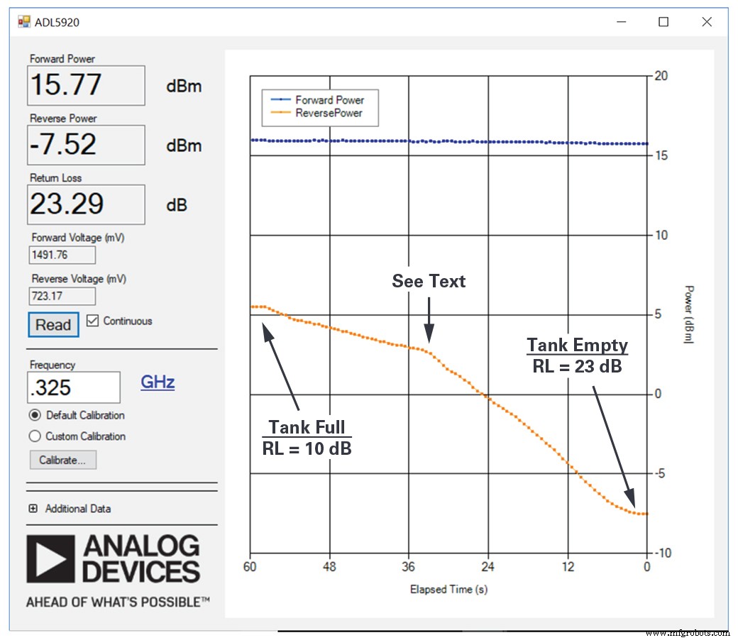
Figure 8. Test results vs. fluid level. Linear and monotonic, except for tank‑design induced nonlinearity. (Source: Analog Devices)
Calibration
Two calibration steps improve accuracy:
- Device calibration—corrects for slope and intercept variations in the ADL5920. The DC2847A kit performs this automatically.
- Fluid‑level calibration—maps return loss to level, accounting for manufacturing tolerances, tank wall thickness, and dielectric changes with temperature. Use at least three calibration points if nonlinearity is present.
Calibration constants are stored in non‑volatile memory, either within an embedded processor or on a dedicated EEPROM.
Measurement Limitations
The reflectometer’s directivity determines how well it separates incident and reflected waves. For the ADL5920, directivity is ~20 dB at 1 GHz, improving to ~43 dB at 100 MHz or lower, making it suitable for tanks ≥30 mm tall.
Application Extensions
Potential extensions include:
- Low‑duty‑cycle operation for power savings
- Return‑loss correlation to viscosity or pH when level is constant
- High‑accuracy measurement at the top or bottom of the scale by tailoring the sensor geometry
- Metallic tanks may require submerged transmission lines
- Multiple RF power levels for self‑test against external interference
- Multi‑side transmission lines to compensate for tank tilt
- Short, high‑frequency lines for threshold detection
Conclusion
The ADL5920’s single‑chip reflectometer opens a new class of fluid‑level sensors that eliminate moving parts, reduce contamination risk, and provide high reliability for industrial and automotive applications such as oil and fuel monitoring.
Acknowledgements
Thanks to Michiel Kouwenhoven, James Wong, Bruce Nguyen, and John Chung for their guidance.
Embedded
- Finite-Length Transmission Lines: Impedance, Reflections, and Termination
- Understanding Long and Short Transmission Lines in Electrical Engineering
- Initializing FPGA Block RAM from Text Files Using VHDL’s TEXTIO Library
- Laser Alignment for Vertical Shaft Plumbness: Faster, More Accurate Measurements
- IBM Breaks New Ground with 7 nm FinFET Technology Using EUV Lithography
- Automating Facebook Login with Python and Selenium: A Step‑by‑Step Guide
- Accurate Frequency & Duty Cycle Measurement with Arduino UNO
- Precise Ultrasonic Distance Sensing with Arduino – Step‑by‑Step Guide
- Understanding PCB Transmission Lines: Design, Function, and Applications
- How a Powder Coating Line Enhances Efficiency, Durability, and Cost Savings