


Comparing Auto‑Addressing Schemes for Bluetooth Car Access Systems
Bluetooth Low Energy (BLE) car‑access systems typically feature a central module and multiple satellite nodes that communicate over a Controller Area Network (CAN) or Local Interconnect Network (LIN) bus. The satellites are strategically placed around the vehicle to extend the BLE range.
Designers aim to streamline satellite manufacturing by using a single PCB design and identical firmware across all nodes. This uniformity, however, necessitates an on‑board mechanism for the central module to assign unique CAN or LIN addresses to each satellite after installation.
Traditional wired approaches employ a dedicated LIN daisy‑chain to distribute CAN IDs during manufacturing. The LIN interface is then disabled for the vehicle’s lifetime. An alternative reduces bill‑of‑materials (BOM) costs by replacing the dedicated LIN bus with a minimal discrete circuit. A truly wireless option eliminates extra hardware entirely, leveraging the existing BLE infrastructure to perform the address assignment.
By removing the need for dedicated LIN hardware, the wireless method cuts wiring, BOM, and the overhead of stocking and assembling unnecessary components. This article first reviews wired auto‑addressing techniques before delving into the wireless approach.
Modern car‑access systems increasingly adopt BLE for phone‑as‑a‑key or digital‑key functions. These systems operate like passive‑entry, passive‑start setups but replace traditional key fobs with a driver’s smartphone. A typical configuration consists of one central module and six to twelve satellite modules, each capable of receiving BLE signals from the phone or key fob (Figure 1).
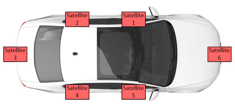
Figure 1. Example placement of BLE satellite modules throughout a vehicle.
For the phone‑as‑a‑key system to unlock, the central module must determine when the smartphone or key fob is within the vehicle’s unlocking zone. This is achieved by triangulating signals received by multiple satellite modules distributed across strategic locations such as passenger doors, rocker panels, trunks, and bumpers.
The central module communicates with the satellites via CAN or LIN. Using the data from each satellite, it triangulates the smartphone’s location and decides whether to grant entry. Figure 2 illustrates a CAN‑based communication topology.
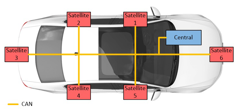
Figure 2. CAN bus as the primary communication network between the central module and satellites.
The CAN address of each satellite lets the central module identify the source of incoming data. Assigning a unique CAN ID or address to each satellite is essential for correct operation. Rather than hard‑coding a distinct PCB for every satellite, manufacturers prefer a single PCB design running the same firmware on all nodes. This approach reduces inventory complexity and enables installation of the same module in any vehicle location.
Since all satellites are identical and unaddressed at installation, a post‑installation auto‑addressing scheme is required.
Wired auto‑addressing: LIN daisy‑chain method
Currently, many OEMs use a separate LIN bus for one‑time CAN address assignment. The central module sends a CAN address over LIN to the first satellite; that node forwards the next address to the second satellite, and so on (Figure 3). Each module requires two LIN PHYs—one for transmission and one for reception—used only during auto‑addressing. With six to twelve satellites, a vehicle may need 14 to 26 LIN PHYs, inflating the BOM and complexity.
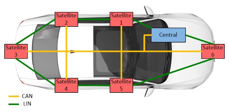
Figure 3. LIN daisy‑chain auto‑addressing architecture.
Wired auto‑addressing: Single‑wire method
Texas Instruments introduced a cost‑saving alternative that replaces the LIN PHYs with a MOSFET and a few resistors. In this scheme, all satellites ignore the CAN bus until a wake signal is received on the P_IN line (Figure 4). The central module initiates the process by pulsing P_IN1 through Q1. The first satellite receives the wake signal, begins listening to the CAN bus, and receives its CAN ID. After acknowledging receipt, it sends the wake signal to the next satellite, and the sequence repeats until every node is addressed.
click for larger image
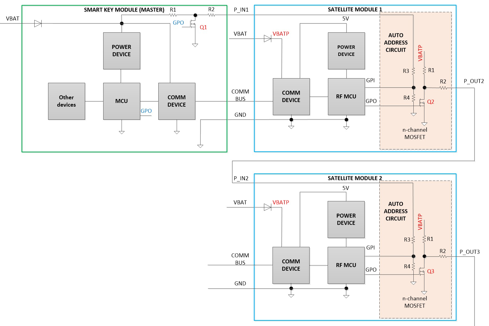 Figure 4. Single‑wire auto‑addressing replaces LIN PHYs with MOSFET and resistors.
Although this method reduces component count, it still requires a dedicated wiring connection between the central module and each satellite (Figure 5).
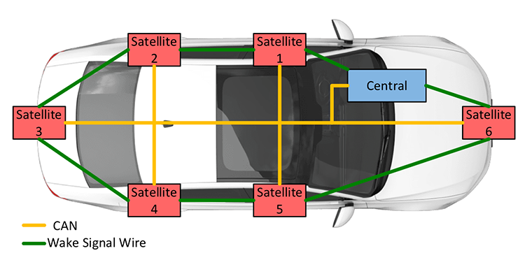
Figure 5. Wiring required for the single‑wire auto‑addressing architecture.
Wireless auto‑addressing/cable replacement
Another TI solution eliminates extra wiring entirely by using BLE localization. During manufacturing or module replacement, the central module assigns CAN addresses based on measured distances (derived from RSSI). Satellites closest to the central module receive the lowest CAN IDs, followed by progressively farther modules. The actual physical location is not needed; consistency in measured distances guarantees repeatable addressing.
For instance, if the measured distances satisfy d1 < d6 < d5 < d2 < d4 < d3, the central module can reliably assign addresses 1 through 6. If two satellites produce similar distances, an already‑addressed satellite can serve as a secondary reference to differentiate them (Figure 7).
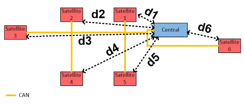
Figure 6. Distance relationships used for wireless auto‑addressing.
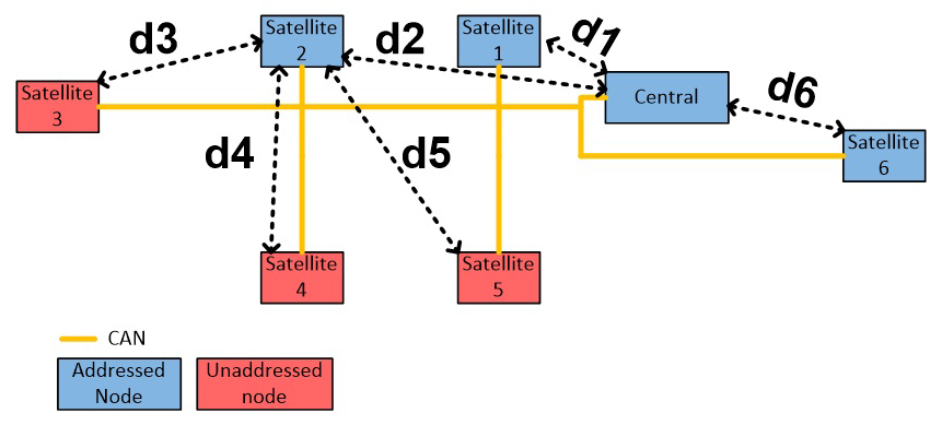
Figure 7. Using a previously addressed satellite to resolve distance ambiguities.
Implementation details
In line with the Generic Access Profile (GAP) of BLE, the central module is termed the “scanner” and the satellites the “advertisers.” The GAP layer manages device discovery, link establishment, and security. Two key states are:
- Advertiser: Broadcasts connectable advertising data, including a unique device address and optional name.
- Scanner: Scans for advertisements, sends scan requests, and initiates connections.
During auto‑addressing, each advertiser broadcasts with a random identifier to prevent duplication. The scanner repeatedly measures RSSI, averages the values, and selects the nearest advertiser. It then sends a scan request, transmits the auto‑address CAN message, and waits for acknowledgment. Upon acknowledgment, the advertiser stops advertising and proceeds to the next node. This cycle repeats until all satellites are addressed.
Results
Testing employed TI’s Bluetooth Low Energy + CAN satellite reference design and a 12‑ft harness with ~6‑ft spacing between connectors (Figure 9). The scanner used a 1‑s scan duration with a 250‑ms window/interval; advertisers advertised every 100 ms. Ten RSSI samples were taken per node, and the average was used to estimate distance.
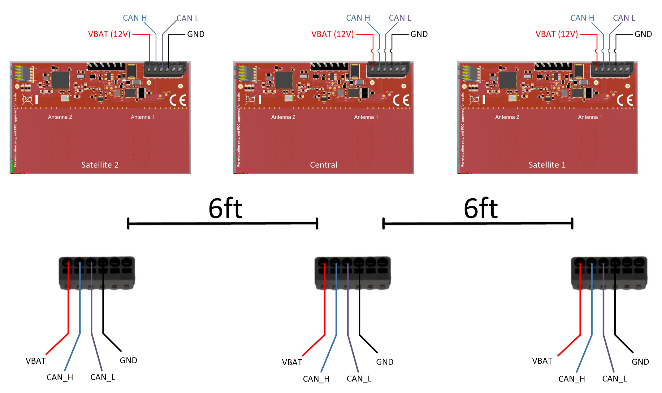
Figure 9. Hardware test setup using the TIDA‑020032 reference design.
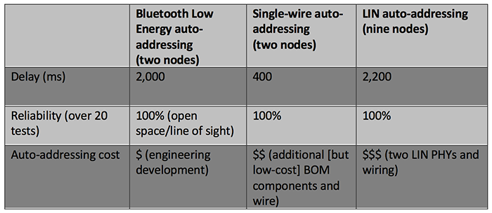
Table 1 summarizes the delay, reliability, and implementation cost of the three methods. The wireless approach incurs roughly five times longer addressing time compared to wired schemes, but offers the lowest BOM and eliminates wiring. Performance can be improved by refining BLE parameters and accounting for RF propagation variations.
Table 1. Comparison of auto‑addressing techniques
For detailed single‑wire test data, refer to TI’s car‑access Bluetooth Low Energy + CAN satellite module reference guide. When choosing an auto‑addressing strategy, consider cost, wiring complexity, and the need for post‑manufacturing flexibility.
* For additional details and test results on the single‑wire auto‑addressing method, consult the Texas Instruments car access Bluetooth Low Energy + CAN satellite module reference design guide.
References
- Bluetooth core specifications
- The Standard for Connection Sets New Standards in Safety, Bluetooth SIG
>> This article was originally published on our sister site, EDN.
Embedded
- The Evolution and Future of Satellite Dish Technology
- C# Constructors: Types, Examples, and Advanced Patterns
- Understanding C# Nested Classes: Definition, Usage, and Inheritance
- Bluetooth Mesh Design Choices: Module vs. Discrete Device
- NXP Launches UWB Chip to Turn Smartphones into Secure Digital Keys
- Ultra‑Small u‑blox BMD‑380 Bluetooth 5.0 Module with Built‑In Ceramic Antenna
- Renesas Licenses 3db Access Ultra‑Wideband Technology for Secure IoT Connectivity
- Compact OB1203 Biosensor Module Unites Heart Rate, Pulse Oximetry, and More for Wearables
- Dialog Launches Ultra‑Low‑Cost DA14531 SmartBond TINY BLE Module
- HS Flex Handling System Boosts Operator Efficiency and Storage in Hermle C42 Machining Center