


Establishing Baseline Performance for High‑Precision MEMS Accelerometers
In the first part of this series we explored the internal architecture of the 3‑axis ADXL355 MEMS accelerometer. This article explains how to collect a reliable starting dataset that will confirm the device’s noise floor and validate expectations for subsequent signal‑processing experiments.
Although the accelerometer’s analog output can be wired to any DAQ system, Analog Devices supplies a compact evaluation board – the EVAL‑ADXL35x – designed for quick integration into embedded prototypes. For this study the board was mounted on an SDP‑K1 microcontroller and programmed through the free, ARM‑based Mbed environment. The SDP‑K1 appears as an external drive when connected to a PC, allowing the user to flash the compiled binary simply by dragging it onto the drive.
Once the Mbed firmware was running, data were streamed via UART to a terminal and logged at 2 Hz. Although the ADXL355 can output data at much higher rates, this paper focuses on the low‑rate logging that is sufficient for establishing a baseline.
To secure a stable measurement surface, the sensor was clamped to a glass bench using a PanaVise articulated arm equipped with a suction‑cup mount. While the vise can introduce a small tipping risk, it is a cost‑effective method for rotating the sensor relative to gravity without moving the entire bench. The ADXL355 was positioned as shown in Figure 1 and a 60‑second data stream was captured for initial analysis.
click for full size image
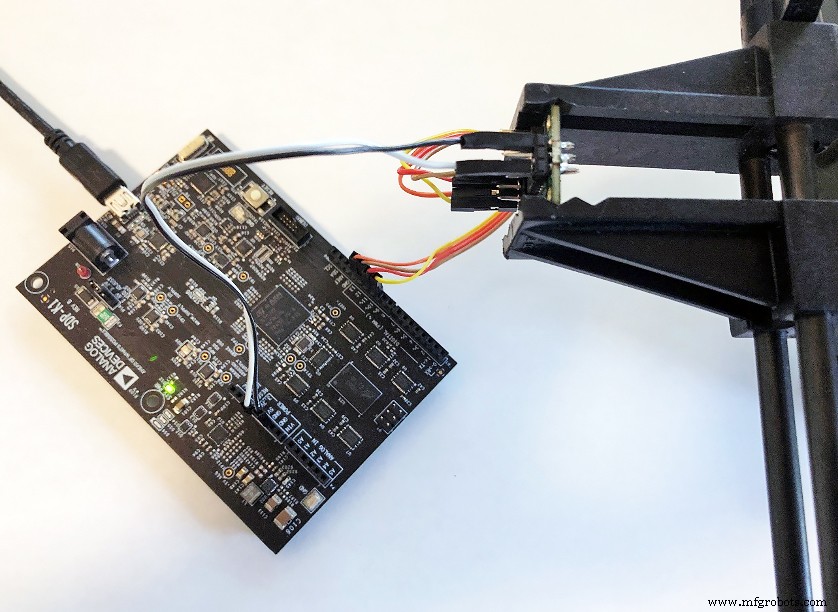
Figure 2. Test setup using an EVAL‑ADXL35x, SDP‑K1, and PanaVise mount. (Source: Analog Devices)
click for full size image
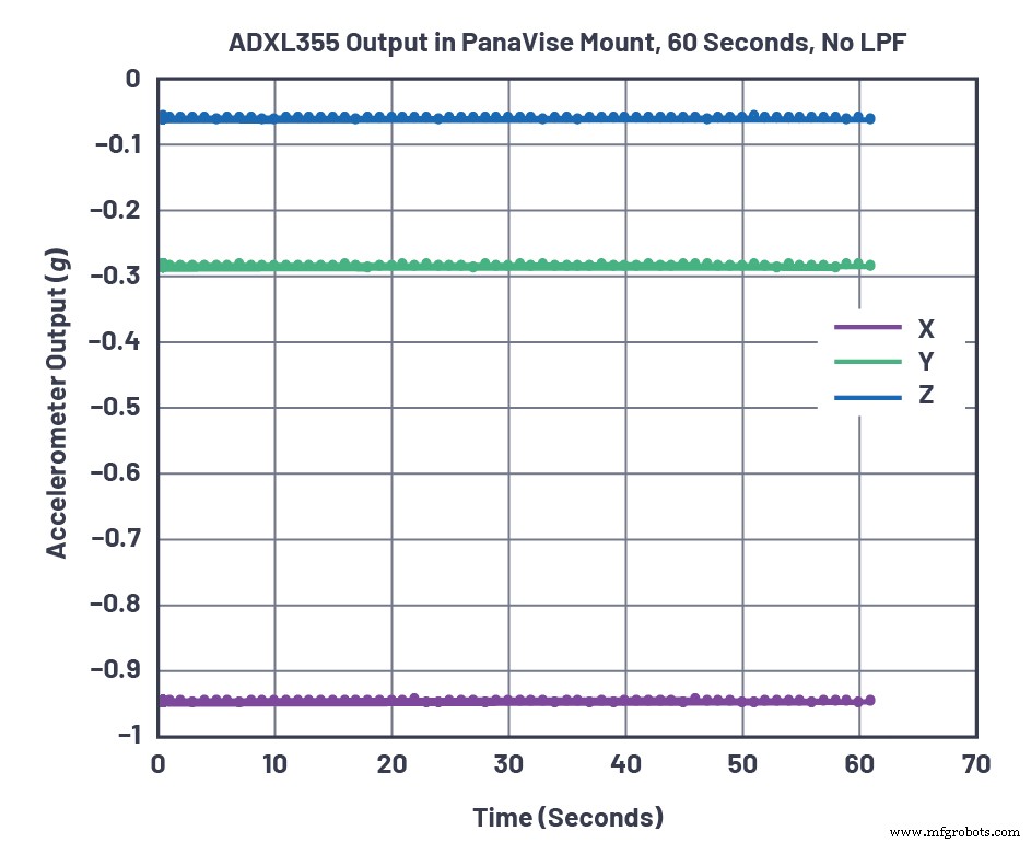
Figure 3. ADXL355 data with no low‑pass filter (register 0x28=0x00), taken over 1 minute. (Source: Analog Devices)
From the 120 samples, the standard deviation ranged from 800 µg to 1.1 m g. The ADXL355 datasheet lists a noise density of 25 µg/√Hz. With the default 1 kHz bandwidth (LPF enabled) this translates to 25 µg/√Hz × √1000 Hz ≈ 791 µg rms, assuming a brick‑wall filter. The measured values fall comfortably within this theoretical range, confirming the sensor’s noise performance.
Most precision applications do not require a 1 kHz bandwidth. By configuring the onboard digital low‑pass filter (LPF) to 4 Hz, the effective noise should reduce by a factor of √1000/√4 ≈ 16. The Mbed firmware adjustment is shown in Figure 4, and the resulting data in Figure 5. Table 1 summarizes the measured and theoretical noise for each axis with and without the LPF.
click for full size image

Figure 4. Mbed code for configuring a register. (Source: Analog Devices)
click for full size image
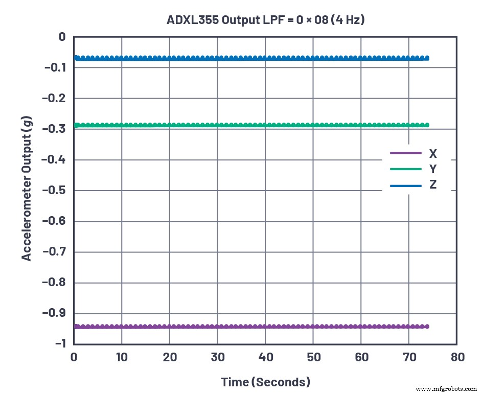
Figure 5. ADXL355 data with the LPF set to 4 Hz (register 0x28=0x08), taken over 1 minute. (Source: Analog Devices)
| X‑Axis | Y‑Axis | Z‑Axis | ||||
|---|---|---|---|---|---|---|
| Theoretical (µg) | Measured (µg) | Theoretical (µg) | Measured (µg) | Theoretical (µg) | Measured (µg) | |
| No Filter | 791 | 923 | 791 | 1139 | 791 | 805 |
| 4 Hz Filter | 50 | 58 | 50 | 185 | 50 | 63 |
Notice that the Y‑axis noise exceeded the theoretical prediction. A systematic investigation revealed that the lab’s laptop and other equipment fans introduced vibration predominantly in the Y‑direction. Rotating the sensor so that the X‑axis aligned with the vibration source shifted the excess noise to the X‑axis, confirming that the observed discrepancy stemmed from external mechanical disturbances rather than intrinsic sensor variance.
To evaluate the sensor’s response to rapid thermal disturbances, a Weller 6966C hot‑air gun was operated on the “cool” setting (≈ 40 °C rise). The ADXL355’s on‑board temperature sensor logged the ambient temperature while the gun delivered warm air to the ceramic package, which is hermetically sealed. Figure 6 demonstrates the pronounced 1.5 m g offset in the Z‑axis and the much smaller shifts in X and Y. When the gun was turned off, the Z‑axis returned to baseline almost instantaneously, as shown in Figure 7.
click for full size image
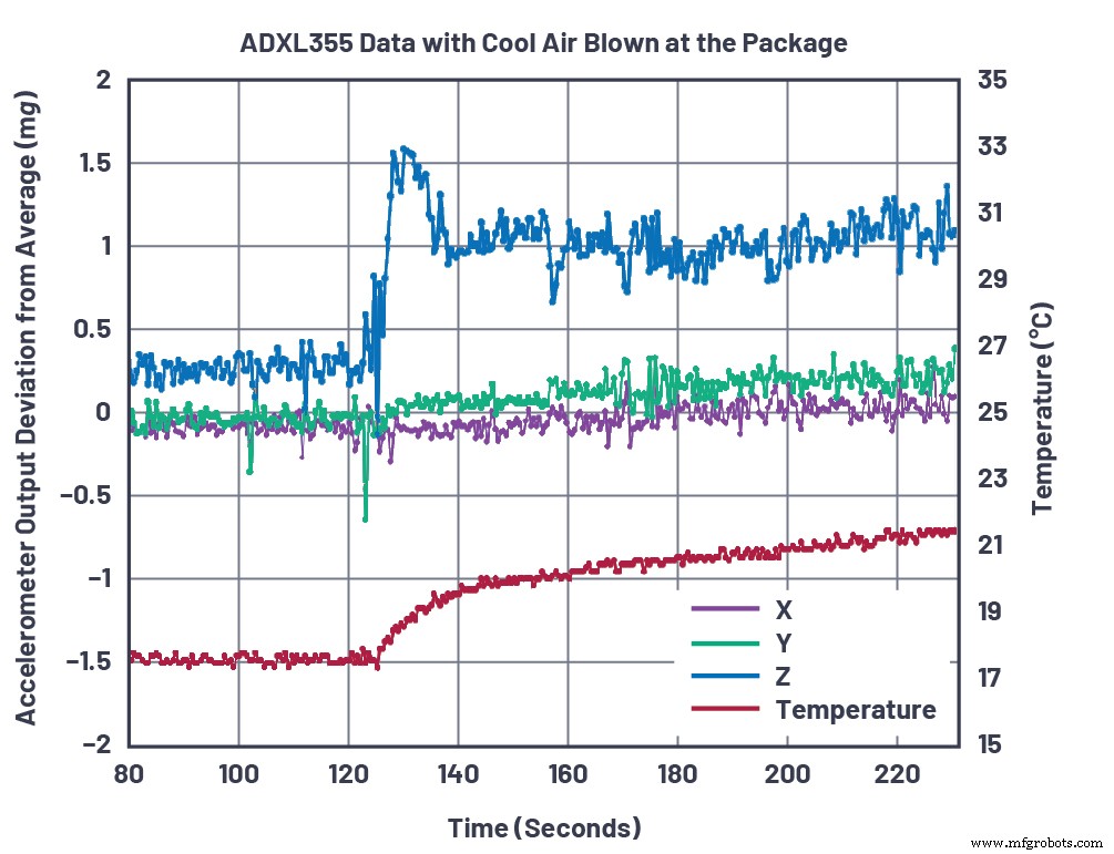
Figure 6. ADXL355 thermal shock data using a hot air gun on cool setting. (Source: Analog Devices)
click for full size image
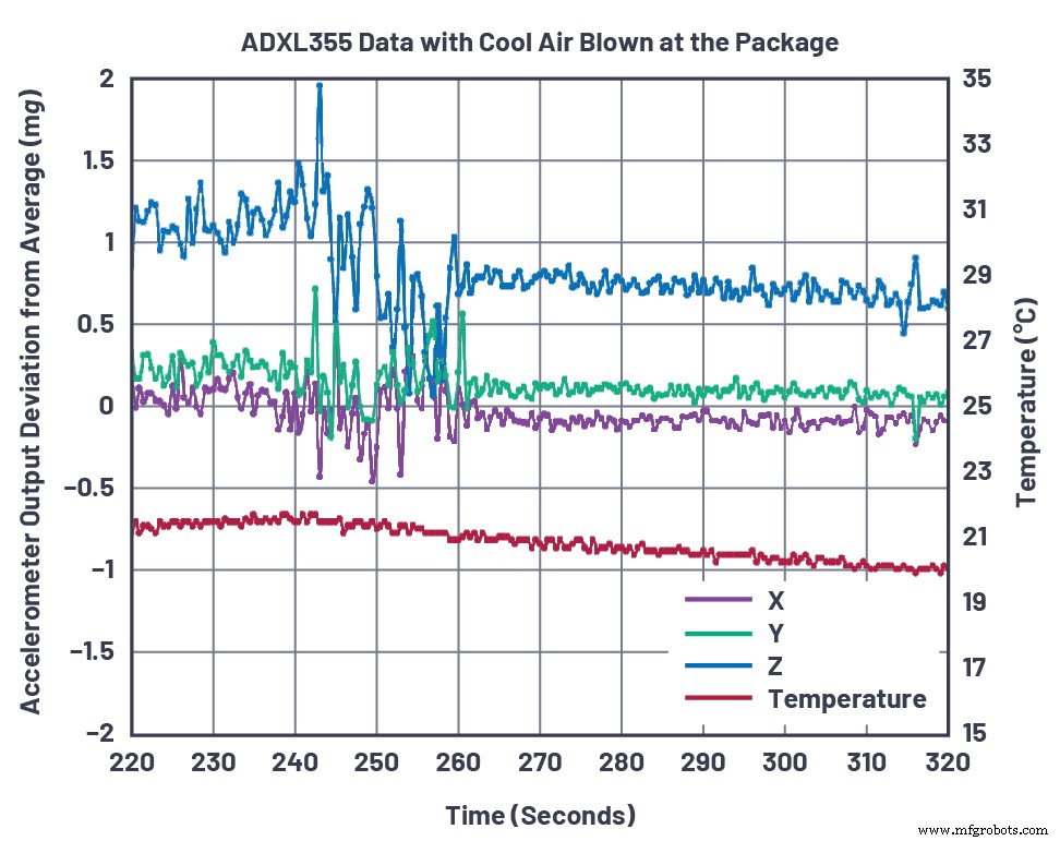
Figure 7. ADXL355 thermal shock with an air gun shutting off at t = 240 seconds. (Source: Analog Devices)
The rapid Z‑axis offset (≈ 10 m g) far exceeds the 100 µg/°C offset temperature coefficient reported in the datasheet. This behavior is attributed to differential thermal stress across the silicon die, which affects the proof mass more strongly in the Z‑direction. In contrast, the 40 °C temperature rise would predict only a 4 m g shift based on the offset coefficient, underscoring that the observed effect is mechanical rather than thermal drift.
Oven‑based temperature characterization (Figure 8) confirms the offset temperature coefficient of roughly 100 µg/°C over the -45 °C to +120 °C range when the sensor is slowly ramped at 5 °C/min without soak. Allowing a 15‑minute soak at 120 °C reduces the effective coefficient to ≈ 60 µg/°C, as the differential stresses equilibrate.
click for full size image
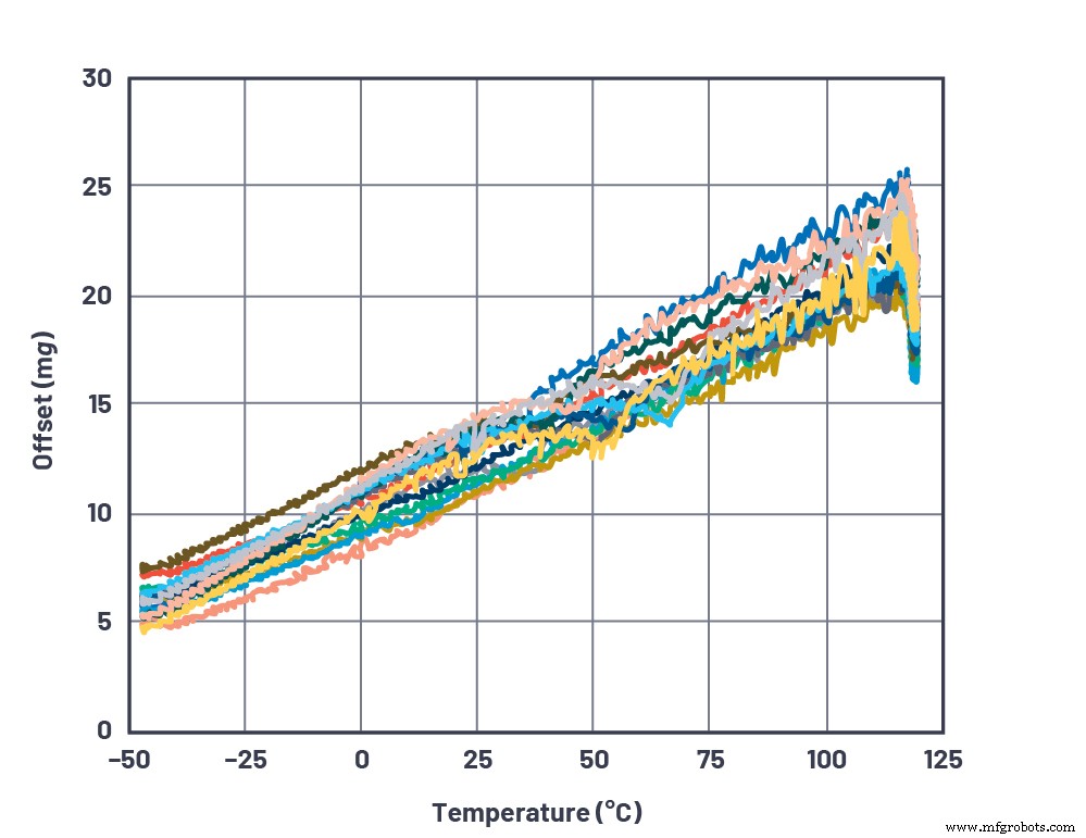
Figure 8. Oven-based temperature characterization of the ADXL355. (Source: Analog Devices)
These baseline measurements confirm that the ADXL355 delivers the advertised low‑noise performance when operated with the appropriate digital low‑pass filter, and that rapid thermal shocks can induce significant offset transients that must be mitigated in design.
In part three of this series we will examine additional factors that influence long‑term stability and provide mechanical design guidelines to further enhance sensor performance.
References
- 1 Chris Murphy, “Choosing the Most Suitable MEMS Accelerometer for Your Application—Part 1,” Analog Dialogue, vol. 51, no. 4, Oct 2017.
- 2 Chris Murphy, “Accelerometer Tilt Measure Over Temperature and in the Presence of Vibration,” Analog Dialogue, Aug 2017.
- 3 SDP‑K1 evaluation system.
- 4 Mbed User Guide for SDP‑K1.
- 5 PanaVise articulated arm mount.
- 6 Mbed code example.
- 7 Weller 6966C heating/cooling air gun.
- 8 Parylene.
Embedded
- Optimizing High‑Precision Tilt Sensing: Accelerometer Fundamentals
- Enhancing Long‑Term Accuracy of 3‑Axis MEMS Accelerometers: Design and Stability Tips
- Six Key Innovations Boosting Cryptographic Hardware Performance
- Designing & Optimizing RTD Temperature Sensing Systems – Expert Guide
- High‑Performance Plastics: Essential Materials for Modern Semiconductor Fabrication
- Robust Precision CNC Turning Centers for High-Performance Job Shops
- Hurco TMX Series: High-Performance Slant-Bed Lathes for Precision Turning
- Why High-Precision Machining Drives Industry Innovation
- High Precision Components: What They Are & Why They Matter
- Set a Reliable Baseline to Maximize System Performance