


Enhancing Long‑Term Accuracy of 3‑Axis MEMS Accelerometers: Design and Stability Tips
In the first two parts of our series we dissected the internal architecture of a 3‑axis high‑precision MEMS accelerometer and showed how to collect a robust baseline dataset that captures the sensor’s intrinsic noise floor. In this final installment we examine the subtle environmental and mechanical factors that can erode long‑term repeatability, and we present concrete design guidelines that help engineers keep performance tight over years of operation.
Once thermal stresses are understood, the next critical aspect is long‑term stability or repeatability. Repeatability measures how closely successive readings agree under identical conditions over an extended period. For example, two gravity‑field measurements taken with the sensor in the same orientation, at the same temperature, and after months of use will be compared to assess drift. Offset and sensitivity repeatability are essential for applications that cannot rely on frequent recalibration. Many manufacturers do not publish long‑term data, but Analog Devices’ ADXL355 datasheet does, providing repeatability figures for a 10‑year life that incorporate high‑temperature operating life tests (HTOL) at 150 °C, 3.6 V supply, 1,000 h; temperature cycling between –55 °C and +125 °C over 1,000 cycles; velocity random walk; broadband noise; and temperature hysteresis. The reported repeatability is ±2 mg for X/Y and ±3 mg for Z, illustrating the sensor’s long‑term performance.
When operating under stable mechanical, environmental, and inertial conditions, repeatability follows a square‑root law with respect to time. For instance, to predict the X‑axis offset repeatability over 2.5 years, the calculation is:
±2 mg × √(2.5 years / 10 years) = ±1 mgFigure 1 demonstrates this relationship using HTOL data: 32 devices show an 0 g offset drift over 23 days. The plot clearly illustrates the square‑root dependence, though individual parts vary due to fabrication process differences.
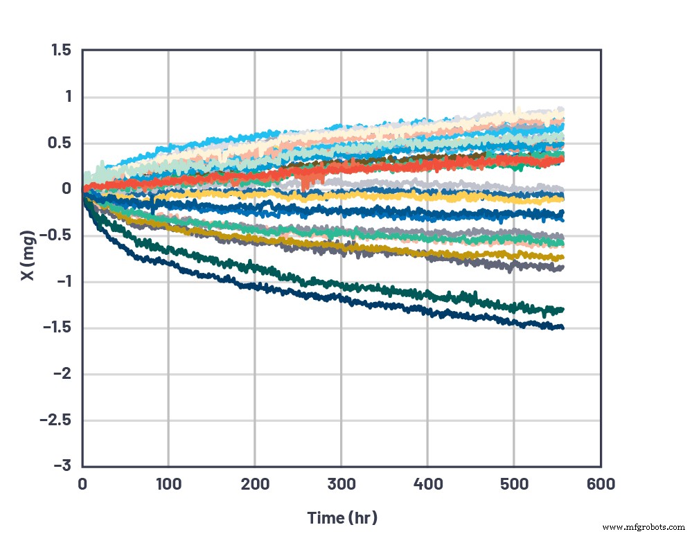
Figure 1. 500‑hour long‑term stability of the ADXL355. (Source: Analog Devices)
Mechanical System Design Recommendations
Mechanical mounting interfaces and enclosure design significantly influence a MEMS accelerometer’s overall performance by transmitting physical stresses to the sensor. The sensor, PCB, and enclosure form a higher‑order system that can behave as a resonant or overdamped structure. Understanding the resonant frequency and quality factor of the mounting system allows engineers to minimize vibrational amplification or excessive damping within the sensor’s bandwidth.
PCB, Mounting, and Enclosure
- Secure the PCB to a rigid substrate using multiple mounting screws combined with backside adhesive for optimal support.
- Place the sensor as close as possible to a mounting point. For large PCBs, use additional screws at the board’s center to suppress low‑frequency flex that could be sensed as acceleration.
- If the board is only supported by a groove or tongue, use a thickness greater than 2 mm. Larger boards benefit from increased thickness to maintain stiffness. Finite‑element analysis (e.g., ANSYS) can identify the optimal geometry and thickness for a specific layout.
- For structural‑health‑monitoring or other long‑term applications, select packaging, PCB, and adhesive materials that resist mechanical property changes over time to avoid added stresses and offset drift.
- Never assume the enclosure’s natural frequency. Perform mode‑shape calculations for simple geometries or full finite‑element analysis for complex enclosures.
- Thermal stresses from soldering can shift offsets by several millig. Symmetric landing patterns, thermal pads, and copper conduction paths help distribute heat evenly. Follow the accelerometer’s soldering guide, and consider solder annealing or pre‑calibration thermal cycling to relieve stress.
Potting Compounds
Potting is common for sealing electronics, but it can impose a temperature‑coefficient mismatch on the sensor if the potting material differs from the enclosure. For land‑grid‑array (LGA) overmolds, potting is discouraged. A hermetically sealed ceramic package offers robust protection against thermal mismatch. However, potting can still generate long‑term stresses due to material degradation, causing subtle warpage that strains the die. In high‑stability applications, avoid potting and consider low‑stress conformal coatings such as parylene‑C to provide a moisture barrier without compromising mechanical integrity.
Air Flow, Heat Transfer, and Thermal Balance
Optimal sensor performance demands careful thermal management:
- Position the sensor so that thermal gradients across its die are minimal. For instance, avoid placing it near heat‑generating components like linear regulators, which can create variable temperature profiles as load changes.
- When possible, locate the module away from airflow sources (e.g., HVAC ducts) to reduce rapid temperature fluctuations. If unavoidable, use thermal isolation—either outside or inside the enclosure—by adding insulation. Both conductive and convective paths must be considered.
- Choose enclosure thermal mass strategically. A larger mass can dampen environmental temperature swings, which is especially useful in applications with inevitable thermal cycling.
Conclusion
Neglecting environmental and mechanical effects can silently degrade a high‑precision MEMS accelerometer’s performance. By adopting a holistic, system‑level design approach—careful mounting, judicious enclosure selection, controlled potting, and thoughtful thermal management—engineers can preserve sensor accuracy over long periods. Just as a well‑designed system tolerates stress, so too can our engineering practices endure the challenges of real‑world operation.
References
- Chris Murphy. “Choosing the Most Suitable MEMs Accelerometer for Your Application—Part 1.” Analog Dialogue, Vol. 51, No. 4, October 2017.
- Chris Murphy. “Accelerometer Tilt Measure Over Temperature and in the Presence of Vibration.” Analog Dialogue, August 2017.
- SDP‑K1 evaluation system. Analog Devices, Inc.
- Mbed: User Guide for SDP‑K1. Analog Devices, Inc.
- PanaVise articulated arm mount. PanaVise.
- Mbed code. Analog Devices, Inc.
- Weller 6966C heating/cooling air gun. Weller.
- Parylene. Wikipedia.
Embedded
- Establishing Baseline Performance for High‑Precision MEMS Accelerometers
- Optimizing High‑Precision Tilt Sensing: Accelerometer Fundamentals
- Designing & Optimizing RTD Temperature Sensing Systems – Expert Guide
- High‑Performance Plastics: Essential Materials for Modern Semiconductor Fabrication
- Robust Precision CNC Turning Centers for High-Performance Job Shops
- Hurco TMX Series: High-Performance Slant-Bed Lathes for Precision Turning
- Grizzly G0740 Toolroom Lathe – 40” Center Distance, 14.17” Swing, Precision‑Engineered for Industrial Use
- Choosing High-Performance CNG & LNG Fittings for Optimal Fuel Efficiency
- Why High-Precision Machining Drives Industry Innovation
- High Precision Components: What They Are & Why They Matter