


Optimizing High‑Precision Tilt Sensing: Accelerometer Fundamentals
Accelerometers are the backbone of modern positioning and monitoring systems, detecting both static orientations relative to gravity and subtle dynamic motions such as early bridge failure. From the low‑cost sensors that tilt your phone’s display to export‑controlled tactical units that guide military vehicles and spacecraft, their performance in the laboratory must translate into reliable field operation amid unpredictable environmental and temperature stresses.
For high‑accuracy tilt systems, calibration typically targets sub‑degree precision. Leveraging market‑leading, ultralow‑noise devices such as the Analog Devices ADXL354 and ADXL355 can deliver tilt accuracies as fine as 0.005° when observable error sources—offsets, temperature drift, vibration rectification, and cross‑axis sensitivity—are properly calibrated. However, stresses on the sensor can introduce offsets of up to 20 mg, which translate into tilt errors exceeding 1°, underscoring the importance of meticulous stress mitigation.
This series explores the performance metrics of high‑precision angle/tilt sensing systems using MEMS accelerometers. In this first installment we dissect the sensor’s microscopic design to illuminate how stresses and strains at the micron level affect accuracy. Subsequent posts will examine surprising failure modes that arise when mechanical and physical design are overlooked, and conclude with actionable strategies for designers to maximize performance in the most demanding applications.
Fundamentals of Sensor Design
MEMS accelerometers span a wide spectrum—from consumer gadgets to military‑grade devices. The highest‑performance low‑noise variants now enable precision tilt sensing, seismic imaging, robotics, and platform stabilization. Key attributes for such applications include exceptional noise performance, minimal offset, high repeatability, low temperature‑drift, and negligible second‑order effects such as vibration rectification and cross‑axis sensitivity.
To appreciate why a 3‑axis MEMS accelerometer behaves differently along each axis, it is instructive to examine its internal architecture. Figure 1 below shows the ADXL355’s spring‑mass system: a proof mass moves under acceleration, and its displacement is sensed via a transduction mechanism. The X/Y axes employ differential in‑plane capacitive fingers, whereas the Z axis uses an out‑of‑plane parallel‑plate capacitor.
click for full size image
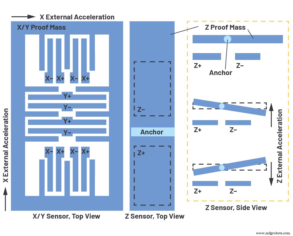
Figure 1. Sensor architecture of the 3‑axis ADXL355 from Analog Devices. The X/Y proof mass moves laterally, altering capacitance between anchored and movable fingers. The Z axis senses out‑of‑plane motion via a parallel‑plate capacitor.
When compressive or tensile stress warps the die, the suspended proof mass does not follow the substrate. This alters the gap between mass and substrate. For X/Y sensors, the in‑plane gap is largely compensated by fringe fields, so the effect is modest. The Z sensor, however, relies directly on this gap; warpage therefore produces a direct offset in the Z reading. The Z sensor’s central location on the die further magnifies its susceptibility to warpage.
Temperature gradients across the z‑axis are also common, stemming from asymmetric heat transfer: conduction through solder at the bottom versus convection on the top. This residual differential temperature introduces an offset that is not related to acceleration, further compromising tilt accuracy if uncorrected.
In the next article of this series, we will cover how to acquire a robust baseline dataset, validate expected noise levels, and set the stage for advanced calibration techniques.
References
[1] Chris Murphy. “Choosing the Most Suitable MEMs Accelerometer for Your Application—Part 1.” Analog Dialogue, Vol. 51, No. 4, October 2017.
[2] Chris Murphy. “Accelerometer Tilt Measure Over Temperature and in the Presence of Vibration.” Analog Dialogue, August 2017.
Embedded
- Achieving High-Precision Temperature Measurements with Advanced Silicon Sensors
- Establishing Baseline Performance for High‑Precision MEMS Accelerometers
- Enhancing Long‑Term Accuracy of 3‑Axis MEMS Accelerometers: Design and Stability Tips
- Digital Magnetic Hall Sensors: Fundamentals, Design, and Automotive Applications
- Advanced Sensors Empower Wearable Health Tech: From Heart Rate to Temperature Accuracy
- Designing & Optimizing RTD Temperature Sensing Systems – Expert Guide
- MLX91377 Hall Sensor: High‑Linearity, Thermal‑Stable, ASIL‑Ready for Automotive Safety
- Deep Dive into MEMS Actuation & Sensing Mechanisms: Your Guide to Advanced Sensor Design
- Calculate Tilt Angles from MPU6050 Acceleration Using Arduino Nano
- Digital Sensors in Industrial Machinery: Function, Types, and Best Practices