


Designing & Optimizing RTD Temperature Sensing Systems – Expert Guide
In the second article of our three‑part series on resistance temperature detectors (RTDs), we dive into system optimization, component selection, and performance evaluation.
Recap of Part 1
The first article covered temperature measurement challenges, RTD types, configurations, and the basic RTD circuit. Part 2 focused on the three wiring configurations—2‑wire, 3‑wire, and 4‑wire. In this final installment, we explore how to fine‑tune an RTD system for peak accuracy.
RTD System Optimization
Designing a robust RTD solution involves three key decisions:
- Sensor selection & wiring diagram – Choose the appropriate RTD and connection method.
- Measurement configuration – Set ADC parameters, excitation current, gain, and external components while staying within ADC limits.
- Error budget – Identify and mitigate all contributors to the overall system error.
Analog Devices offers the RTD Configurator & Error Budget Calculator to streamline these choices from concept to prototype.
The tool:
- Guides you through proper wiring, circuit diagrams, and excitation settings.
- Highlights error sources and suggests design optimizations.
Designed for the AD7124‑4/AD7124‑8, the configurator lets users adjust excitation current, gain, and external components (see Figure 1). It flags out‑of‑spec conditions so the final solution respects ADC constraints.
click for full size image
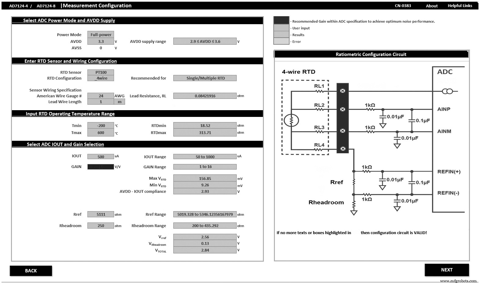
Figure 1. RTD configurator. (Source: Analog Devices)
Choosing Excitation Current, Gain, & External Components
Higher excitation currents yield larger output voltages and better ADC utilization, but they also raise sensor self‑heating. To balance these effects, designers can:
- Use a high excitation current with intermittent operation to minimize heating.
- Adopt a lower current and compensate with higher ADC gain.
Key considerations:
- Self‑heating – Evaluate the temperature rise for the chosen current.
- Timing – Inter‑measurement gaps required for the sensor to return to steady state.
- ADC compliance – Ensure the excitation voltage remains within the ADC’s supply headroom.
The AD7124 series supports PGA gains from 1 to 128, enabling designers to match the excitation current to the sensor’s dynamic range. The configurator also recommends precision reference resistors and headroom resistors, guaranteeing operation within ADC limits.
Filtering for Antialiasing & Power Line Rejection
Sigma‑delta ADCs like the AD7124 require antialiasing filters. A simple single‑pole RC on the analog input, complemented by digital filtering, effectively attenuates 50/60 Hz mains interference and harmonics. The AD7124 offers programmable digital filters (sinc1, sinc2, sinc3, sinc4, FIR) that can place notches at 50 Hz/60 Hz, allowing designers to balance data‑rate, settling time, and noise rejection.
For multi‑channel systems, selecting a filter with a longer settling time (e.g., sinc4) reduces throughput. A post‑filter or FIR can maintain high rejection while keeping throughput acceptable.
Power Management
Power budgets vary by application. The AD7124 provides three modes:
- Low‑Power – Ideal for battery‑operated or 4 mA loop systems.
- Mid‑Power – Balances speed and energy consumption.
- Full‑Power – Maximizes data rate for mains‑powered industrial control.
Error Sources & Calibration
After configuring the system, estimating error contributions is critical. The RTD Error Calculator presents a comprehensive error budget (see Figure 2). Typically, the reference resistor’s accuracy and temperature coefficient dominate the error. Choosing a 0.01 % reference resistor with a low TCR can reduce this term substantially.
click for full size image
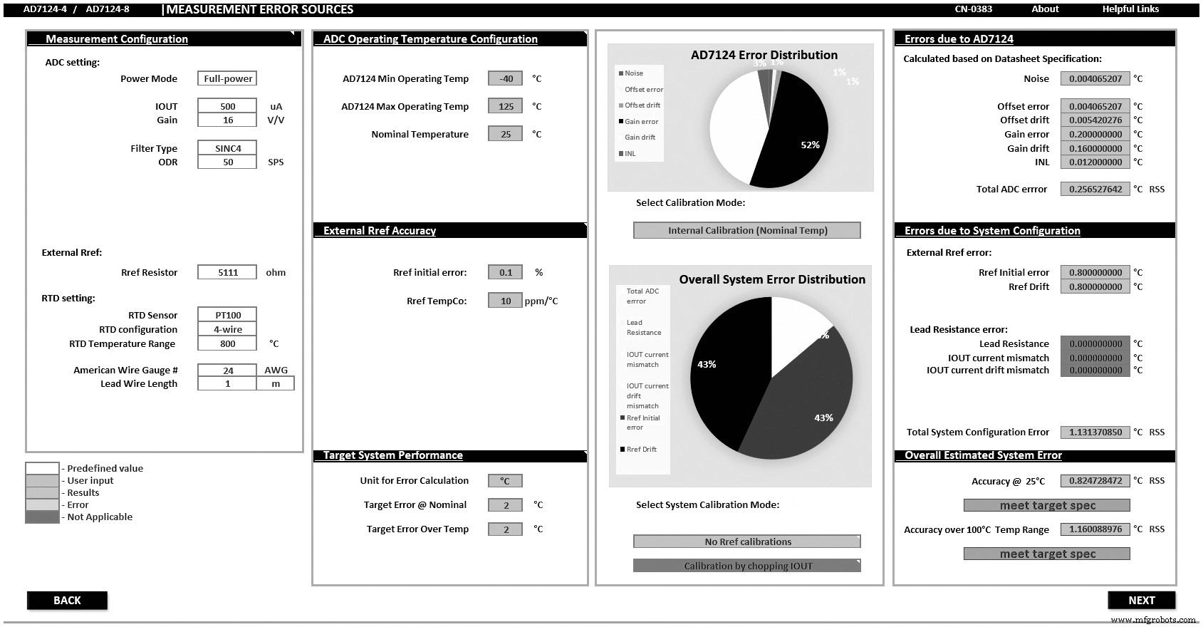
Figure 2. RTD error sources calculator. (Source: Analog Devices)
Internal calibration of the AD7124 removes gain and offset errors on power‑up or software reset. System‑level calibration can further reduce errors but adds cost and complexity. For most applications, internal calibration combined with high‑accuracy reference components suffices.
Fault Detection & Diagnostics
Safety‑critical environments benefit from built‑in diagnostics. The AD7124’s embedded checks include:
- Analog pin voltage range verification.
- SPI and memory map CRC checks.
- Signal‑chain integrity monitoring.
System Evaluation & Validation
Figure 3 shows real‑world data from the AD7124 evaluation board (CN‑0383). The board supports 2‑, 3‑, and 4‑wire RTDs and includes demo modes for quick verification.
click for full size image
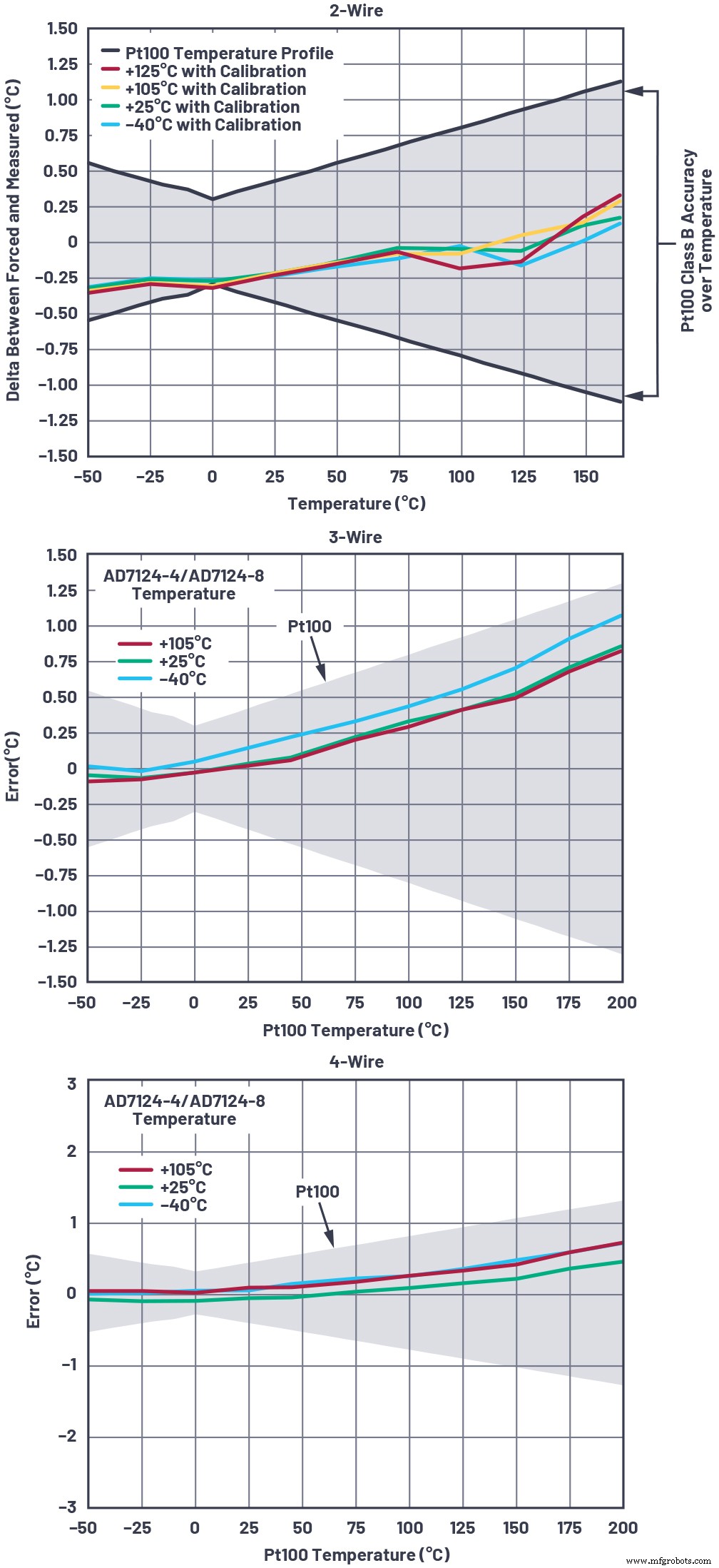
Figure 3. 2‑/3‑/4‑wire RTD temperature accuracy measurement postfilter in low‑power mode at 25 SPS. (Source: Analog Devices)
The 2‑wire configuration shows errors near the lower bound due to lead resistance, while 3‑wire and 4‑wire designs comfortably stay within the specified limits. These results confirm that following the outlined guidelines yields high‑accuracy, high‑performance RTD systems when paired with the AD7124 sigma‑delta ADC.
For rapid prototyping, use the CN‑0383 reference design, the evaluation board, and the provided sample firmware. The AD7124’s comprehensive ecosystem—configurator, VirtualEval, evaluation hardware, and source code—streamlines the design cycle from concept to production.
Conclusion
Designing a precision RTD measurement system is a multi‑step process that demands careful selection of sensor configuration, ADC, excitation, filtering, and calibration. By leveraging the RTD Configurator & Error Budget Calculator, VirtualEval, evaluation board, and CN‑0383, engineers can efficiently navigate connectivity challenges, error budgets, and performance trade‑offs to deliver reliable, high‑accuracy RTD solutions.
 Jellenie Rodriguez is an applications engineer at Analog Devices within the Precision Converter Technology Group. Her focus is on precision sigma‑delta ADCs for DC measurements. She joined ADI in 2012 and graduated from San Sebastian College‑Recoletos de Cavite with a bachelor’s degree in electronics engineering in 2011. She can be reached at jellenie.rodriguez@analog.com.
 Mary McCarthy is an applications engineer at Analog Devices. She joined ADI in 1991 and works in the Linear and Precision Technology Applications Group in Cork, Ireland, focusing on precision sigma‑delta converters. Mary graduated with a bachelor’s degree in electronic and electrical engineering from University College Cork in 1991. She can be reached at mary.mccarthy@analog.com.
Related Contents:
- Optimizing RTD temperature sensing systems: Challenges (Part 1)
- Optimizing RTD temperature sensing systems: Wiring configurations (Part 2)
- Using a delta‑sigma ADC in high‑precision multisensor systems
- Performing precision measurement with silicon temperature sensors
- Interfacing with modern sensors: Interface design using C++
- Tackling high‑temperature data acquisition and processing platform development
For more Embedded, subscribe to Embedded’s weekly email newsletter.
Embedded
- Common Pitfalls in New Systems: How to Avoid Early Failures
- Designing Fail‑Safe Control Systems for Safety and Reliability
- Embedded System Design: Steps, Principles, and Real‑World Applications
- Connectivity by Design: Unlocking Unified Data for Digital Twins and Real‑Time Decision‑Making
- Optimizing Grounded Coplanar Waveguide RF Feedlines for Enhanced Wi‑Fi Performance
- Embedded FPGA Design: A Complete Development Process
- Linux Foundation & IBM Back OpenEEW: A Low‑Cost IoT Solution for Earthquake Early Warning
- Mastering Control System Design: From Basic Panels to Advanced, Reliable Solutions
- Optimizing Illumination Design for Robotic Surgery Vision Systems
- Optimize Conveyor Performance with Tailored Support Systems