


Efficient AVR Development Using Programmable GreenPAK ASICs
Modern Automatic Voltage Regulators (AVRs) increasingly rely on digital control, yet the cost‑effective, compact solutions offered by programmable mixed‑signal ASICs—such as Dialog Semiconductor’s GreenPAK SLG46537V—are proving especially valuable for portable AVR units.
AVRs, commonly referred to as voltage stabilizers, maintain a steady output voltage by compensating for fluctuations in the supply. They are integral to generators on ships, emergency power systems, and oil rigs, and they protect consumer appliances like air conditioners and refrigerators from voltage irregularities.
For utilities, accurate voltage regulation across the distribution network is essential for power quality. In regions such as South Asia, challenges like power theft and generation shortages can trigger load shedding and voltage swings, making portable AVRs a popular safeguard.
Traditional AVR designs employ a tapped autotransformer with a relay‑driven feedback loop. The circuit typically consists of a sensing unit that monitors input and output voltages and a regulating unit that drives relays to select the correct transformer tap. Historically, this feedback was implemented with op‑amp ICs and analog comparators; more recent designs use 8‑bit microcontrollers. However, the GreenPAK platform delivers equivalent functionality at lower cost and footprint, eliminating the need for separate MCU firmware.
In the following sections we detail how the SLG46537V can be configured as the AVR controller, present the full system architecture, and share experimental results from a prototype.
System Architecture
Figure 1 shows the block diagram of the AVR. The AC output is conditioned to a DC level suitable for the GreenPAK, which in turn drives electromechanical relays to select the appropriate autotransformer tap. The controller also powers the relay driving circuitry and provides LED status indicators.
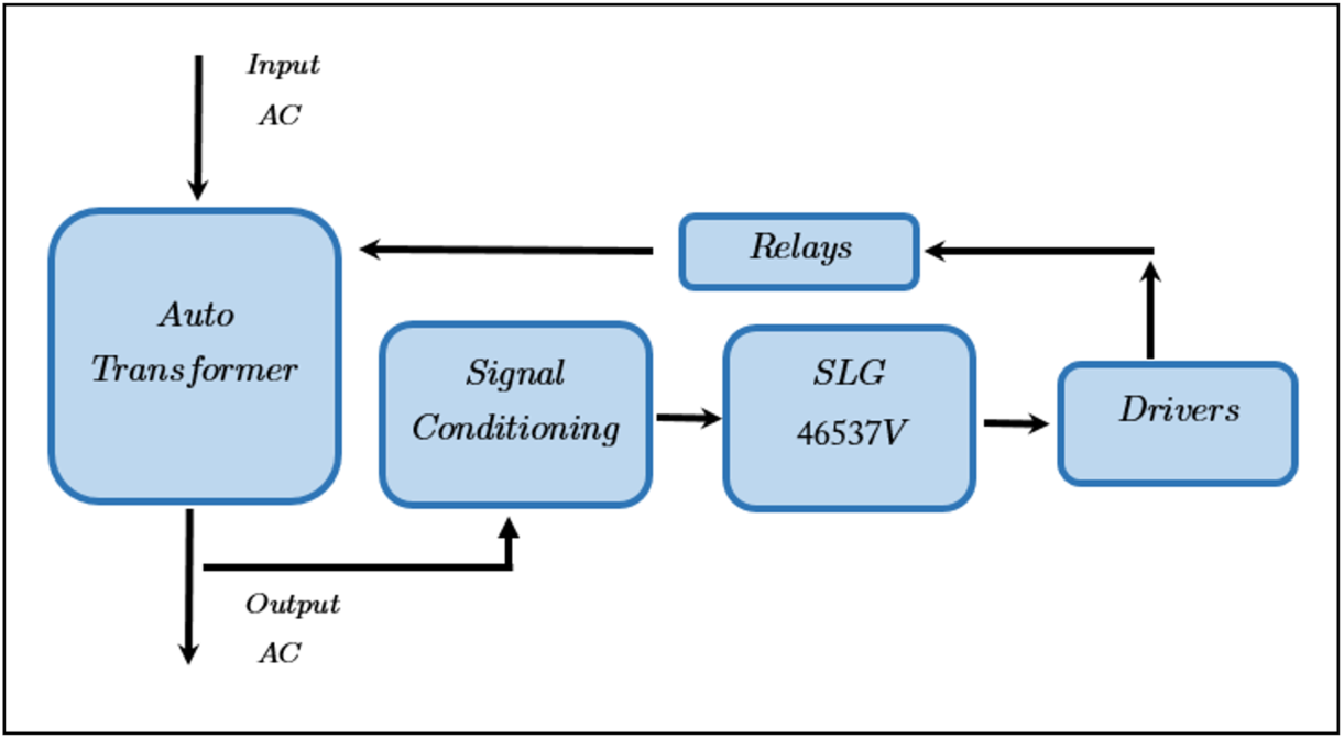
Figure 1: Functional block diagram (source: BarqEE)
The AVR’s key specifications are:
- Input voltage: 125 V – 240 V
- Regulated output: 200 V – 240 V
- Undervoltage protection (<180 V) and overvoltage protection (>255 V) disconnect the output.
- Four electromechanical relays drive the autotransformer taps (135 V, 174 V, 196 V, 220 V) and a safety relay.
- Output waveform and frequency match the input.
- Cost‑effective controller design.
- LED indicators for normal, overvoltage, and undervoltage states.
These parameters can be adjusted in the GreenPAK firmware to suit other applications.
Functional Implementation
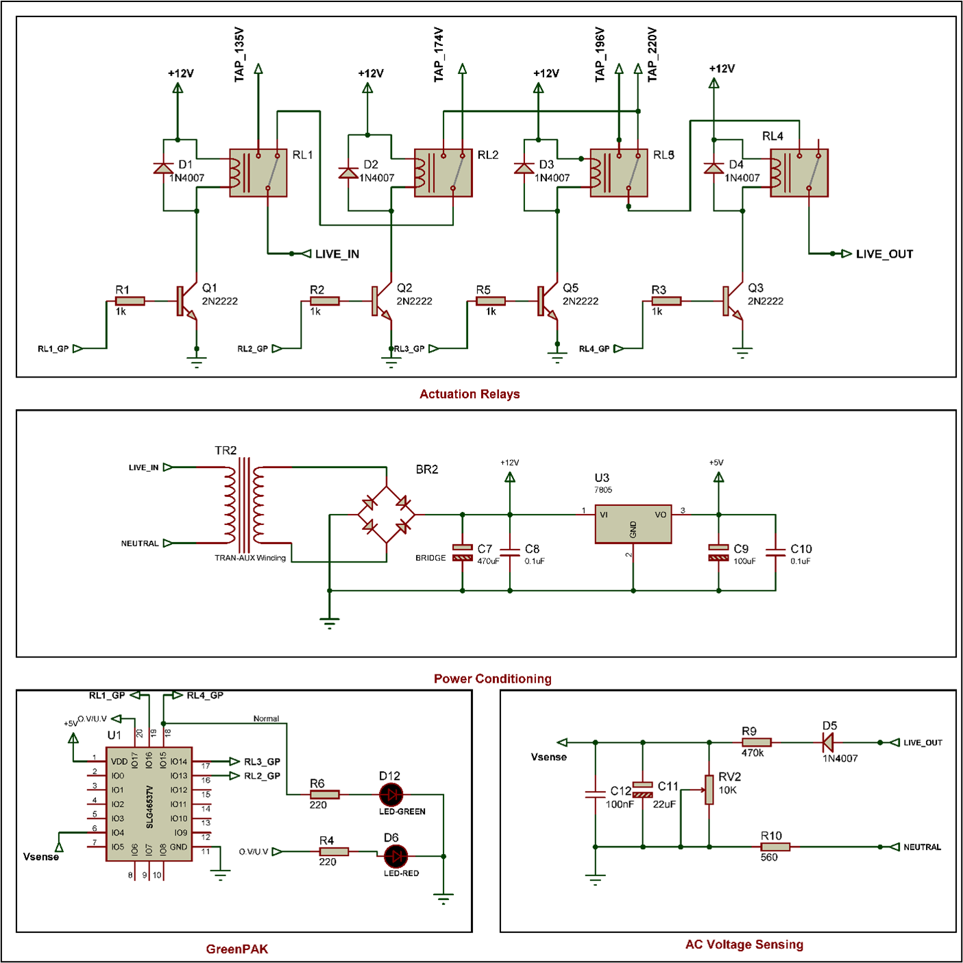
Figure 2: Detailed AVR architecture (source: BarqEE)
Power Conditioning
The live AC is stepped down to 12 V and then regulated to 5 VDC to power the GreenPAK.
Voltage Sensing
The output AC (Live_out) is attenuated, rectified, and filtered to produce a stable DC reference (Vsense). A 0.01 scaling factor converts 200 VAC to ~2 VDC, matching the IC’s input range.
GreenPAK Control
Vsense feeds the GreenPAK’s comparators and state machine. Digital outputs drive transistor‑based relay drivers and LED status LEDs. The schematic of the GreenPAK IO configuration is shown in Figure 3.
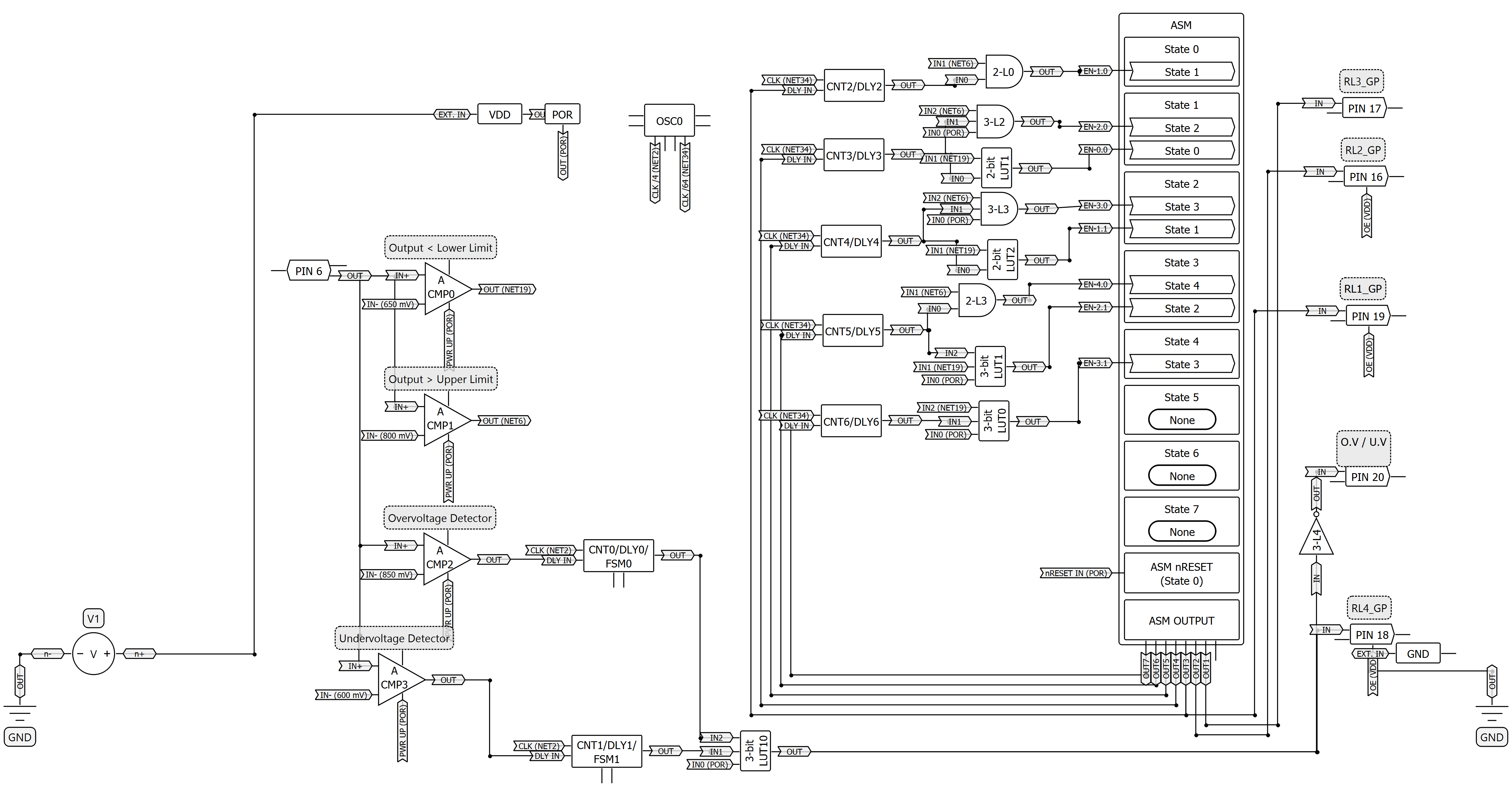
Figure 3: GreenPAK design schematic (source: BarqEE)
Relay Actuation
Three relays (RL1–RL3) switch the transformer input between the four taps. A fourth relay (RL4) disconnects the output under protection conditions.
GreenPAK Logic Design
The GreenPAK Designer file is available here (free download).
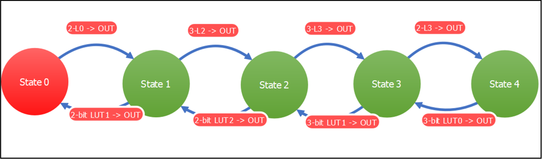
Figure 4: Five‑state finite state machine (source: BarqEE)
The FSM controls relay selection: each state maps to a specific autotransformer tap ratio, as summarized in Table 1.
Table 1: Autotransformer tap ratios per state (source: BarqEE)
| State | Tap ratio |
|---|---|
| 0 | 220/135 ≈ 1.63 |
| 1 | 196/135 ≈ 1.45 |
| 2 | 220/174 ≈ 1.26 |
| 3 | 196/174 ≈ 1.13 |
| 4 | 220/220 = 1 |
State transitions occur when the sensed output voltage exits the 200 V–240 V band. Delays of ≈ 0.5 s prevent relay chatter during transient excursions.
Overvoltage and undervoltage are detected by comparators ACMP2 and ACMP3. After a 50 ms debounce, the logic disables RL4 and activates the corresponding LED.
Experimental Validation
Hardware Setup
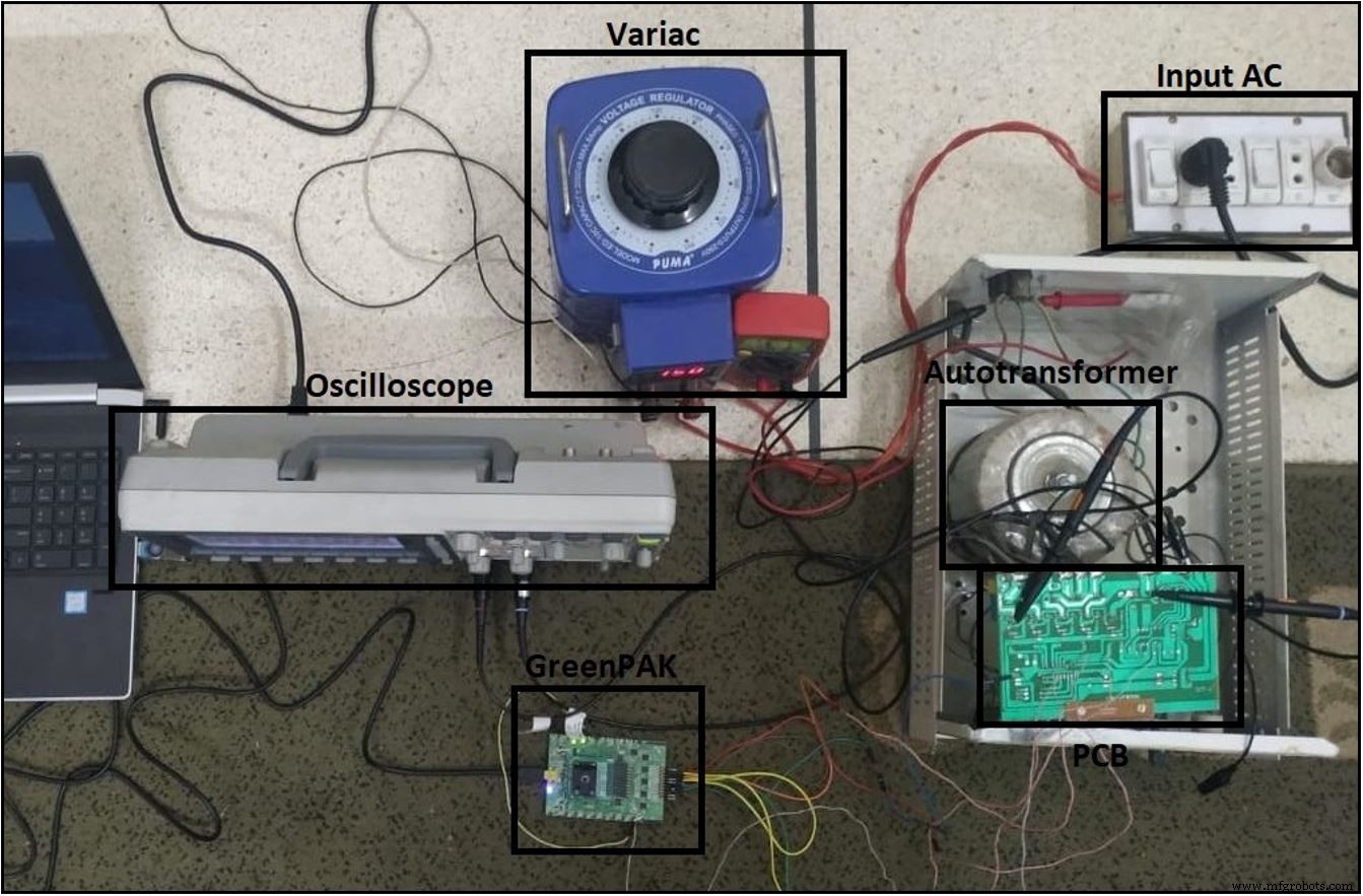
Figure 6: Prototype test bench (source: BarqEE)
The test harness uses a Variac to sweep the input voltage, an oscilloscope to capture waveforms, and a GreenPAK development board to drive the relays.
PCB and Relay Circuit
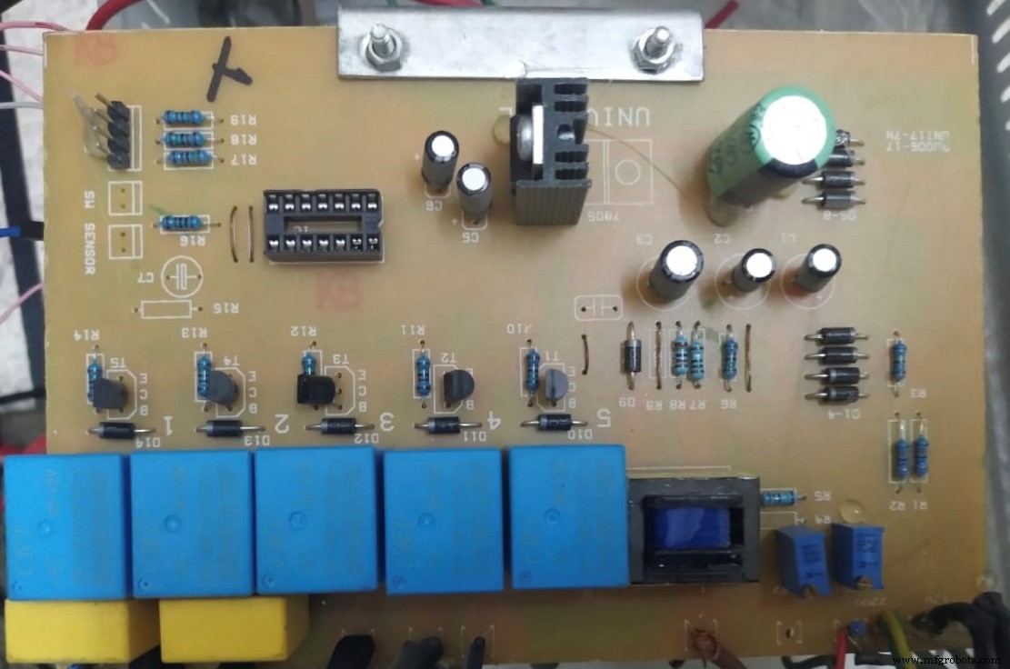
Figure 7: PCB layout (source: BarqEE)
The board hosts the relay drivers, BJTs, and ancillary components.
Performance Metrics
- Load: 450 VA – 550 VA
- Input voltage: 125 V – 240 V
- Output voltage: 200 V – 240 V
- Frequency: 50 Hz – 60 Hz
- Insulation resistance: > 5 MΩ
- Response time: 10 ms – 15 ms
- Transformer temperature rise: 65 °C – 70 °C at 1.2× rated load
- Efficiency: > 95 %
- Ambient temperature range: –40 °C to 0 °C
Waveform Analysis
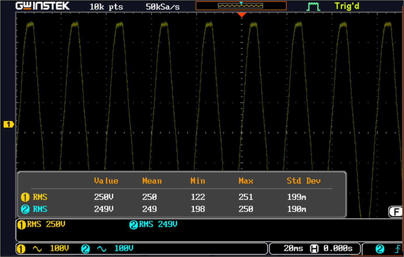
Figure 8: Quantitative oscilloscope results (source: BarqEE)
The AVR tracks the input voltage and maintains the output within the target band by cycling through the relay taps.
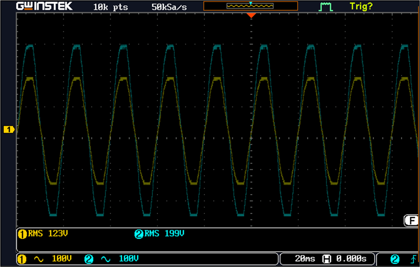
Figure 9: Normal regulation (source: BarqEE)
When the input rises toward the upper limit, the AVR shifts to the lowest tap ratio (1.00) to bring the output back to 200 V–240 V.
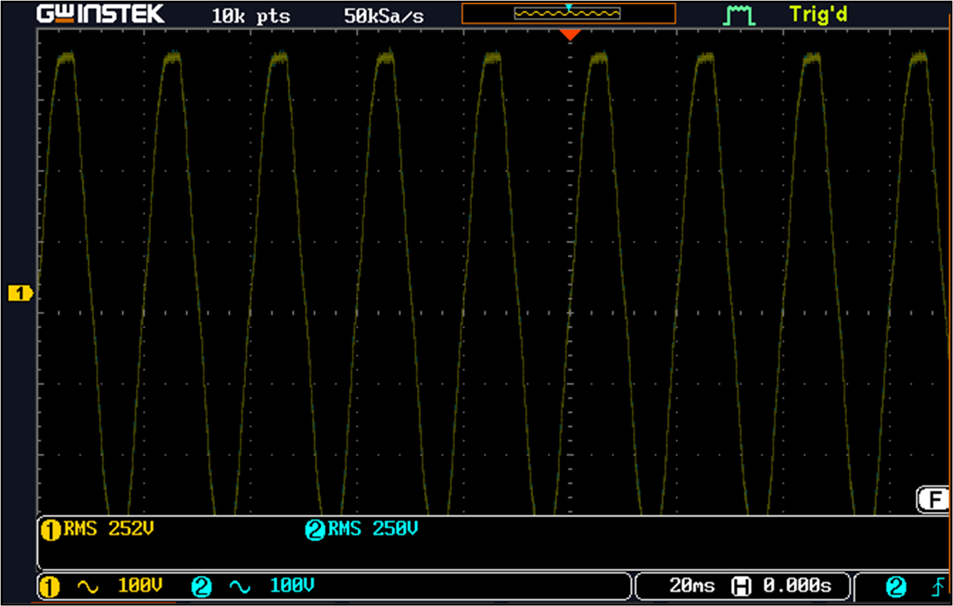
Figure 10: Approaching overvoltage (source: BarqEE)
During an overvoltage excursion, RL4 opens and the output collapses, protecting the load.
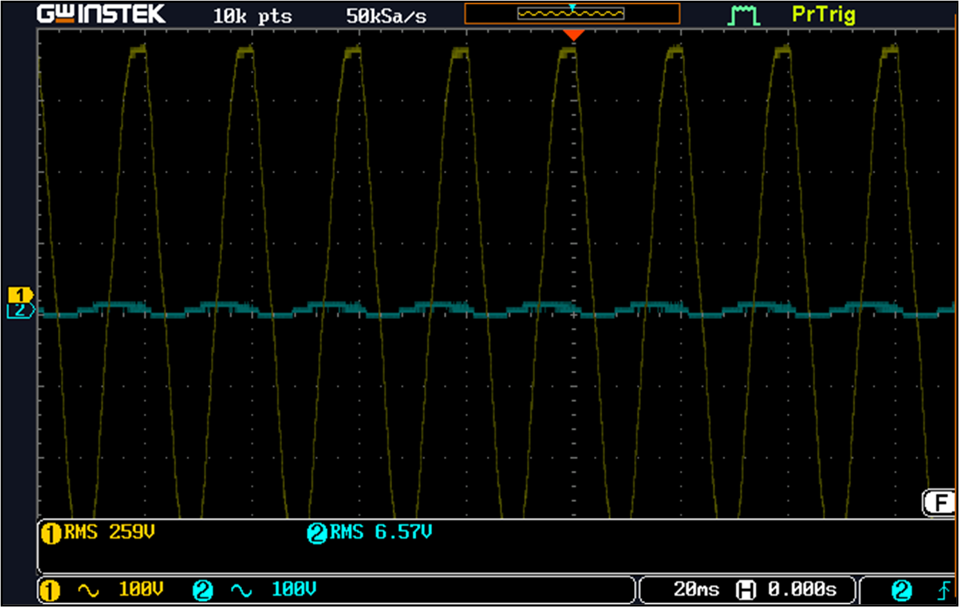
Figure 11: Overvoltage protection (source: BarqEE)
Analogous protection occurs under undervoltage conditions, as illustrated in Figures 12 and 13.
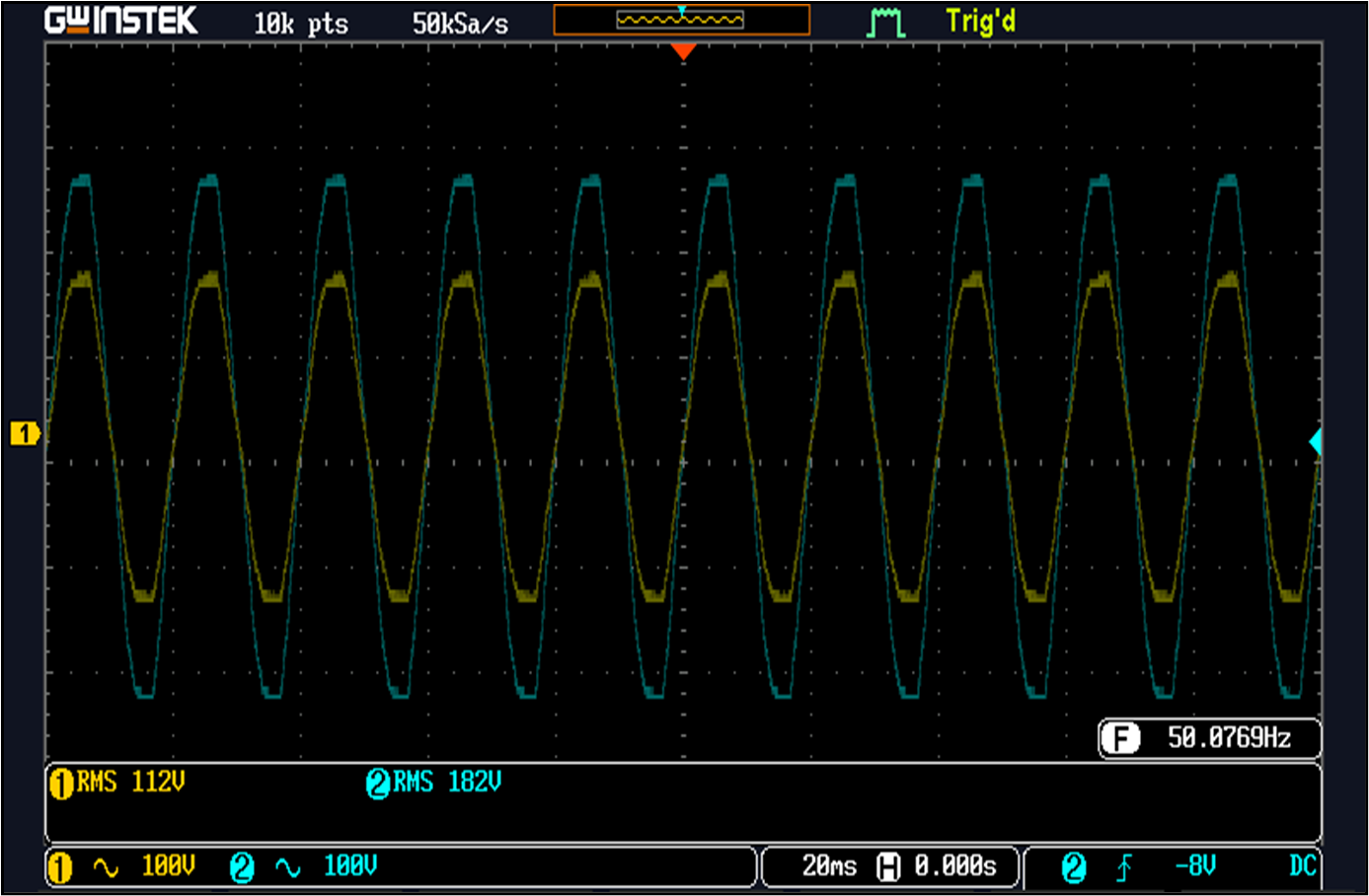
Figure 12: Approaching undervoltage (source: BarqEE)
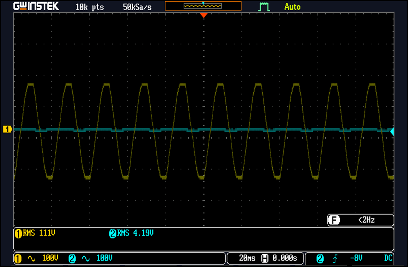
Figure 13: Undervoltage protection (source: BarqEE)
Throughout regulation, the output frequency and phase remain identical to the input.
Conclusion
Programmable ASICs like the GreenPAK SLG46537V can replace discrete AVR controllers and microcontrollers, delivering reliable voltage regulation at lower cost and PCB area. The prototype demonstrates the feasibility of this approach for residential and industrial applications, and the architecture can be scaled to more complex controllers by leveraging ASICs with additional FSM states.
Aamir Hussain Chughtai is a Ph.D. candidate in Electrical Engineering at LUMS, Lahore. His research focuses on signal processing, machine learning, and IoT. He co‑founded BarqEE and can be contacted at chughtaiah@barqee.com.
Muhammad Saqib holds an M.S. in Electrical Engineering from NUCES, Lahore. His expertise includes power electronics, embedded systems, and instrumentation. He co‑founded BarqEE and can be reached at saqib.awan@barqee.com.
Related contents:
- Fully‑programmable SoCs – A new breed of devices
- High‑performance embedded computing – Hardware accelerators
- Designing a fast‑reacting feedback system for miniaturized motor‑driven designs
- Analog sampling: what do accuracy, sensitivity, precision, and noise mean?
- Saving power with relays and solenoids
Subscribe to Embedded’s weekly email newsletter for more embedded content.
Embedded
- Understanding Polarity and Phase in AC Circuit Analysis
- Top 7 Manufacturing Trends Shaping 2020 and Beyond
- Establishing Robust Quality Control for 3D Printing Success
- Maximizing the Impact of Condition‑Based Maintenance: A Practical Guide
- 50 Proven Strategies to Build a High‑Performance Maintenance Program
- ATI Industrial Automation: Leading Automatic Tool Changers for Industrial Robots
- Smart Pet Food Catapult – Automatically Toss Treats, Balls, and Toys for Your Furry Friends
- Advanced Camshaft Machining Techniques for Peak Performance
- MD&M West 2018 Showcases Advanced Technologies for Efficient Medical Component Manufacturing
- New Chemistry Method Enhances Durability of Soft Electronics