


Power over Ethernet (PoE) Fundamentals: Delivering DC Power Over Data Cables
Power over Ethernet (PoE) enables the delivery of DC power—up to 90 W—across standard Ethernet cables over distances of up to 100 meters. This technology combines power and data into a single cabling infrastructure, simplifying installations in commercial, industrial, and enterprise environments.
Editor’s Note: Delivering power and data over one cable is a game‑changer for modern networks. Just as USB has become ubiquitous for consumer devices, PoE offers a scalable, secure, and cost‑effective solution for connected infrastructure.
The National Fire Protection Association (NFPA) lists electrical and lighting equipment as the third leading cause of commercial fires in the U.S. Common culprits include aging wiring, overloaded circuits, loose connections, faulty fuses, and imbalanced loads—all of which can overheat and spark a fire. PoE’s built‑in power management mitigates these risks by controlling voltage, current, and load protection at the silicon level.
Mains power supplies long‑haul AC power across three insulated conductors: live (120 V or 230 V AC), neutral (near 0 V), and earth (ground). The earth conductor, which can consume up to 33% of the total copper cross‑section, is essential for safety. In contrast, PoE uses the eight conductors of an Ethernet cable to deliver DC power, freeing copper for data and handling safety through integrated silicon controls.
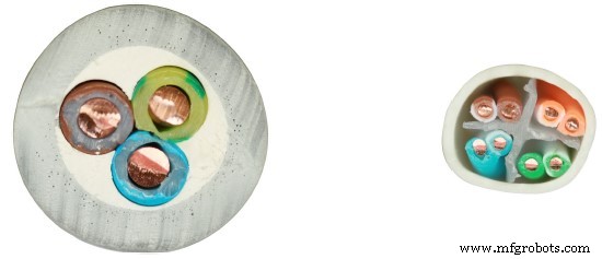
Figure 1: Comparison of a 2.5 mm² mains wire and a 23 AWG CAT6 cable (source: Ethernet Alliance)
2‑Pair Power vs. 4‑Pair Power
RJ45 connectors provide eight contacts divided into four differential pairs. In 10BASE‑T and 100BASE‑TX networks, only two pairs carry data, leaving two pairs unused. Gigabit Ethernet uses all four pairs. PoE takes advantage of the unused pairs (IEEE 802.3af) or all four pairs (IEEE 802.3bt) to supply power.
IEEE 802.3af (PoE) delivers 350 mA per pair at a maximum of 57 V. IEEE 802.3at (PoE+) raises this to 600 mA per pair, still at 57 V. IEEE 802.3bt (PoE 2) uses all four pairs, each at 960 mA, reaching up to 90 W per port.
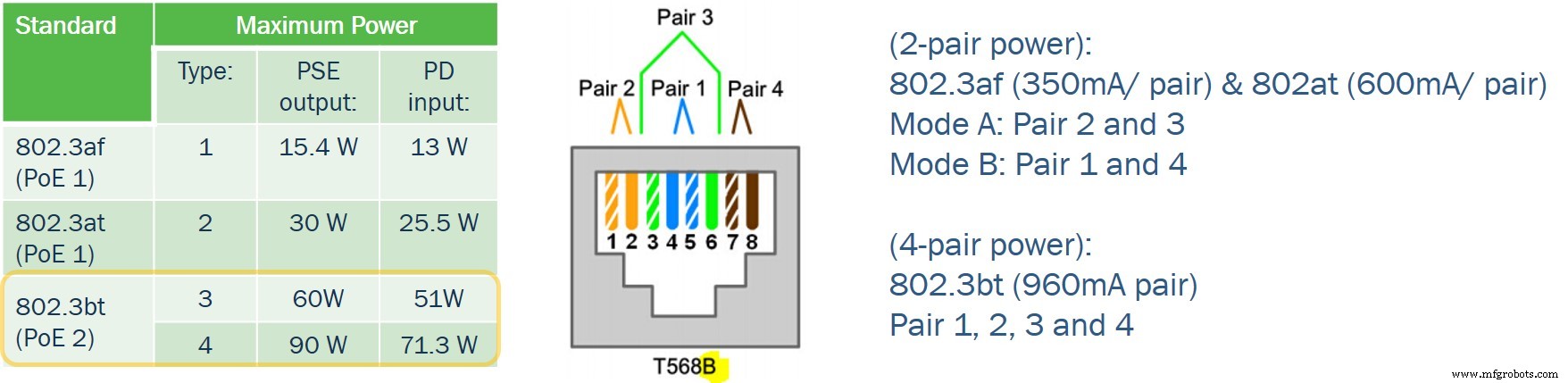
Figure 2: 2‑pair versus 4‑pair power provisioning
IEEE 802.3bt (90 W) Classification
The Ethernet Alliance further subdivides PoE 2 into eight classes (5–8), each representing a 15 W slice for the PSE and an 11 W slice for the PD. This granular approach allows multi‑port PSEs to allocate power efficiently based on each device’s needs.
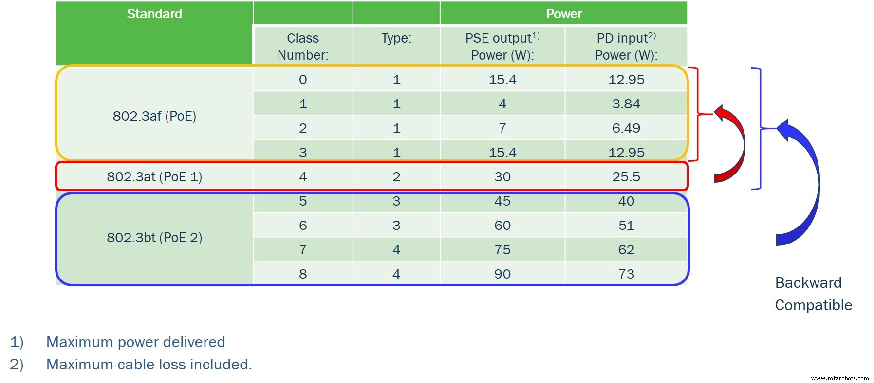
Figure 3: IEEE 802.3bt class and type breakdown
PoE Power Provisioning Phases
PoE follows a five‑step provisioning cycle, as illustrated below.
- Detection
- Classification
- Startup
- Operation
- Disconnect
The PSE incorporates an Rsense resistor to measure current drawn by the PD, while a 25 kΩ pull‑down resistor on the PD signals detection.
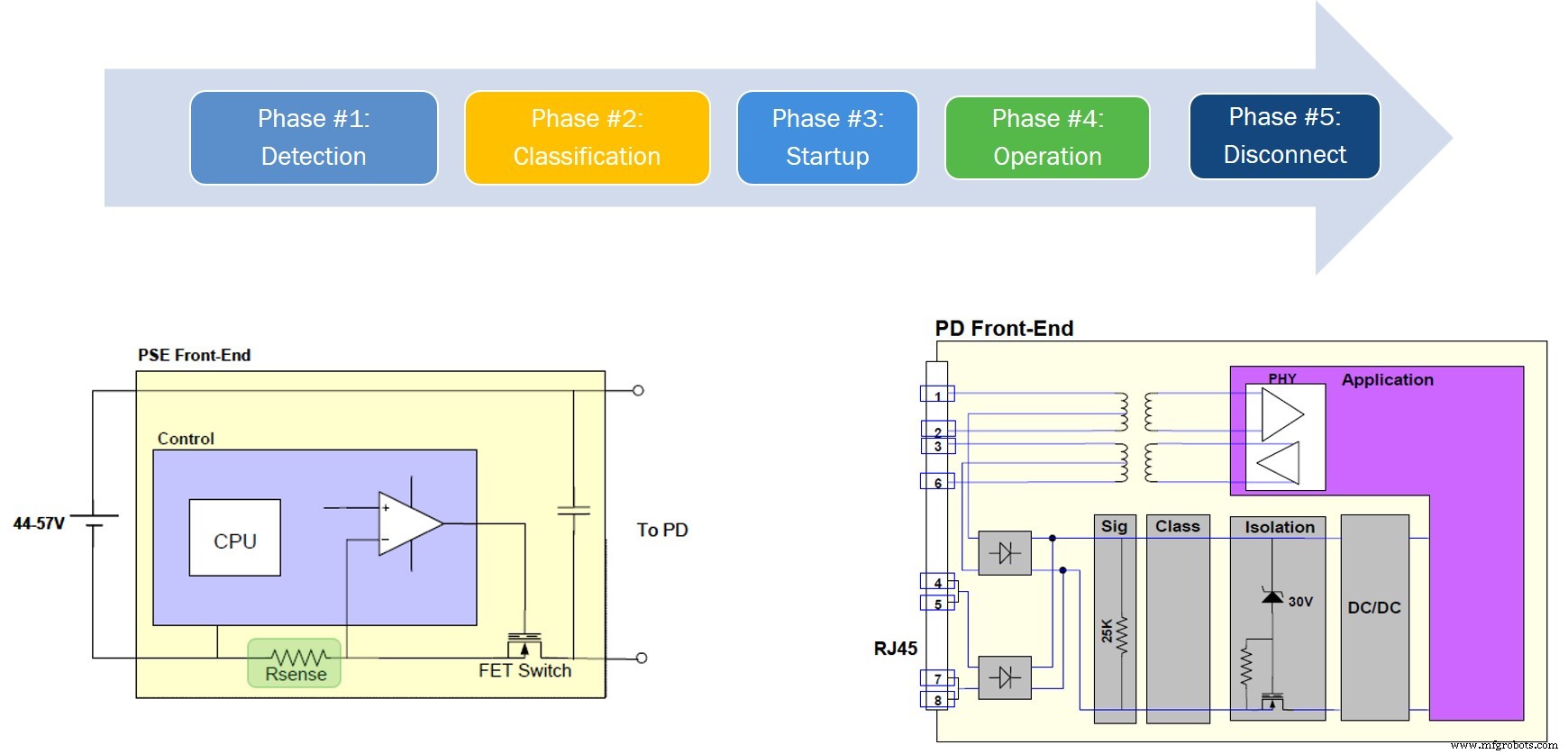
Figure 4: PoE power provisioning phases (source: Ethernet Alliance)
Phase 1 – Detection
Upon connection, the PD’s 25 kΩ pull‑down resistor prompts the PSE to perform two voltage‑current measurements within a 500 ms window: 2.8 V and 10 V. By computing the ΔV/ΔI ratio, the PSE confirms the presence of a PoE‑capable device. A valid detection range is 19 kΩ to 26.5 kΩ; otherwise, the PSE rejects the device.
Phase 2 – Classification
During classification, the PD announces its required power class via five timed “class events.” Each event corresponds to a specific current signature (e.g., Class 0: 1–4 mA, Class 1: 9–12 mA, etc.). The PSE measures the PD’s sink current in each event to determine its class (1–8).

Figure 5: Class signatures used during classification
After class determination, the PSE applies the appropriate voltage levels (Figure 6) and sets the power allocation. For PoE 2 devices, the PD may switch to a “class 0” signature during the second half of Class Event 1, indicating support for autoclass. This enables the PSE to fine‑tune power delivery after measuring the device’s peak consumption.
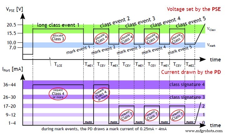
Figure 6: Class signatures and current levels
Autoclass Optimization
With autoclass, a PD that needs, for example, 65 W will identify itself as Class 8. The PSE will then allocate just over 66 W plus a small margin, instead of the default 90 W. Across an eight‑port switch, this can save up to 200 W, enhancing both safety and energy efficiency.
Phase 3 – Startup
The PSE limits inrush current to 450 mA for Classes 1–4 and 900 mA for Classes 5–8. Concurrently, the PD caps load current to 400 mA (Classes 1–6) or 800 mA (Classes 7–8) to protect both devices during power ramp‑up.
Phases 4 & 5 – Operation & Disconnect
During operation, the PD periodically draws a small current pulse (Maintain Power Signature, MPS) every 400 ms. If the PSE fails to receive an MPS, it disconnects power to prevent a stale connection.
Typical 802.3bt Powered Device Architecture
Figure 7 shows a typical PoE 2 PD circuit. AC‑coupled transformers feed the Ethernet interface, which drives a GreenBridge™ 2 rectifier—an efficient alternative to the conventional silicon diode bridge. The NCP1095 controller (ON Semiconductor®) handles detection, classification, inrush, and over‑current protection via dedicated pins. Autoclass support is enabled through pin 6, while pin 14 signals output readiness to downstream DC‑DC converters.
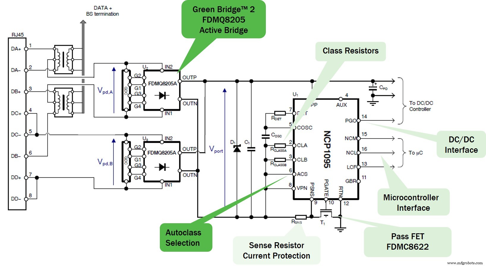
Figure 7: 802.3bt application diagram (source: ON Semiconductor)
ON Semiconductor also offers the NCP1096, which integrates the external FET and Rsense for a streamlined design.
Why Silicon Matters
Traditional fire‑safety devices—fuses, circuit breakers, earth wires—are passive and often react only after a fault has already occurred. PoE’s silicon‑based controls (classification, autoclass, inrush limiting, MPS) provide real‑time monitoring and automatic shutdown, dramatically reducing fire risk. For instance, an unresponsive device triggers an early disconnect, allowing IT staff to investigate before a fault escalates.
Moreover, silicon is far less costly than copper and can be programmed, offering a flexible, scalable, and safer power delivery solution than conventional wiring.
▶ This article originally appeared on Power Electronics News.
Bob Card is Americas Marketing Manager, Advanced Solutions Group at ON Semiconductor.
Related Contents:
- Powering smart buildings with Power over Ethernet
- 10 power management ICs for smart factories
- Tech advances behind Industry 4.0 bring new challenges for PCB manufacturing
- Using wired data connections to power demanding IoT devices
- How software‑configurable I/O is changing building automation
- PoE devices offer 90 W power sourcing
For more Embedded, subscribe to Embedded’s weekly email newsletter.
Embedded
- Power Sources: AC and DC Explained
- Bulldozer Technology: Design, Manufacturing, and Future Innovations
- How Next‑Gen PoE Powers IoT: 90 W Delivery for 5G and Beyond
- How to Choose the Right External AC/DC Power Supply for Your Product
- Microchip Launches PCIe 3.1 Ethernet Bridges with LPSS for Enhanced Power Efficiency
- Microchip Unveils 90W PoE Boosters for Legacy and IEEE Devices Without Changing Switches
- Silicon Labs Launches 90‑W PoE Portfolio for Next‑Gen Connectivity
- Master Lego Power Functions with Arduino & Bluetooth Control
- Wind Power: Converting Air Movement into Clean Electricity
- Mastering the Basics of OD Grinding: Essential Techniques and Insights