


Mastering Power Management with NXP i.MX RT500 Crossover MCUs
This article provides an introduction to microcontroller power management concepts. The NXP i.MX RT500 family of crossover MCUs will be used to illustrate how these concepts can be applied by embedded developers in real‑world applications.
Effective power management is a cornerstone of MCU design. Ignoring the power flows of CPU clocks, memory, and peripherals can impede the transition from design to a functioning product.
This guide covers MCU power modes, current consumption per mode, wake‑up latency, and how I/O pins and SRAM configuration influence overall power use. The NXP i.MX RT500 series exemplifies how power‑control features enable devices to operate with minimal power.
An Overview of the i.MX RT500 Crossover MCU
The i.MX RT500 is a dual‑core family built around the Arm® Cortex‑M33 core, clocked up to 200 MHz. It offers robust security with Arm TrustZone® and an eight‑region MPU, a CASPER crypto co‑processor for asymmetric algorithms, and a PowerQuad DSP accelerator. The integrated Cadence® Tensilica® Fusion F1 audio DSP, a dedicated 2‑D GPU, and multiple display interfaces make it ideal for secure, low‑power HMI, IoT, hearable, and smart consumer devices.
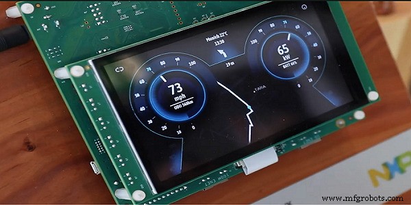
Figure 1. i.MX RT500 MCUs power modern embedded HMI applications that require fast and visually pleasing graphics and user interfaces. Image courtesy of NXP.
Complex mixed‑signal MCUs often integrate multiple on‑chip power supplies to enhance control and reduce noise cross‑talk. By separating core, I/O, analog, and always‑on rails, the i.MX RT500 allows the core to run at a lower voltage than the I/Os and to power‑down unused sections when idle.
Key power rails in the i.MX RT500 family include:
- VDDCORE – powers the main logic, DSP, peripherals, and memory. Adjustable between 0.6 V and 1.1 V, it can be managed by the internal PMU or an external PMIC. The required voltage depends on the pre‑divider core clock.
- VDD1V8 – a 1.8 V rail for on‑chip analog functions (excluding ADC/comparator) and the PMC module (bandgap, POR, temperature sensor, voltage detection). The VDD1V8_1 line supplies the on‑chip digital logic.
- VDD_AO1V8 – powers always‑on blocks such as the RTC, wake‑up timer, POR, RESET, LDO_ENABLE, PMIC_IRQ, PMIC_MODE0, and PMIC_MODE1 pins. This rail provides a wake source even when other rails are disabled, enabling recovery from deep power‑down.
- VDDIO – supplies the GPIO pins. VDDIO_0, VDDIO_1, VDDIO_2, and VDDIO_4 provide 1.8 V, while VDDIO_3 supports up to 3.6 V.
Investigating the Power Modes of the i.MX RT500 MCU
Modern MCUs offer a spectrum of operating modes that trade performance for power. In active mode, all blocks run at full speed. Sleep and power‑down modes progressively reduce clock frequencies, supply voltages, and power to unused sections.
The i.MX RT500’s PMC fine‑tunes power inputs, allowing lower VDDCORE voltages at reduced core frequencies or during deep sleep. It can even shut VDDCORE entirely in power‑down. While the PMC sets default voltages, developers can override them with an external PMIC via the PMIC pins.
The PMC supports five power modes, listed from highest to lowest power consumption:
- Active – all clocks to CPU, memory, and peripherals are enabled. The designer can configure each block’s power state via system registers or runtime APIs (see section 8.4.1.1.1 of the reference manual).
- Sleep – the CPU clock stops; peripherals can remain active and generate interrupts that wake the CPU. I/O pin levels stay static unless altered by an active peripheral. Only the CPU clock is disabled.
- Deep‑Sleep – CPU clocks are disabled, and most peripherals and analog blocks can be powered down unless explicitly retained. Software can keep key peripherals (USB, DMIC, SPI, I2C, USART, WWDT, RTC, uTick) active. Refer to section 8.4.1.3.1 for details.
- Deep Power‑Down – all clocks and supplies are disabled except the RTC. SRAM and registers, except those in the RTC, cannot retain data. All pins are tri‑stated.
- Full Deep Power‑Down – only VDD_AO18, VDD_AO1V8, and VDD_EAO remain powered. Wake‑up triggers a POR in the VDD1V8 and VDDCORE domains.
Exiting deep power‑down or full deep power‑down requires a full reset sequence. The MCU’s PMIC_MODE pins signal state changes to an external PMIC; in active mode the MCU controls these pins, while in reduced‑power modes the external PMIC takes over.
The Wake‑Up Process and Typical Wake‑Up Times
Wake‑up latency increases with deeper sleep modes due to supply stabilization and oscillator startup. Typical wake‑up times for the i.MX RT500 are:
- Sleep (200 MHz) – ~150 µs
- Deep‑Sleep – ~120 µs
- Full Deep Power‑Down – ~8.64 ms (reset sequence)
These figures apply under the test conditions specified in section 1.3.4 of the datasheet. The MCU always returns to active mode upon wake‑up.
Wake‑up sources vary by mode: in sleep, any peripheral interrupt, HWWAKE activity, or pin interrupt can wake the MCU; deep‑sleep supports a broader set (DMA, DMIC, SDIO, HASH‑AES, CASPER, PowerQuad, ADC, DSP, USB, ACMP, timers). In full deep power‑down, only the RTC and a system reset can wake the device.
Dynamic and Static Power Consumption of I/O Pins
I/O pins can significantly influence static and dynamic power. Internal pull‑resistors and voltage levels can draw continuous current, while switching activity adds dynamic consumption. MCU datasheets often omit I/O power figures because they are application‑dependent.
In deep power‑down, I/O pins default to a floating, high‑impedance state. Reset disables internal pull‑up/down and input buffers unless configured via the IOCON register.
Power Consumption in Sleep Mode and Deep‑Sleep Mode
Below are sample currents for the i.MX RT500 at various VDDCORE frequencies and voltages in active and sleep modes (DSP clock disabled). All values are measured at 25 °C with the internal LDO disabled and 128 KB of SRAM powered on.
| 12 MHz | 24 MHz | 48 MHz | 96 MHz | 192 MHz | |
| Active Mode (DSP no clock) |
1.62 mA |
2.5 mA |
4.33 mA |
9.35 mA |
20.73 mA |
| Sleep Mode (DSP no clock) |
1.8 mA |
4.78 mA |
5.78 mA |
7.78 mA |
9.66 mA |
In deep‑sleep, the typical current consumption of the power rails with 128 KB SRAM on and the internal LDO disabled is:
| Power Rail | Typical current consumption |
| VDD1V8 | 8.5 µA |
| VDDCORE | 42 µA |
| VDD_AO1V8 | 0.79 µA |
| All VDDIO rails combined | 5.61 µA |
| VDD_AO1V8 | 11.8 µA |
| REFP | 0.02 µA |
| USB1_VDD_3V3 | 1.10 µA |
Thus, deep‑sleep mode draws roughly 70 µA, while deep power‑down or full deep power‑down draws about 15 µA. Refer to tables 11 and 12 of the datasheet for exact test conditions.
SRAM Power Saving Considerations
On‑chip memory management is critical for power efficiency. Flash memory can be powered down without data loss, whereas SRAM requires explicit decisions about retention. The i.MX RT500 offers up to 5 MB of SRAM divided into 32 partitions. Each partition can be powered down or retained independently, enabling fine‑grained power trade‑offs.
Lower‑addressed SRAM partitions consume less current than higher ones due to their physical placement. Developers should prefer lower partitions when power savings are paramount.
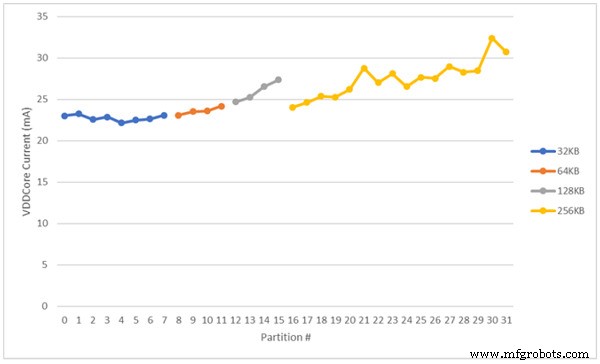
Figure 2. Developers should favor using the lower SRAM partitions over the higher ones when trying to reduce the overall power consumption of the MCU. Image courtesy of NXP.
For deeper insight, consult the i.MX RT500 Power Management application note and the reference manual, which detail various power‑saving techniques.
i.MX RT500 MCUs for Power Control and Power Management
Power preservation is essential for any embedded solution. The i.MX RT500 crossover MCU delivers comprehensive power‑control features that enable operation with minimal power while maintaining full functionality. In active mode, the designer can selectively enable or disable blocks via system registers or runtime APIs to tailor power usage to application needs.
For further information, NXP’s website hosts application notes, videos, and webinars that explore the i.MX RT500’s power‑management capabilities in depth.
Industry Articles are a form of content that allows industry partners to share useful news, messages, and technology with All About Circuits readers in a way editorial content is not well suited to. All Industry Articles are subject to strict editorial guidelines with the intention of offering readers useful news, technical expertise, or stories. The viewpoints and opinions expressed in Industry Articles are those of the partner and not necessarily those of All About Circuits or its writers.
Embedded
- Choosing the Right Device for Bluetooth Mesh: A Practical Guide to Hardware, Software, and App Requirements
- Raspberry Pi Unveils RP2040 MCU and $4 Pico Board
- Renesas Launches Low‑Power, High‑Performance Entry‑Level RA2E1 MCUs
- Renesas Launches 28 nm Automotive MCU with Virtualization‑Assisted Safety Features
- Renesas Expands Synergy Series with Low‑Power S5D3 MCUs Featuring Advanced Security
- ROHM Launches BD71850MWV PMIC for NXP i.MX 8M Nano Processors
- congatec Introduces SMARC 2.0 Module Powered by NXP i.MX 8M Mini Processor
- Renesas PMIC Reference Designs Streamline Power Management for Xilinx FPGAs
- Leveraging NXP i.MX RT500 for DSP-Enabled Smart Devices: Multi-Threading, XOS, and Cadence Fusion F1 Audio DSP
- Boost Manufacturing Efficiency: Validate Job Standards in Real Time with MachineMetrics