


Understanding Insertion Loss: Enhancing Filter Capacitor Performance
By Anthony Kenny, a seasoned RF engineer, this article explains how capacitors eliminate unwanted signals in analog and digital circuits. The effectiveness of a capacitor or a filtering network is quantified by insertion loss—a metric that captures the voltage attenuation introduced by the filter. Key determinants of insertion loss include the filter’s element configuration, source and load impedances, and the operating load current.
Filtering EMI in circuits
Electrical disturbances—both natural and man‑made—can significantly degrade electronic performance. These unwanted signals, collectively known as electromagnetic interference (EMI), are routinely suppressed with filtering networks. Common sources include lighting, storms, power lines, motors, ignition systems, radar transmitters, power amplifiers, computer clocks, and even cosmic radiation.
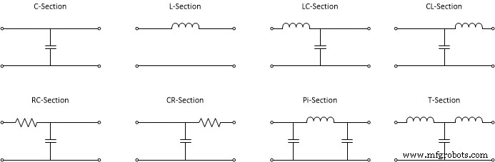
Element configuration
The topology of a filter dictates its performance. The simplest arrangement, a single‑feed‑through capacitor (C filter), offers modest attenuation. Adding inductive elements—forming L‑C, T, or π networks—substantially boosts attenuation. Each additional reactive element can improve insertion loss by roughly 20 dB per decade, a principle that guides the design of high‑performance EMI suppression circuits.
Featured image: Insertion Loss chart for different filter topologies; source: S.Nelson, Medium
Insertion loss characteristics of capacitors and circuits
Insertion loss is defined as the ratio of voltage before and after a filter. It is usually expressed in decibels (dB). The higher the dB value, the more effective the filter at attenuating unwanted energy.
Standard two‑terminal ceramic or electrolytic capacitors suffer from residual series inductance that limits their attenuation, especially at high frequencies. This inductance grows with electrode length and decreases with electrode width. Modifying the capacitor architecture—most notably by adding a third terminal—dramatically reduces series inductance and raises the self‑resonance frequency.
Feed‑through capacitors, engineered with a dedicated third terminal, exhibit superior insertion loss performance. They are widely used in EMI suppression and bypass applications. Popular designs include discoidal and tubular ceramic feed‑throughs, while plastic‑film variants are chosen for high‑reliability environments.
Insertion loss variation with frequency
An ideal capacitor’s insertion loss rises steadily with frequency. In practice, a real capacitor’s loss increases only up to its self‑resonance frequency, beyond which the loss falls as the component behaves inductively. Consequently, achieving low loss at high frequencies requires capacitors with a high self‑resonance and minimal residual inductance.
Factors that determine insertion loss performance
Beyond component type, insertion loss is governed by electrical configuration, load current, source impedance, load impedance, earthing impedance, dielectric material properties, and shielding integrity.
Configuration of components
Most practical filters combine capacitors and inductors. Single‑element filters provide ~20 dB/decade, two‑element filters ~40 dB/decade, and multi‑element networks can exceed 60 dB/decade. Designers select the topology that best matches the required attenuation, considering source and load impedance characteristics provided in datasheets.
Load current
High load currents can reduce insertion loss in inductive filters, especially when ferrite cores are used. The magnitude of this effect depends on the ferrite’s material properties.
Circuit impedances
Optimizing source and load impedances is essential to maximizing filter insertion loss. Selecting an appropriate topology that balances these impedances yields the best attenuation.
Conclusion
Capacitors remain a cornerstone of EMI mitigation in both analog and digital systems. While conventional two‑terminal capacitors offer limited insertion loss, three‑terminal feed‑through designs deliver superior performance. For applications demanding the highest attenuation, multi‑element L‑C, T, or π networks provide the most effective solution.
Internet of Things Technology
- Tantalum Capacitors: Key Characteristics & Applications
- Capacitor Charging & Discharging: A Hands‑On RC Circuit Experiment
- Insertion Loss & EMI Filter Performance: Expert Guide to Optimal Design
- How Equivalent Series Inductance (ESL) Impacts Capacitor Performance in High‑Speed Digital Circuits
- Edge Computing Demystified: Practical Use Cases in Transportation, Utilities, and Manufacturing
- Designing 5G Devices: Selecting the Ideal Performance Band for Your Application
- Requirements for Optimal IQ Modulation and Demodulation in Communication Links
- Enhancing Industrial Performance: Overcoming Monitoring Challenges with IoT & Analytics
- Leveraging IoT to Boost Performance in the Oil & Gas Industry
- Filter Capacitors Explained: Purpose, Types, and Applications