


Insertion Loss & EMI Filter Performance: Expert Guide to Optimal Design
In modern electronics, meeting stringent EMC requirements—such as the EU Directive and FCC standards—depends heavily on effective EMI filtering. This article, authored by Peter Mathews, dives deep into the critical concept of insertion loss and its impact on filter performance, offering a clear roadmap for selecting the right filter for any application.
Insertion Loss Fundamentals
Insertion loss represents the attenuation a signal experiences as it passes through a filter. It is expressed in decibels (dB) and varies with frequency. While laboratory data provides a useful benchmark, real‑world performance can shift based on circuit specifics. Therefore, insertion loss data is a foundational tool for engineers when narrowing down filter options.
Key Factors That Shape Insertion Loss
- Electrical configuration (capacitance–inductance topology)
- Source and load impedances
- Load current characteristics
- Ceramic dielectric material properties
- Earthing and grounding impedance
- Shielding integrity
Electrical Configuration
The optimal filter layout hinges on matching the source and load impedances. Insertion loss figures are typically published for a standard 50 Ω source and 50 Ω load. Deviations from this nominal impedance can either raise or lower the actual loss, so engineers must tailor the filter topology—whether it’s a simple C‑filter or a more complex L‑C‑L‑C‑L series—to the specific impedance scenario.
Common feedthrough filter topologies include:
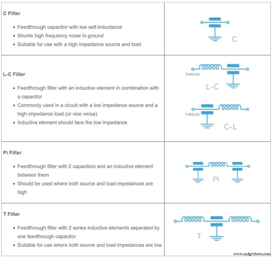
Multi‑Element Filters
These comprise more than three reactive elements—for example, L‑C‑L‑C‑L structures. Adding elements steepens the insertion‑loss curve, yielding sharper roll‑off and higher attenuation at target frequencies.
Impact of Load Current
Load current can alter insertion loss, especially in filters that incorporate inductive components. Ferrite inductors, for instance, may exhibit saturation at high currents, reducing their effectiveness. In extreme cases, the inductive benefit can vanish, and the filter behaves like a simple C‑filter, offering minimal attenuation.
Choosing the Right Filter
Selection criteria span electrical configuration, physical packaging, and dielectric material. The attenuation curve below illustrates how different physical implementations of the same electrical topology compare.
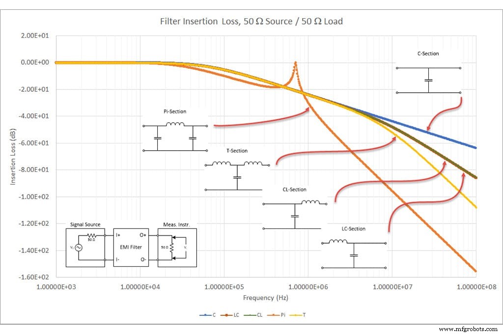
Notice that a compact chip filter offers the least high‑frequency attenuation. However, evaluating only one parameter can mislead design choices; a holistic view is essential.
Ceramic Dielectric Types
Different ceramic dielectrics exhibit distinct performance envelopes. As the dielectric constant rises—thereby increasing capacitance—the stability typically degrades. Variables such as temperature, applied voltage, frequency, and aging further influence the dielectric constant.
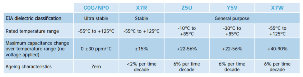
Three principal categories dominate EMI filter manufacturing:
Material parameters remain essentially unchanged across temperature, voltage, frequency, or time. Stability is quantified in parts per million, while dielectric constants are modest, ranging from 10 to 100.
X7R – StableOffers greater dielectric constants (≈2 000–4 000), enabling higher capacitance per unit volume compared to C0G/NP0. This class remains reliable under typical operating conditions. For voltage‑coefficient critical applications, Knowles Precision Devices provides BX (2 X 1) and BZ (2 C 1) variants.
Z5U/Y5V/X7W – General PurposeThese dielectrics have pronounced performance restrictions; applied voltage can markedly degrade their behavior. Knowles Precision Devices reserves its standard offerings for the higher‑performance C0G/NP0 and X7R classes.
Capacitance Spread and Insertion Loss
The capacitance of ceramic components varies with temperature, applied voltage, and aging. Consequently, the actual insertion loss can shift if capacitance falls outside its nominal range. Engineers should account for these variations during the selection and validation phases.
Featured image source: KnowlesCapacitors feedthrough
Conclusion
Insertion loss remains the cornerstone metric for assessing EMI filter effectiveness. By understanding how electrical configuration, load current, and dielectric material influence attenuation, designers can confidently choose filters that satisfy regulatory mandates while optimizing system performance.
Internet of Things Technology
- Mastering Cloud Application Monitoring: Insights for IT Leaders
- Understanding Insertion Loss: Enhancing Filter Capacitor Performance
- Assessing Precision of a Current‑Pump Circuit Across Resistor Tolerances and Automotive Temperature Ranges
- Designing 5G Devices: Selecting the Ideal Performance Band for Your Application
- Requirements for Optimal IQ Modulation and Demodulation in Communication Links
- Front‑Line Leadership & Key Performance Indicators for Maintenance Excellence
- Real-Time OEE Management: Boost Plant Performance & Cut Costs
- Benchmarking for Reliability & Performance Enhancement
- Enhancing Industrial Performance: Overcoming Monitoring Challenges with IoT & Analytics
- Leveraging IoT to Boost Performance in the Oil & Gas Industry