


Mastering the Pin Control Subsystem for Linux Device Drivers
 Editor’s Note: Embedded Linux is becoming the backbone of the Internet of Things, and device drivers are the bridge between applications and hardware. In “Linux Device Drivers Development,” author John Madieu offers a detailed, code‑rich guide to building these drivers.
This excerpt—Chapter 14 of the book—dives into pin control and GPIOs, a critical area for developers who need to interface custom hardware with the kernel. The first installment introduces the pin control subsystem.
Adapted from Linux Device Drivers Development, by John Madieu.
Chapter 14. Pin Control and GPIO Subsystem
By John Madieu
In embedded Linux, drivers almost always interact with GPIOs or configure pin multiplexing. A “pin” is the physical output line of a component, and many SoCs reuse the same pin for several functions. For example, the i.MX6QDL pin MX6QDL_PAD_SD3_DAT1 can serve as an SD data line, a UART RTS/CTS line, a FlexCAN Rx line, or a generic GPIO.
The process of selecting a pin’s function is called pin muxing, and the kernel component that orchestrates this is the pin controller. In the second part of this chapter we will explore the General Purpose Input/Output (GPIO) subsystem, a common pin function.
In this chapter you will:
- Walk through the pin control subsystem and learn how to declare pin‑control nodes in the Device Tree.
- Compare the legacy integer‑based GPIO API with the newer descriptor‑based interface.
- Handle GPIOs that are also used as interrupts.
- Explore sysfs interfaces dedicated to GPIO management.
Pin control subsystem
The pinctrl subsystem manages pin multiplexing and configuration. Devices that require a specific pin arrangement must describe that arrangement in the Device Tree. The pin‑controller driver parses these descriptions and programs the SoC’s I/O controller accordingly.
The subsystem offers:
- Pin multiplexing – reusing a single pin for multiple roles (UART TX, GPIO, HSI, etc.) on a per‑group or per‑pin basis.
- Pin configuration – setting electrical properties such as pull‑up/pull‑down, drive strength, debounce, and more.
Note that this book focuses on using the pin‑controller API; it does not cover writing a pin‑controller driver itself.
Pinctrl and the Device Tree
In the Device Tree, a pin‑controller node describes all available pin groups and functions. Each group is assigned an integer ID, optionally accompanied by a pinctrl-name that maps human‑readable names to IDs.
A device’s binding specifies the pin states it requires. Two properties link a device to pin states:
pinctrl-– a list of phandles pointing to pin configuration nodes. Multiple entries allow a device to be configured by several pin controllers or to combine multiple nodes for a single controller.pinctrl-name– a parallel list assigning names to each state ID. State 0 is usually nameddefaultand follows the standard list defined ininclude/linux/pinctrl/pinctrl-state.h.
Below is a typical Device Tree excerpt showing pin configuration for two devices:
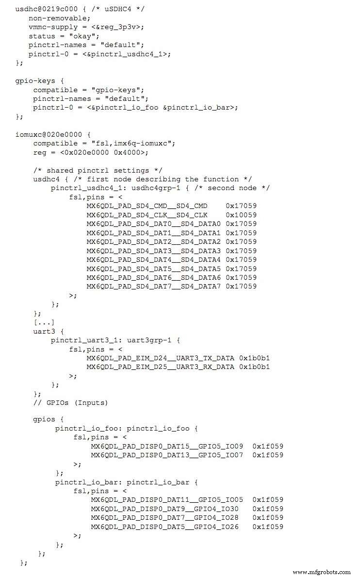
Each line follows the format <PIN_FUNCTION> <PIN_SETTING>:
MX6QDL_PAD_DISP0_DAT15__GPIO5_IO09  0x80000000
MX6QDL_PAD_EIM_D25__UART3_RX_DATA  0x1b0b1
The first token (MX6QDL_PAD_DISP0_DAT15__GPIO5_IO09) identifies the pin function; the second token (0x80000000) encodes configuration bits (pull‑up/down, drive strength, etc.). These macros are defined in architecture‑specific header files such as arch/arm/boot/dts/imx6q-pinfunc.h.
To program a pin state in driver code, follow these steps during initialization (typically in probe()):
struct pinctrl *pinctrl;

pinctrl = devm_pinctrl_get_select_default(&pdev->dev);
if (IS_ERR(pinctrl))
    dev_warn(&pdev->dev, "pins are not configured from the driver");
The helper pinctrl_get_select_default() automatically retrieves and applies the default state. If a device provides an init state, the core will apply that state before probe() and then revert to default afterward unless the driver changes it.
When finished, release the controller with pinctrl_put(pinctrl) or use the resource‑managed variant devm_pinctrl_put(pinctrl).
Here is a concrete example from the am335x-evm.dts file:
dcan1: d_can@481d0000 {
    status = "okay";
    pinctrl-names = "default";
    pinctrl-0 = <&d_can1_pins>;
};
In the matching driver:
pinctrl = devm_pinctrl_get_select_default(&pdev->dev);
if (IS_ERR(pinctrl))
    dev_warn(&pdev->dev, "pins are not configured from the driver");
By the time the driver’s probe() runs, the default pin configuration is already in place.
The next installment will cover the GPIO subsystem in detail.
Reprinted with permission from Packt Publishing. Copyright © 2017 Packt Publishing
John Madieu is an embedded Linux and kernel engineer based in Paris. He develops drivers and BSPs for clients in automation, transport, healthcare, energy, and defense. John works at EXPEMB, a pioneer in computer‑on‑module design, and is an active open‑source advocate who believes that knowledge sharing accelerates innovation.
Internet of Things Technology
- Robotics in the 21st Century: Distributed Systems, Telepresence, and Space Exploration
- Thyristor Technology: From SCR to TRIAC, GTO, and UJT
- The Rolling Pin: From Etruscan Origins to Modern Craftsmanship
- The Evolution and Craftsmanship of Modern Bowling Pins
- From Ancient Fibulae to Modern Manufacturing: The Safety Pin Explained
- Overcoming the Three Key Challenges in IoT Solution Development
- Why Industrial IoT Systems Are Prime Targets for Cyberattacks—and How to Secure Them
- Embedded Linux Device Drivers: Mastering Hardware Configuration
- Writing a Kernel Device Driver for Embedded Linux: A Practical Guide
- Embedded Linux Device Drivers: Runtime State Monitoring