


Top 5 Common STL File Issues That Can Sabotage Your 3D Print
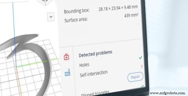
Above: AMFG’s AM Automation Software offers advanced tools for preparing and managing 3D printing workflows.
Converting a CAD design into an STL file is a critical step in additive manufacturing. The STL format translates the geometry into a mesh of triangles that a printer can interpret to build a physical object. When the export process introduces errors, the result can be failed prints, wasted material, and additional post‑processing time. Below are the five most common mistakes that arise during STL creation and how to avoid them.
What is an STL file?
An STL (stereolithography) file is the industry standard for 3D printing. It represents a model’s surface as a collection of triangular facets. Each triangle is defined by three vertices, edges that connect those vertices, and a normal vector that points outward. Because STL is an approximation of the original CAD model, it includes both interior and exterior surface data and must be a watertight mesh for reliable printing.
The top 5 STL file errors
A flawless STL mesh is closed, manifold, and free of overlapping geometry. The following errors are the most frequent culprits that prevent a part from printing correctly.
1. Holes or gaps in the mesh
Missing triangles create voids where adjacent facets fail to share two vertices. These gaps render the model non‑watertight, causing slicers to misinterpret the part’s topology and often abort the print. Ensuring that the STL is manifold—every edge belongs to exactly two triangles—eliminates this issue.
2. Flipped normals
Normals that point inward confuse slicers, which rely on outward-facing normals to determine where material should be deposited. A flipped normal can result in inverted geometries or failed layers. Verify normals before exporting or use automated tools to correct them.
3. Intersecting or overlapping triangles
Complex internal geometry can cause two surfaces to cross each other. While minor overlaps can be corrected manually, large intersections add unnecessary material and increase print time. Mesh repair utilities can detect and merge overlapping facets.
4. Bad edges
Edges that are not properly connected create non‑manifold geometry, leading to holes and erratic layer boundaries. Patching these edges with dedicated software ensures a clean, printable surface.
5. Noise shells
Extraneous shells—tiny, isolated triangular groups—do not contribute to the part’s structural integrity and inflate the file size. They often arise from inverted triangles and can be removed by normal correction or mesh simplification.
AMFG’s AM Automation Software can automatically detect and repair most of these errors, freeing you to focus on design and production.
Other considerations
Even after fixing the five core errors, a careful review of the part’s design remains essential.
• Wall thickness must balance strength and material savings. Walls that are too thin risk breaking during printing, while overly thick walls can generate internal stresses that cause cracking. AMFG’s software provides real‑time wall‑thickness analysis to help you fine‑tune your design.
• File size matters. Excessive triangle counts slow slicing and increase the risk of timeouts or crashes. If your STL contains an unnecessary number of facets, apply triangle reduction techniques to streamline the file without compromising geometry.
Discover how AMFG’s AM Automation Software can simplify your workflow—schedule a live demo today.
3D printing
- Shearing: A Fast, Clean, and Versatile Metal Cutting Solution
- Why Gas Springs Are the Smart Choice for Modern Applications
- Centrifugal Casting Explained: Process, Advantages, and Applications
- Top 10 Professional SLA 3D Printers for Precision & Reliability
- Key Factors to Consider Before Purchasing a Laser Marking Machine
- Essential Guide to CNC Production Machining: What You Need to Know
- 9 Essential Machine Learning Applications You Must Know
- When to Replace Your 3D Printer Nozzle: A Practical Guide
- Top 5 Most Powerful Metals Shaping Modern Engineering
- Essential PCB Inspection Techniques for Quality Assurance