


How to Install Heat‑Set Inserts for Strong, Reliable 3D Printed Threads
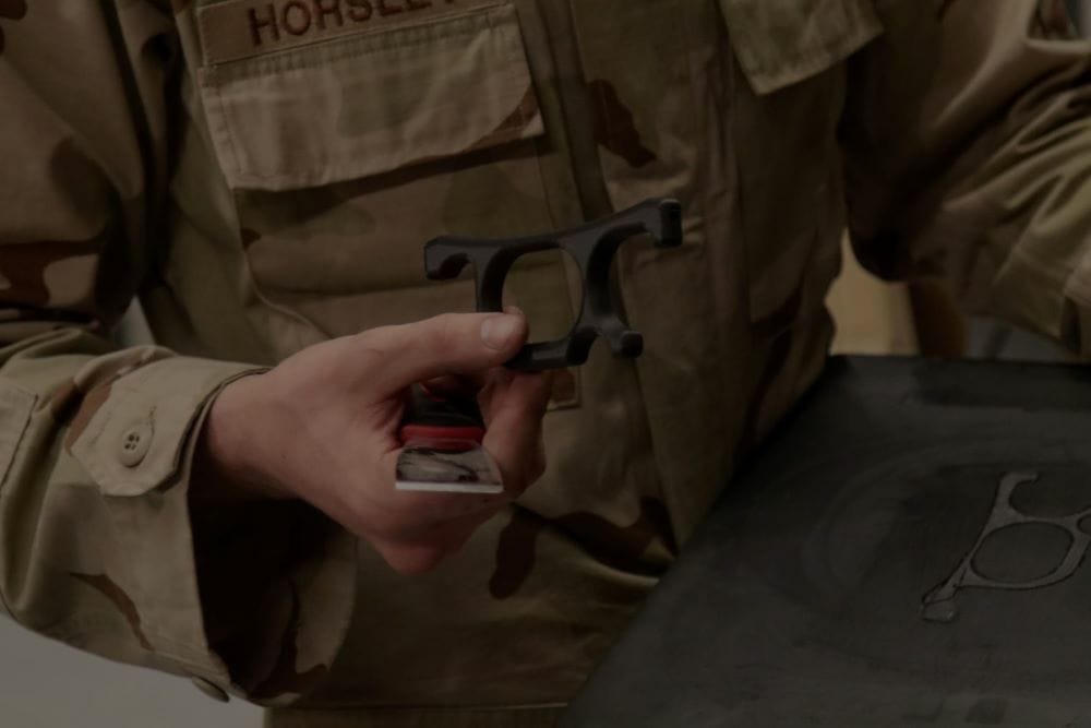
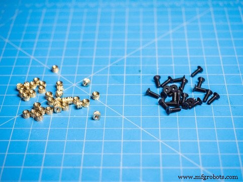
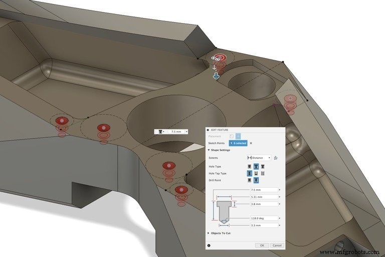
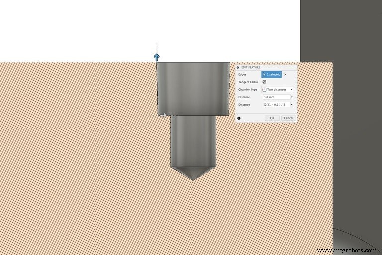
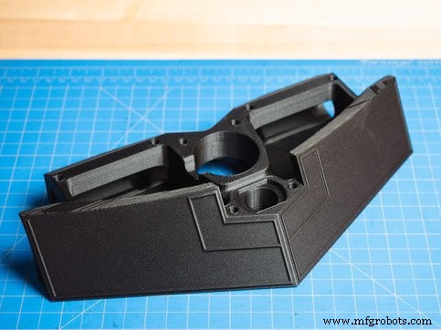
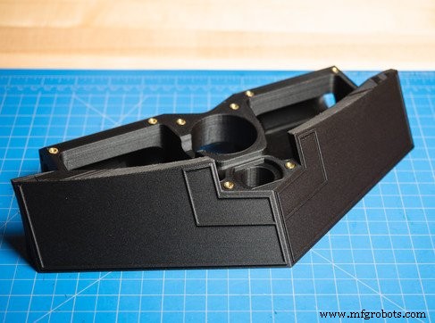
Threaded connectors, holes, and bolted joints are foundational to virtually every engineered part you manufacture. When working with 3D‑printed parts, the thread quality directly impacts assembly durability. Traditional plastic threads—either printed or hand‑tapped—are prone to stripping and wear, while metal threads deliver the strength and longevity required for high‑performance applications. Metal threaded inserts, typically brass with pre‑formed internal threads, provide a robust solution. Their knurled external surface engages the surrounding material, resisting pull‑out and torque‑out forces. For thermoplastic 3D printing, heat‑set inserts are the preferred choice. During installation, the polymer melts and reflows around the insert, creating a locally reinforced bond that dramatically improves pull‑out and torque ratings compared to other insert types. Read our latest customer success story about a major training base for the U.S. Army. Choose the hardware that will fasten the part. The insert size depends on the thickness of material surrounding the cavity; if less than 2 mm (0.078”) of material remains, opt for a smaller insert. Verify the vendor’s recommended cavity dimensions. In this example, an M3 insert is used with the following specifications: Use your CAD program’s sketch tool to mark the exact location of each hole. With the Hole tool, generate a counterbore that matches the insert’s major diameter (A) and recommended depth. Extend the hole beyond the counterbore base if a relief hole for screw clearance is needed. Apply a distance‑distance chamfer to the lower outside edge of the counterbore. Use the counterbore height as the first distance and ">(A‑B)/2" as the second distance to achieve the required minor taper diameter (B). Print the part once the design is finalized. Power the soldering iron and allow it to reach 650–750 °F (343–399 °C). This temperature range melts the thermoplastic without degrading the material. Place the insert centered on its cavity. Align the iron tip with the insert’s center and apply gentle pressure. As the insert heats, the plastic melts and flows, allowing the insert to sink into the cavity. Keep the iron in contact until the insert fully seats and the top of the part is flush with the insert’s head. For larger inserts, allow a slightly longer heating time. After all inserts are seated, let the part cool for a few minutes. This ensures the polymer fully sets around the insert. Use this time to adjust any inserts that did not seat correctly. While heat‑set inserts provide excellent pull‑out resistance, placing them on the opposite face of the part can further increase load capacity. When the insert is loaded, its taper engages the counterbore’s taper, distributing forces more evenly. Adding continuous fiber reinforcement around the cavity amplifies this effect by preventing wall deformation under load. Contact us for a free sample part to evaluate the strength and durability of our materials. Follow us on Facebook, Twitter, Instagram, and LinkedIn for the latest updates.Threaded Components in 3D Printing
U.S. Army Case Study
Designing for and Installing Heat‑Set Inserts
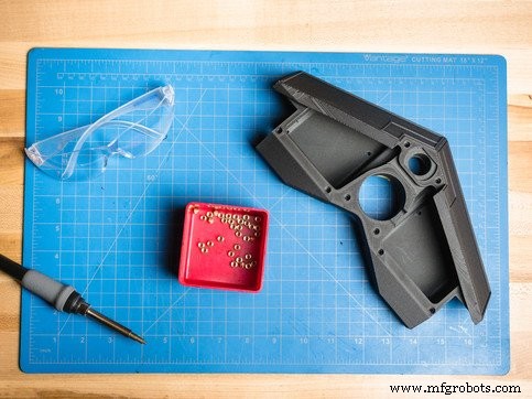
What You’ll Need
1. Select Bolt Size and Corresponding Insert
2. Sketch the Starting Point for Your Holes
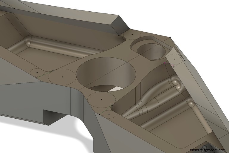
3. Create a Counterbored Hole
4. Chamfer the Inner Bore Edge
5. Print Your Part
6. Heat the Soldering Iron
7. Press Each Insert Into Its Cavity
8. Allow the Part to Cool
Enhancing Threaded Connection Strength
3D printing
- Heat Pump Technology: Design, Manufacturing, and Future Trends
- Mastering C# Using Statements: Imports, Aliases, and Static Directives
- Carl Calabria’s Expert Guide to Installing Inserts on the Mark One 3D Printer
- Polyurethane Insert Molding: Enhancing Fit and Function
- Selecting the Ideal Threading Insert for Reliable Metalwork
- Prevent & Fix Heat Creep in Your 3D Printer
- Heat vs. Ultrasonic Insert Molding: Choosing the Right Process for Your Production
- Threaded Inserts via Heat Staking & Ultrasonic Welding – Precision Solutions for Molded Parts
- Recycling Face Masks with Filastruder: A Sustainable Solution
- High-Strength 3D Printing Inserts for Durable, Precise Assemblies