


Master Toolpath Entry Control in Fusion 360 for Precision & Efficiency
The ability to control the entry points of toolpaths is a must for CAM programmers. See how Fusion 360 can help.
When machining components, it’s vitally important for the CAM programmer to have control over all aspects of the toolpath, to ensure quality, efficiency, and safety. The point at which your tool engages with the component is no different.
Entry points of toolpaths – scenarios
CAM programmers need the ability to control the entry point of toolpaths for many reasons. Let’s take a look at some potential scenarios:
Controlling where the witness mark on the component will be
If we’re leading into a vertical face with the side of an end mill, there’s going to be a mark where the tool has led in. Manufacturers often have strict tolerances to adhere to, dimensionally and from a surface finish standpoint. For instance, if your tool leads into a face that is governed by a surface finish tolerance, the mark left from the lead may jeopardize the function of the component.
Additionally, when creating components for the automotive industry, surfaces that are outward-facing have surface finish tolerances. For visual reasons, the same applies here. A witness mark left on an outward-facing surface deems the component unfit for use.
The process of removing witness marks is timely and expensive, requiring a skilled individual. Polishing marks out of components is a poorly controlled process. Leading with outcomes that vary depending on the skill of the individual. Even the most skilled polishers can damage the component deeming it unfit for use. It is this uncertain, timely, and expensive process that we can avoid by moving the entry positions of a toolpath.
Avoiding clamps, fixtures and staying within the machine limits
We often use our machine envelopes to the maximum capacity, so every millimeter counts. That said, it’s not uncommon for your clamps may be close to your component for maximum rigidity.
In this case, our toolpath may choose to lead in on a clamp. Without the ability to control the entry point, our only solution would be to move the clamp itself. Which is, as well all know, an undesirable choice. Likewise, with machine limits, our component may be on the limit. Thus, a lead-in on the area out of limits would violate this, not allowing us to run the NC code. Again, if we don’t have the option to move the entry point, our only option is to physically move the component more into the limits, if at all possible.
How Fusion 360 can help
The solution to these problems is to have complete control of where our tool enters and exits our stock. Within Fusion 360, there are a few ways we can do this.
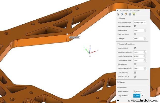
The first way is using the entry positions selection within the linking tab. Note that this option isn’t available for all toolpaths. The toolpaths that have this option are 2D adaptive, 2D pocket, 2D contour, 2D engrave, 2D chamfer, 2D slot, 3D adaptive, 3D pocket, 3D parallel, 3D scallop, 3D contour, 3D ramp, 3D pencil, 3D horizontal, 3D flow, swarf, and multi-axis contour.
In this example, we’re using 2D contour. In figure 1 you can see the original 2D contour with the default lead-in and out positions. The selection is being made to move the entry points via point selection on the component. You can see how the entry points have been moved as close as possible to the point we selected for entry positions.
Although this can be a good solution for many applications, there are alternative options in the Fusion 360 Machining Extension. This includes a new feature, Move Entry Positions in Fusion 360.
Move entry points – Fusion 360 Machining Extension
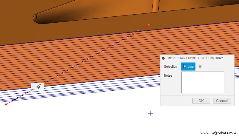
Move entry positions is in the modify tab with the other toolpath modifications. Once you select it, simply draw one or more lines through the closed sections of the toolpath (as seen below). When the lines intersect with the toolpath, Fusion 360 gives you visual feedback. This will show via black dots letting you know where the entry positions are being moved to. If the toolpath section is open, the toolpath sections are a different color. Thus letting you know the positions on this section of the toolpath that you cannot move.
Learn more about this feature in the video below:
Ready to give the Fusion 360 Machining Extension a try? Boost the core CAM capabilities of Fusion 360 with access to advanced 3-axis and 5-axis strategies, toolpath optimization, and process automation today.
Industrial Technology
- Fusion 360 Expands Multi‑Axis Toolpath Options for Superior Machining
- How Autodesk Fusion 360 Enables Efficient Concurrent Engineering
- Mill a Hemisphere in Fusion 360: A Complete, Professional Guide
- Fusion 360 CNC Guide: How to Machine a Chess Piece
- Mastering DXF Import in Fusion 360: Step‑by‑Step Guide
- Master Fusion 360’s Machine Builder: Build Custom Machines for Simulation
- Mastering Fusion 360's Machining Extension: Advanced Features for Precision Manufacturing
- Explore Haas CNC Tooling in Fusion 360's Comprehensive Library
- Master Toolpath Modifications in Fusion 360 Machining Extension
- Fusion 360's Generative Design: Bridging the Manufacturing Skills Gap