


Induction Heater Circuit Explained: Principles, Design, and Work Coil Applications
People use the induction heater circuit for heating conductive materials in a non-contact process. It’s also a device that uses a high-frequency magnetic field to heat ferromagnetic ceramics and metals. Besides, the induction heater is suitable for melting and forging steel as well as aluminum. Commercially, you can also use them for brazing, soldering, and heat treating.
An induction heater is particularly intriguing to build because it doesn’t need any induction heating element. Instead, the electronic device is similar to a stovetop which remains in temperature. This instructable explains the construction of induction heater circuits. The primary induction heater circuit is easy to build, plus it only uses some standard components.
So let’s get right into it.
1. Working principle of Induction Heater
According to Faraday’s law, learning the inductive heating process is essential—according to Faraday’s law of electromagnetic induction, switching the conductor in the electric field powers an alternating magnetic field. During the induction heater circuit process, the frequency moves faster than the electrons in the iron. Undoubtedly, it causes a reverse current which is the eddy current.
Through the development of the high eddy current, the iron also heats up. The principle also functions vice versa when the magnetic field changes in the conductor. The extreme heat is equal to the current 2x resistance of the iron. Because the loaded metal is iron, we’ll refer to the resistance R for the metal iron. So, the solid-state RF frequency power supply applies to the inductor coil and the materials you’ll heat.
Heat = I2 x R (Iron)
Resistivity of iron = 97 nΩm
Since the heat above equals the operating frequency, ordinary gate drive transformers do not work in high-frequency induction heating applications. The following process is the Joule heating principle. Here, after the current passes through a material, it generates magnetic materials. Furthermore, the simple designs of the induction heater circuit get set at the resonant frequency of the copper coil and circuit bank, which are similar to the tank circuit.
2. Elements of the Induction Heater Circuit
How can you construct an induction heater? Here we’ll discuss designing an induction coil and fast oscillating signal, including inducing current flows to make the metal hot. Like most devices, the induction heat circuit needs a circuit board and other active components.
2.1 Materials
- Impedance matching: The induction heating power supply capacity is similar to other previous generation devices. Because it has both AC and maximum voltage, the power impedance and load must be close to delivering a full power supply to the workpiece. Impedance matching control circuits work in induction heating to make the voltage, current and power values attain their highest limits. Besides, it’s useful in an electrical transformer.
- Power supply: The induction power supplies are an essential part of the induction heater system. The operating frequency range and power often rate them. Plus, there are several types of power supplies such as frequency multipliers, spark-gap converters and inverter voltage.
- Resonance tank: The Induction heater resonant tank is usually inductors and capacitors in parallel with a resonant frequency. What happens in the tank circuit is similar to a swinging pendulum. In the tank capacitor, the power supply provides energy that oscillates between the capacitor (electrostatic energy) and the inductor (electromagnetic energy). The energy transfer then becomes damped due to the losses in the inductor, load and capacitor. Furthermore, the capacitor bank provides the necessary capacitance to attain a resonant frequency with the same capacity as the power supply.

(resonance circuit)
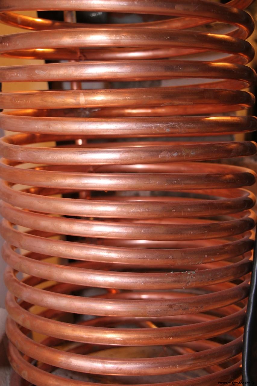
- Induction heater inductors
2.2 Induction Heater Circuit– The Induction Work Coil Design
The induction heater coil is a shaped copper tubing that applies power in several forms. The inductive current in the material is equal to the number of coil turns. Therefore, for the heating pattern’s efficiency and effectiveness, the primary coil’s design is essential.
It is also a conductive material that alternating current passes through to make a magnetic field. Conductive components and metal parts usually stay within, beside, or through the induction heat coil. Note that these materials never touch the ring, but they generate a magnetic induction in the metal to create heat.
Generally, induction coils function as water-cooled copper inductions. Depending on the application, there are also various coil shapes. But, the multi-turn helical coil is commonly used. With the ring, the heating pattern width is determined by the number of turns in the loop. So, single-turn locks are suitable for applications where the heating of silicon, material tip, or narrow band is essential.
Meanwhile, the multi-position helical coil heats many workpieces. Manufacturers further use the internal ring to heat internal bores, while the pancake coil heats only a side of the material.
(induction coil)
Induction Heater Circuit– Conditions you need to consider
- When you apply the coil on magnetic materials, it generates heat by both the hysteresis effect and eddy current.
- The position close to the connection of the separate coils has less magnetic flux density. So the ID center of the heating coil is never at the induction heat center.
- To increase the efficiency of the induction heat, you must reduce the distance between the pancake coil and load.
- If you position the part at the middle of the induction heating coil, it’s ideal you couple it alongside the magnetic wire or field. However, if it’s off-center, the load area nearer to the turns gets less heat loss.
- To decide the power capacity supply of the coil, take the convection, radiation and heat loss from conduction into consideration.
- The higher the critical frequency of the alternating current, the lower the heating penetration depth.
- Materials with higher resonance frequency are heated quickly.
(resonance tank circuit)
Coil Efficiency
Below is the coil efficiency formula:
Coil efficiency = energy efficiency from the bifilar coil transferred to the load/ energy transmitted to the coil
Induction Heater Circuit– Coil Modification According to the Application
Although the induction heat object needs uniform heating, it doesn’t have a constant profile in many applications. However, you can modify it using two methods. Firstly, decouple the curves where the helical coil has a larger cross-section. The other way is by increasing the winding inter-spacing at the places where the area cross-section is more significant.
A similar situation occurs when you heat flat surfaces with a big pancake coil. The other areas will receive less heat than the middle area. To prevent it, increase the space between the flat object and the coil surface by connecting a conical pattern to the pancake coil.
Induction Heater Circuit– Types of Heating Coils
Channel coils
Industries use the channel coil when the heating time is neither short nor long; But requires relatively low power levels. Several heating coils pass through it at a steady speed to attain maximum pressure when getting out of the device. In a bid to provide an entry and exit of the coils, their ends are often bent. Where an iron needs profile heating, industries use plate a flux concentrator alongside the multi-turn channel coils.
Double deformed coil
Manufacturers use the double deformed coil to attain uniform temperature, heating shaft tips, and brazing materials. The lock has tilted sides which help to reach uniform heating. To have a magnetic effect, you must pay attention to the path of both pancake coils in which the primary windings form.
(heating coil)
Split-return coil
It functions in applications like welding plastic, metal, and narrowband when doped with ferromagnetic ceramics. By using the split-return coil, you’ll induce a high current in the welding area, which will divide into two. So that way, the inductive heating process at the welding path is higher than other parts of the object.
Induction Heater Circuit– Lead Design for Induction Coils
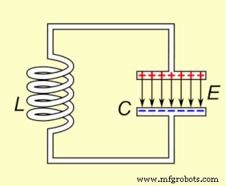
Although leads are short, they’re an essential element of the tank circuit and induction heat coil because they possess a finite inductance. The diagram below shows the circuit diagram of the heat station of a resonance circuit. C is the resonance capacitor in the heat station. Furthermore, L is lead which is the total inductance of the coil leads. V is the total input voltage from the induction power supply to the induction heater circuit work.
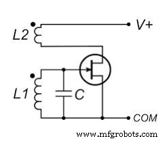
Source: https://commons.wikimedia.org/wiki/File:FET_Armstrong_oscillator.svg
Flux concentrator
The flux concentrator is a low electrical conductivity material with high permeability that works in the induction heater coil to amplify the magnetic flux or field on the heating load. The effect of the flux concentrator on the induction heater circuit is to improve heat efficiency on a low power level.
Induction Heater Circuit–Lead inductance deduction
Industries use the high inductance coils at a low frequency because the L- lead is smaller than the L-coil.
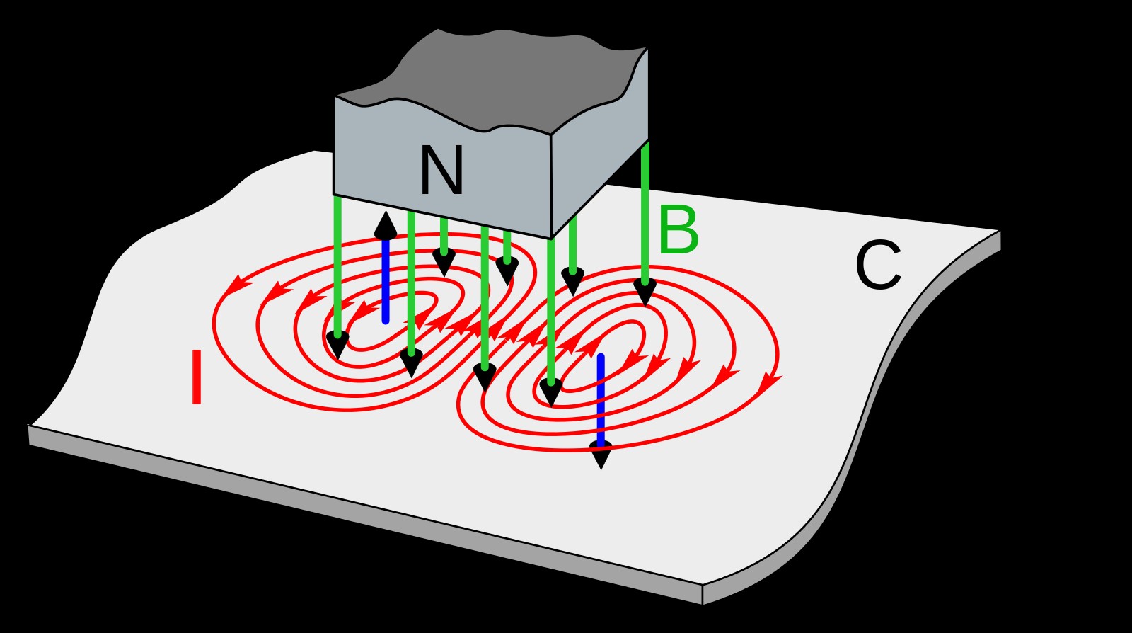
(eddy current in a magnetic field)
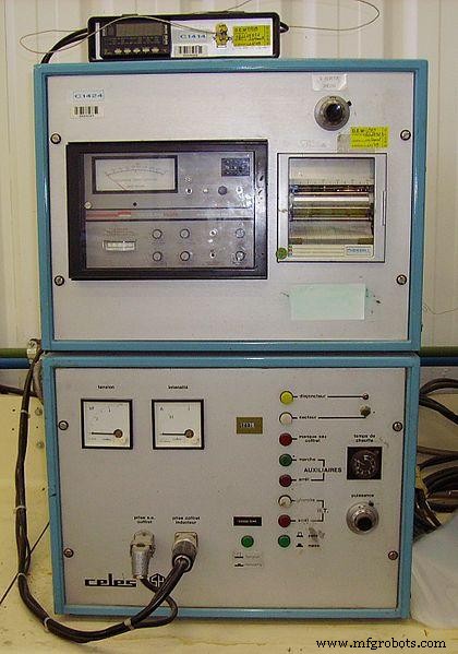
3. Example of Induction Heater Circuit Display
Below is the circuit diagram and setup of the induction heater circuit.
Conclusion
Compared to several electronic devices, induction heating appliances offer more efficiency, better control, and speed. However, the level of efficiency it attains depends on how well you construct and implement them.
The induction heater circuit provides you with a rapid, neat, and non-polluting method of the heating process. With the diagrams above, you should find the workings and designs of the tank circuit and induction coil easy to construct and test. You can always contact us at any time.
Industrial Technology
- Alarm Circuit Explained: Construction, Operation, and Working Principles
- Understanding LDO Circuits: Principles, Design Tips & Applications
- Passive Tone Control Circuits: Design, Applications, and Audio Benefits
- CD4049 CMOS Hex Inverter IC: Features, Applications & Circuit Diagram – Your Ultimate Guide
- Mastering Microcontrollers: Structure, Functionality, and Practical Applications
- How to Build an RGB LED Controller Circuit: Principles & DIY Guide
- Low-Voltage Cutoff Circuit: Design, Operation, and DIY Guide
- Micro Switches: Types, Working Principles, and Key Applications
- Reed Switch Circuit Explained: Principles, Applications, and DIY Build Guide
- CD4066 Quad Analog Switch: Key Features, Operation, and Practical Uses