


Piezoelectric Transducers Explained: Working Principles, Circuit Design, and Practical Applications
In everyday engineering and research, accurate measurement of physical parameters—such as mechanical stress, temperature, or pressure—is essential. A transducer is a device that transforms these physical inputs into proportional electrical outputs, typically voltage or current, enabling precise calibration and readout. Among the many transducer technologies, piezoelectric transducers stand out for their high sensitivity and wide range of applications. This article delves into the fundamentals, circuit design, and real‑world uses of piezoelectric transducers.
What Is a Piezoelectric Transducer?
A piezoelectric transducer is an electrical device that converts mechanical stress or strain into an electrical signal by exploiting the piezoelectric effect. When a piezoelectric material is subjected to mechanical force, it generates a voltage proportional to the applied stress.
The intrinsic piezoelectric property ensures that applying mechanical stress or strain induces an electric voltage proportional to that stress. By measuring this voltage with standard instrumentation, one can infer the magnitude of the applied mechanical load.
Types of Piezoelectric Materials
The following materials are commonly employed in piezoelectric transducers:
- Naturally occurring: Quartz, Rochelle salt, Topaz, Tourmaline-group minerals, silk, wood, enamel, bone, hair, rubber, dentin.
- Engineered ceramics and polymers: Polyvinylidene difluoride (PVDF), Barium titanate, Lead titanate, Lead zirconate titanate (PZT), Potassium niobate, Lithium niobate, Lithium tantalate, and various lead‑free piezoceramics.
Selecting a material for a transducer requires meeting criteria such as frequency stability, high output, environmental robustness, and the ability to be fabricated into diverse geometries without compromising performance. For example, quartz offers exceptional temperature stability but lower output, whereas Rochelle salt delivers high output yet is sensitive to humidity and temperature.
Principle of Operation
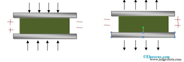
The piezoelectric effect occurs when mechanical stress causes a shift of ions within the crystal lattice, creating a separation of charge across the material’s surfaces. The polarity of the generated charge depends on the direction of the applied force, whether compressive or tensile.
Mathematical Relationship
The orientation of the crystal influences the voltage output. A crystal can be configured in a longitudinal or transverse arrangement.
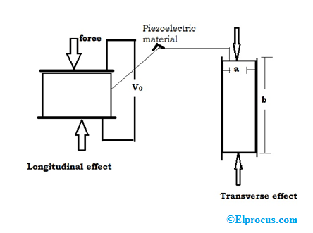
Longitudinal effect: Q = F × d where F is the applied force and d is the piezoelectric coefficient (for quartz, d ≈ 2.3 × 10⁻¹² C/N).
Transverse effect: Q = F × d × (b/a) with b/a representing the width-to-length ratio. When b/a > 1, the transverse configuration yields a larger charge.
Typical Circuit Configuration
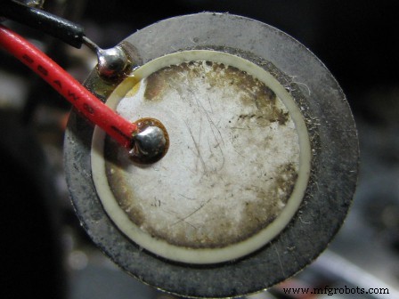
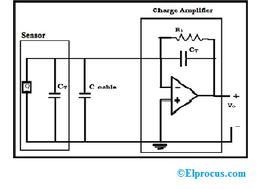
A basic piezoelectric transducer circuit incorporates a quartz sensor coated with a thin silver layer to generate voltage under stress. The generated charge is captured by a charge amplifier, which preserves the signal without dissipating it. A high‑resistance resistor (R1) limits current, and the lead capacitance is minimized by placing the amplifier close to the sensor.
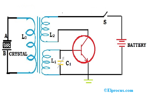
Ultrasonic Piezoelectric Transducer
An ultrasonic transducer leverages the converse piezoelectric effect: applying an electric field causes the crystal to deform, producing mechanical vibrations at ultrasonic frequencies. The circuit typically includes a transformer (primary L3) coupled to a high‑frequency oscillator and a secondary (L1, L2) that drives the quartz between two electrodes (A and B). When the oscillator’s frequency matches the crystal’s natural frequency, resonance amplifies the vibration, generating high‑amplitude longitudinal ultrasonic waves.
Applications
- Surface‑roughness measurement and vibration pickup.
- Seismographs and rocket vibration sensors.
- Strain gauges for force and stress monitoring.
- Automotive diagnostics for engine detonation detection.
- Medical ultrasound imaging.
Advantages and Limitations
Advantages
- Self‑powered via the piezoelectric effect, eliminating the need for external supply.
- Excellent high‑frequency response, ideal for dynamic sensing.
Limitations
- Susceptible to temperature and humidity variations.
- Inherently unsuitable for static pressure measurement.
In summary, piezoelectric transducers offer a robust solution for dynamic measurement across diverse industries. Have you implemented a piezoelectric transducer in your projects? Share your experience and insights.
Sensor
- How Distance Sensors Work and Their Key Applications
- Understanding the AD8232 ECG Sensor: Functionality and Applications
- HC‑SR04 Ultrasonic Sensor: How It Works and Key Applications
- VL53L0X Laser Distance Sensor: Pinout, Circuit, Specs & Practical Applications
- Fingerprint Sensor Technology: Working Principles, Applications, and Arduino Integration
- Vibration Sensors: Principles, Types, and Industrial Applications
- Piezoelectric Sensors: How They Work, Key Specs, and Arduino Integration
- Inductive Proximity Sensor: Circuit Design, Functionality, and Practical Applications
- Infrared (IR) Sensors: How They Work & Practical Circuit Diagrams
- CD4049 CMOS Hex Inverter IC: Features, Applications & Circuit Diagram – Your Ultimate Guide