


ACS712 Current Sensor: How It Works and Key Applications
What Is the ACS712 Current Sensor?
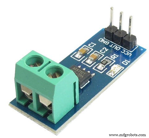
The ACS712 is a fully integrated, Hall‑effect based linear current sensor IC that provides isolated, accurate measurement of both AC and DC current. It features a 2.1 kV RMS isolation voltage and requires a simple 5 V supply, making it ideal for use in safety‑critical or industrial applications.
Available in 5 A, 20 A, and 30 A variants, the sensor delivers a calibrated analog output voltage that is proportional to the sensed current. This output can be read directly by a microcontroller’s ADC or used in analog control loops.
Working Principle
The sensor operates on the Hall‑effect principle: when current flows through the copper conduction path inside the IC, it creates a magnetic field. A Hall sensor located just beneath this path detects the magnetic field and converts it into a voltage proportional to the current magnitude.
The device uses indirect sensing, avoiding the need for a sense resistor and thereby eliminating power loss and thermal drift. Because the magnetic field is measured near the sensor, the ACS712 offers high accuracy and very low hysteresis.
Key pinout:
- Pin 1–4: Current conduction path (isolated from the rest of the circuit)
- Pin 5: Signal ground
- Pin 6: FILTER – an external capacitor can be connected here to set bandwidth
- Pin 7: Analog output (voltage proportional to current)
- Pin 8: Power supply (5 V)
Applications of the ACS712
Thanks to its isolation, low cost, and ease of integration, the ACS712 is used in a wide range of scenarios:
- Motor control circuits – real‑time current monitoring for torque regulation
- Switch‑mode power supplies – detecting load current and providing over‑current protection
- Automotive electronics – monitoring battery and alternator currents
- Home appliances – ensuring safe operation of high‑voltage devices (e.g., 230 V AC loads)
- Energy‑management systems – feeding accurate current data to a microcontroller for consumption tracking
- Peak‑detection and rectification stages in ADC front‑ends
- Fault‑tolerance circuits – using the sensor output to latch over‑current conditions
Because the output voltage is linear with current, it can be interfaced directly with an Arduino, STM32, ESP32, or any MCU that includes an ADC. A simple calibration curve (typically 185 mV/A for the 5 A variant) allows you to convert the measured voltage back to amperage with minimal processing.
Typical Use‑Case: Monitoring a 230 V AC Load
Connect the ACS712 in series with the load. The sensor’s isolated current path measures the actual line current without exposing the MCU to mains voltage. The analog output is fed to the MCU’s ADC, which then calculates the instantaneous and RMS current values for display or control purposes.
Sensor
- Blood Pressure Sensor: How It Works & Key Applications
- Voltage Sensors: How They Work & Key Applications in Modern Power Systems
- RVG Sensor: How It Works and Why It’s Transforming Dental Imaging
- Lambda (Oxygen) Sensor: Function, Operation, and Key Automotive Applications
- Image Sensors: Types, Operation, and Practical Applications
- Color Sensors: How They Work & Key Applications
- Compass Sensors: From Ancient Navigation to Modern Devices
- Fingerprint Sensor Technology: Working Principles, Applications, and Arduino Integration
- Vibration Sensors: Principles, Types, and Industrial Applications
- How Oxygen Sensors Work and Their Key Applications in Automotive and Industrial Systems