


Arduino-Powered Little Rover: Build Your Own Autonomous Robot
Components and supplies
 |
| × | 1 | |||
 |
| × | 1 | |||
 |
| × | 1 | |||
 |
| × | 1 | |||
| × | 2 | ||||
| × | 2 | ||||
 |
| × | 2 | |||
 |
| × | 1 | |||
| × | 1 | ||||
| × | 1 | ||||
| × | 1 |
Necessary tools and machines
 |
| |||
|
Apps and online services
 |
|
About this project
BackgroundMy nephew (9 y/o), and my niece (7 y/o) went totally nuts when they saw a video of an obstacle avoidance robot that I built a while ago.
Tutorial for that one will sadly never come as it predates my hard drive dying and me discovering the benefits of backups and DropBox, GitHub etc. :)
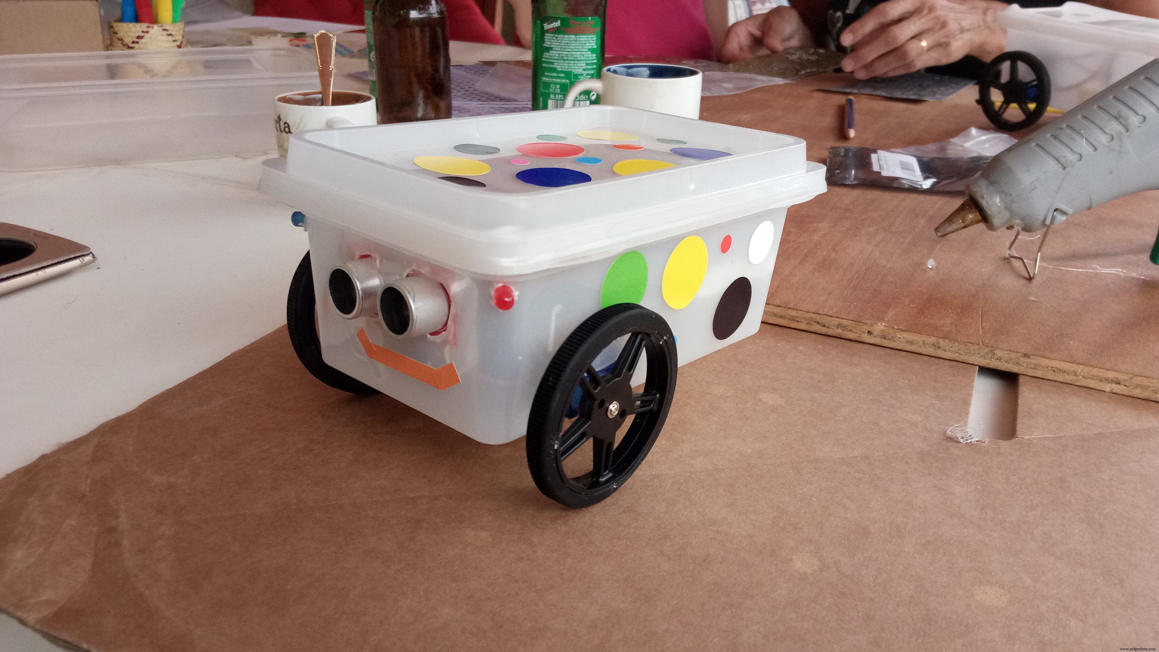
So I decided to see if I could come up with something that would be both (a little) educational and fun. I simplified my toy as much as I could and came up with this little rover.
The chassis is a box that originally contained crab-sticks. It turns out that the size was just perfect. (Thanks Dad for munching those by the crate-full :D ) A margarine container would probably also be the right size.
As a disclaimer, I will describe here how we built those robots and we let the kids do almost all the work themselves. I don't, by any means, recommend doing so. It's up to you as the responsible parents / guardians / aunt / uncle / babysitter... to determine whether each child in question can be trusted with the various tasks. Even though it wasn't really necessary, the children were made to wear protective goggles when working on the robots. The boxes we used were made of really soft plastic so I let my nephew and niece cut into those themselves after a briefing on the dangers of pointing the carpet knife towards themselves or their own limbs.To drill the holes for the LEDs, we used a small cordless electric screwdriver to limit the potential injuries.
I'm happy to report that the medical kit that I had on standby is still unused. :)
But to re-iterate, YOU are the adult!
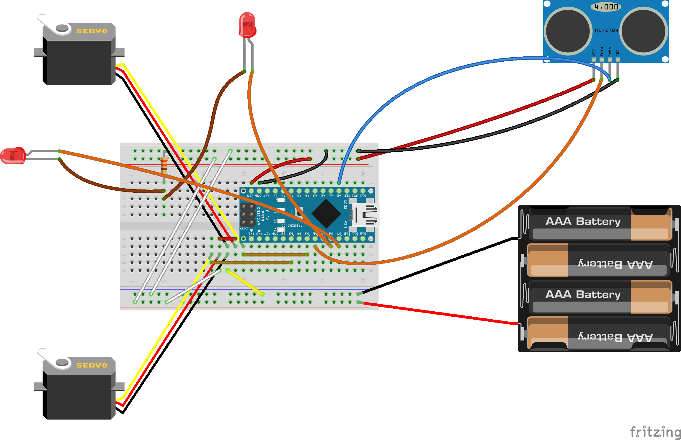
CircuitI made the circuit a little more complicated than I could have by connecting both servos the way I did.
For the kids... I keep saying that but the 'kids' included my sister (35 y/o) and my Mom (65 y/o), both of whom enjoyed the afternoon of Robots-and-Crafts as much as the actual children. :)
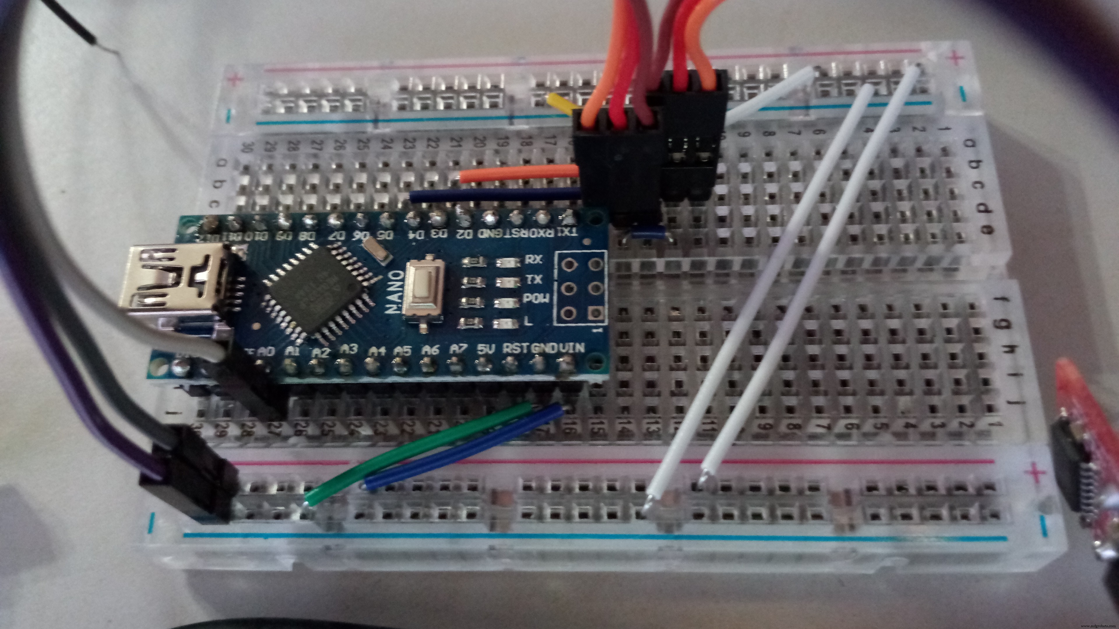
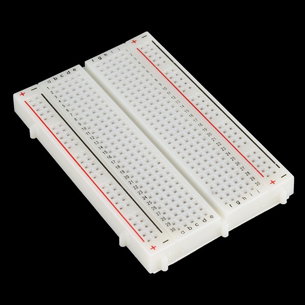
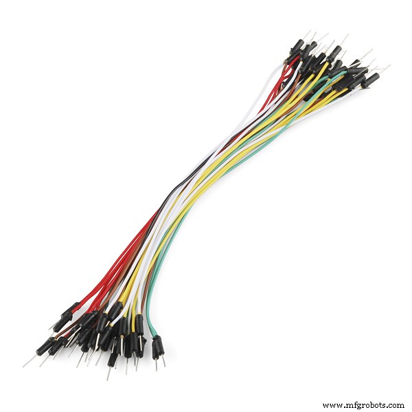
So for my audience, I printed the image on an A4 page trying to keep the scale of the breadboard 1:1 with the real world and gave them all jumper wires of the correct colour and length.
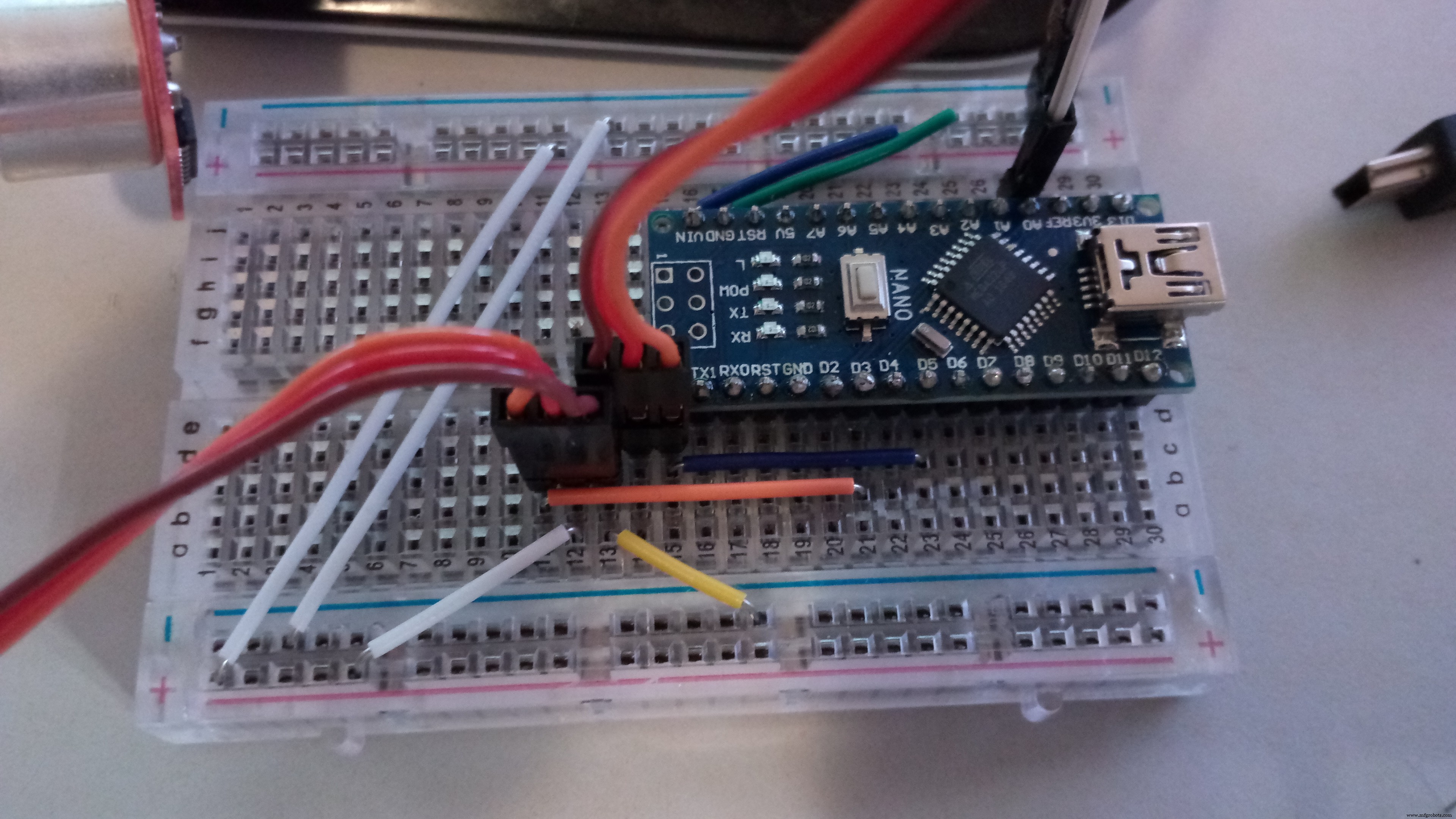
Once the circuit is assembled, simply load the program onto the Arduino. I included comments in the code to help you tweak the code a little, should you need to. If everything is connected properly, the servos should start turning and the LEDs will blink. And if you put your hand in front of the sensor, one servo servo will stop and the other spin in the other direction briefly.
All ready!
AssemblyIt's time to take you 'chassis' and make holes in it.
At the front, mark the position of your sensor and cut out the 'eye' holes.
On the side, measure nicely where you want the wheels to go and cut a hole in the side, at the edge of the bottom of the box, big enough for the servo to fit in but small enough so the mounting brackets don't go through.
Using a small drill bit, drill out 2 little holes for the LEDs.
On the bottom of the box, toward the back, screw in the caster wheel (or hot glue it).
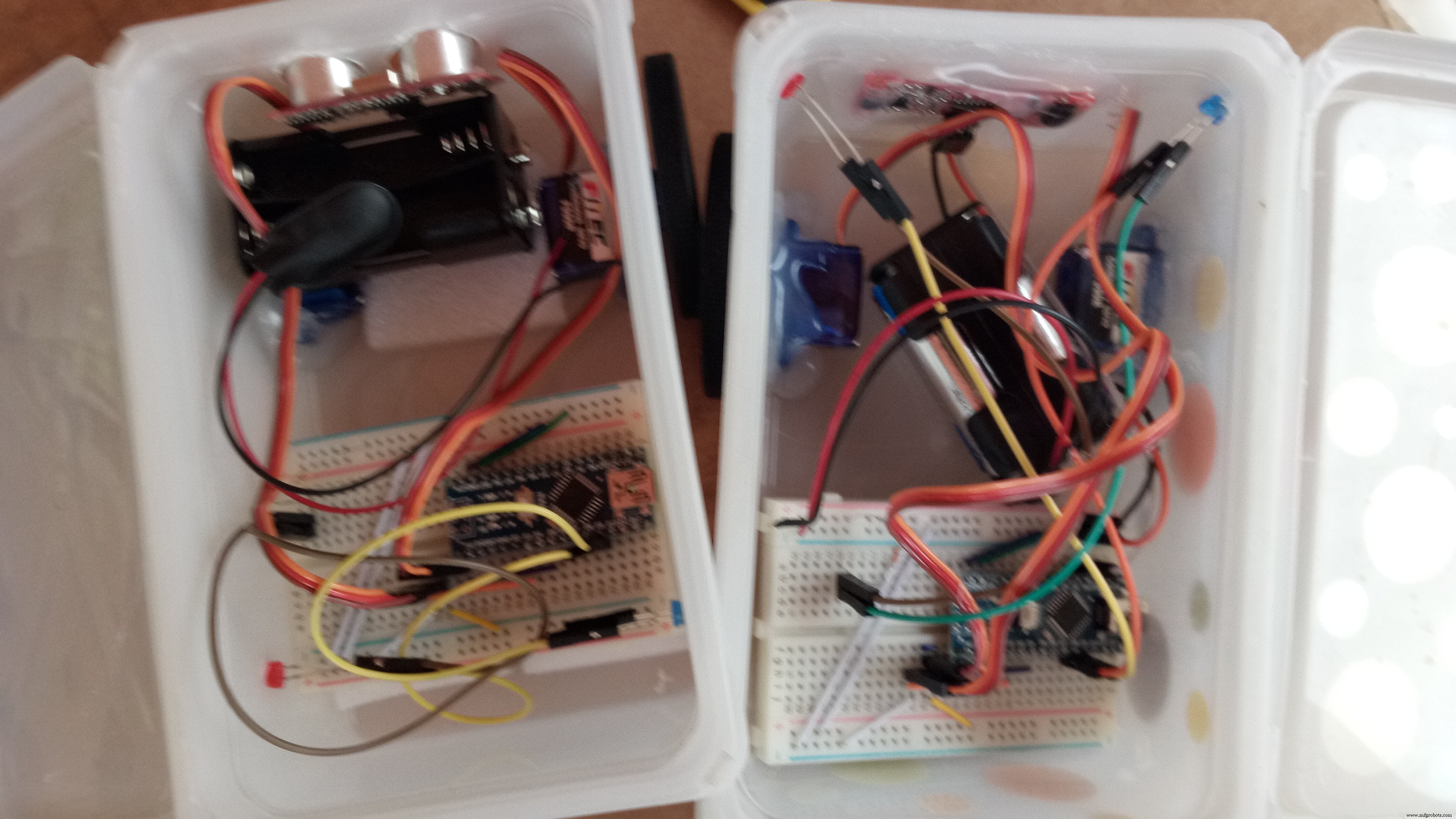
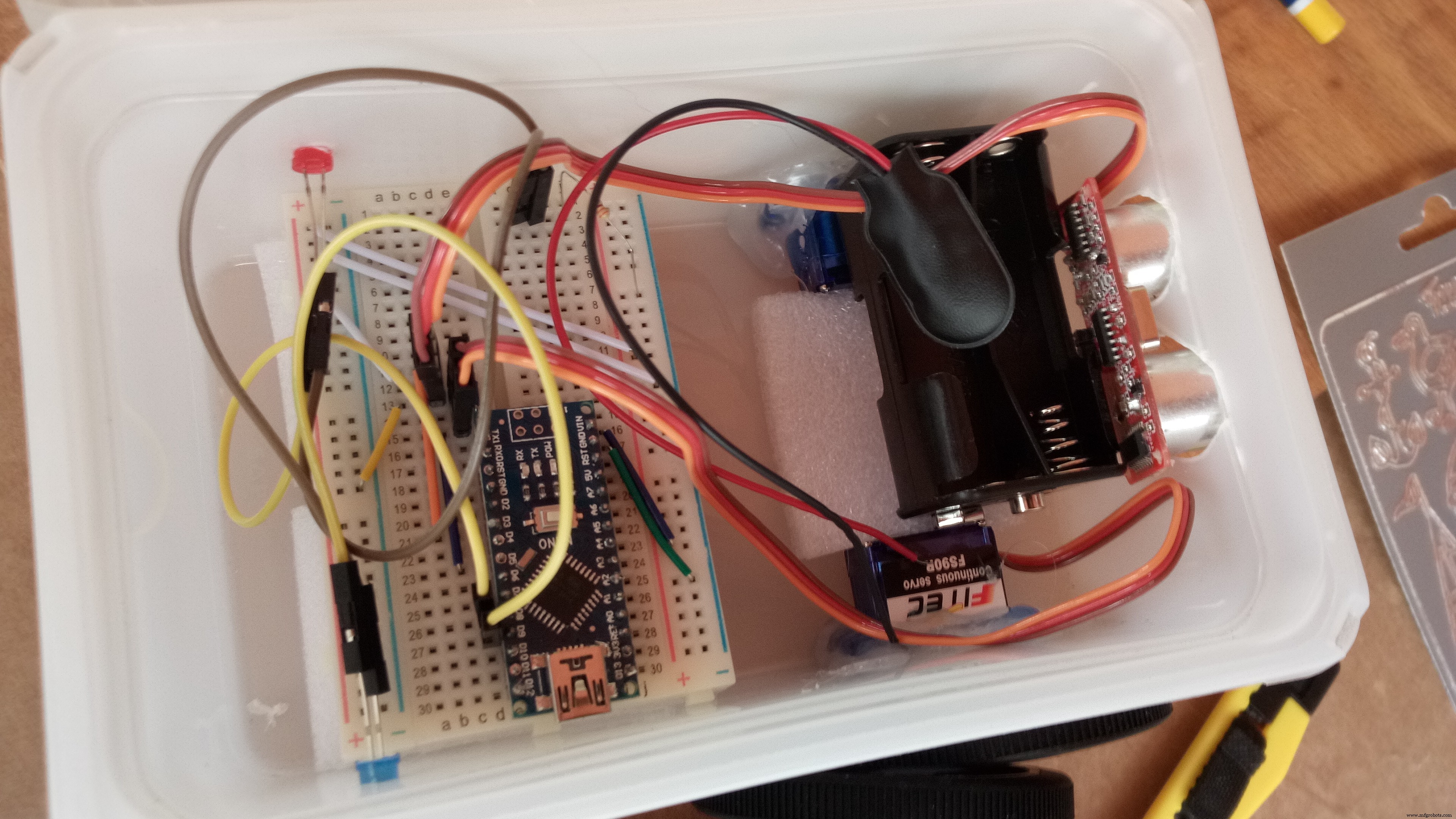
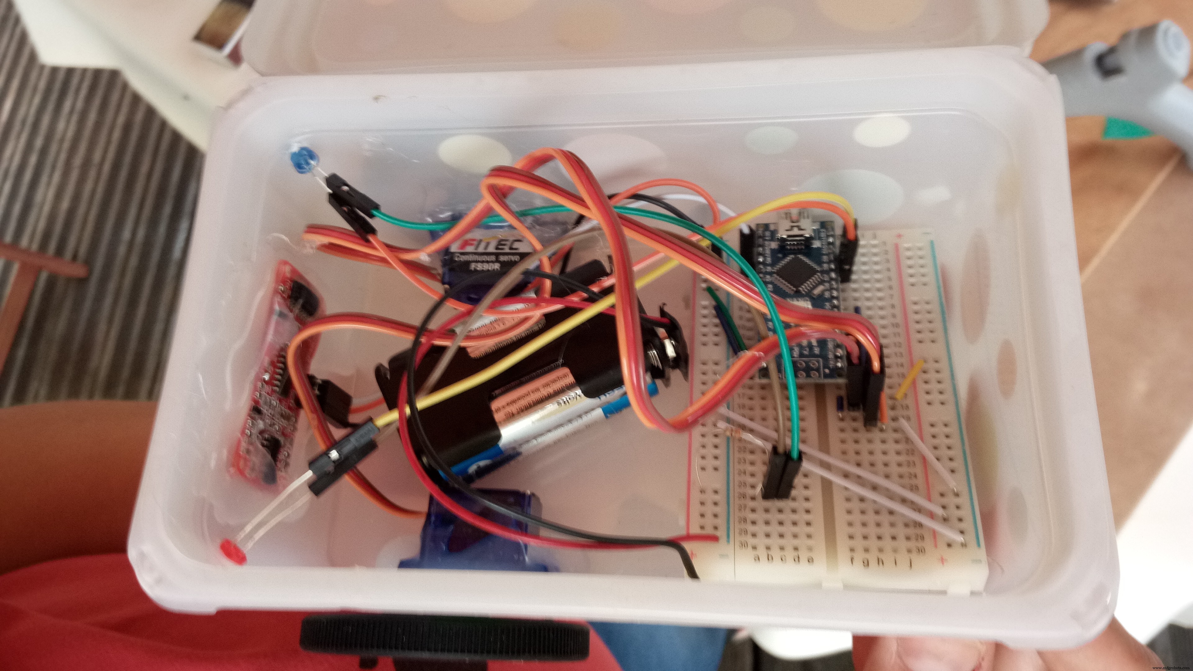
Now you are ready to put everything in the box, and hot glue the stuff in place.
Mount the wheels onto the servos once the glue has set.
Decorate the box! (And post pictures on them! That'd be awesome!)
Put in the batteries and watch the little rover move around the room randomly until the batteries run out. Or you get tired of the noise. Or the dog gets hold of it! :D
Code
- LittleRover
LittleRoverArduino
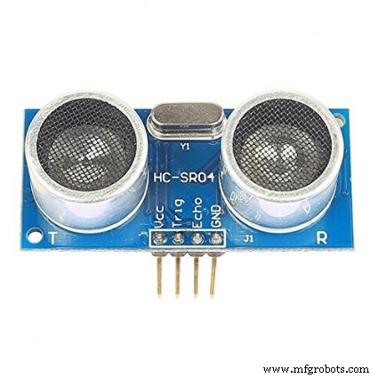
This is the version of the code for the 4 pins ultrasonic sensor#include <Servo.h>
/*
If you have a sensor with only 3 pins,
Uncomment line 6 and comment out line 7
*/
//int distanceR = A0; //Trigger pin
int distance = 6; //Trigger pin
int pingDelay = 10; //length of the pulse of the Ultra-sonic sensor
int distanceR = A0; //Echo pin
int led1 = 8, led2 = 9; //LEDs
Servo leftPower;
Servo rightPower;
unsigned long flashTime;
unsigned long nextSensorTime;
float obstacleDist = 0.0f;
void setup() {
//Serial.begin(115200);
leftPower.attach(3);
rightPower.attach(5);
leftPower.write(90);
rightPower.write(90);
pinMode(led1, OUTPUT);
pinMode(led2, OUTPUT);
delay(1000);
}
void loop() {
LEDs();
/*
This prevents the sensor from draining
the battery too quickly by limiting
the checks to 5 times per second
You can increase this number to check
less often but then it might run into
the wall...
*/
if(millis() - nextSensorTime > 200){
nextSensorTime = millis();
/*
I do 2 readings here because sometimes the sensor gets confused
and returns nothing...
*/
float reading1 = TakeReading();
delay(100);
float reading2 = TakeReading();
Serial.println(reading1);
Serial.println(reading2);
//Then we takes the biggest distance for obstacleDist
obstacleDist = reading1 >= reading2 ? reading1 : reading2;
//If the distance is less that 10cm, turn, otherwise, drive straight.
if(obstacleDist < 10.0f){
//Serial.println("turn");
turn();
}else{
//Serial.println("forward");
forward();
}
}
}
void LEDs(){
if(millis() - flashTime > 1000)
flashTime = millis();
if(millis() - flashTime < 500){
digitalWrite(led1, LOW);
digitalWrite(led2, HIGH);
}else if(millis() - flashTime > 500){
digitalWrite(led1, HIGH);
digitalWrite(led2, LOW);
}
}
void forward(){
/*
If you find that your robot is going backwards,
swap the 135 and the 45 around.
*/
leftPower.write(135);
rightPower.write(45);
}
void turn(){
/*
If you want your robot to turn the other way,
Uncomment lines 92-93 below and comment out 95-96
*/
//leftPower.write(90);
//rightPower.write(135);
leftPower.write(45);
rightPower.write(90);
delay(350);
}
float TakeReading(){
unsigned long echo = 0;
float result = 0.0f;
pinMode(distance, OUTPUT);
digitalWrite(distance, LOW);
delayMicroseconds(2);
digitalWrite(distance, HIGH);
delayMicroseconds(pingDelay);
digitalWrite(distance, LOW);
pinMode(distanceR, INPUT);
digitalWrite(distanceR, HIGH);
echo = pulseIn(distanceR,HIGH,38000);
result = echo/58.138;
return result;
}
Schematics
littlerover_87IypZOgwm.fzzManufacturing process
- Build a Windows IoT Core Rover with Raspberry Pi 2 – Beginner to Advanced Guide
- Build Your Own UFO Attack Game with Arduino UNO & MAX7219 Display
- 3D RGB Arduclock – Bluetooth LED Timepiece with Real‑Time Clock
- River Health Monitor: Arduino-Based Water Quality System
- Interactive Joystick Game with Arduino and LED Feedback
- Find Me: Smart Item Locator with Arduino and Bluetooth
- Build a Custom Arduino Joystick Steering Wheel for Gaming
- PhoneLocator: Securely Locate Your Phone Anywhere
- M1 Rover: Outdoor Autonomous Robot for Rough Terrain
- Ultrasonic Eyes: Interactive 8x8 LED Matrix Distance Sensor