


Smart Cube: The Next-Gen Home Control Hub
Components and supplies
 |
| × | 1 | |||
 |
| × | 5 | |||
 |
| × | 5 | |||
 |
| × | 1 | |||
| × | 1 | ||||
| × | 1 | ||||
| × | 1 | ||||
| × | 1 | ||||
| × | 1 | ||||
| × | 1 | ||||
 |
| × | 1 | |||
 |
| × | 1 | |||
 |
| × | 1 | |||
| × | 1 |
Necessary tools and machines
 |
| |||
 |
|
Apps and online services
 |
| |||
 |
|
About this project
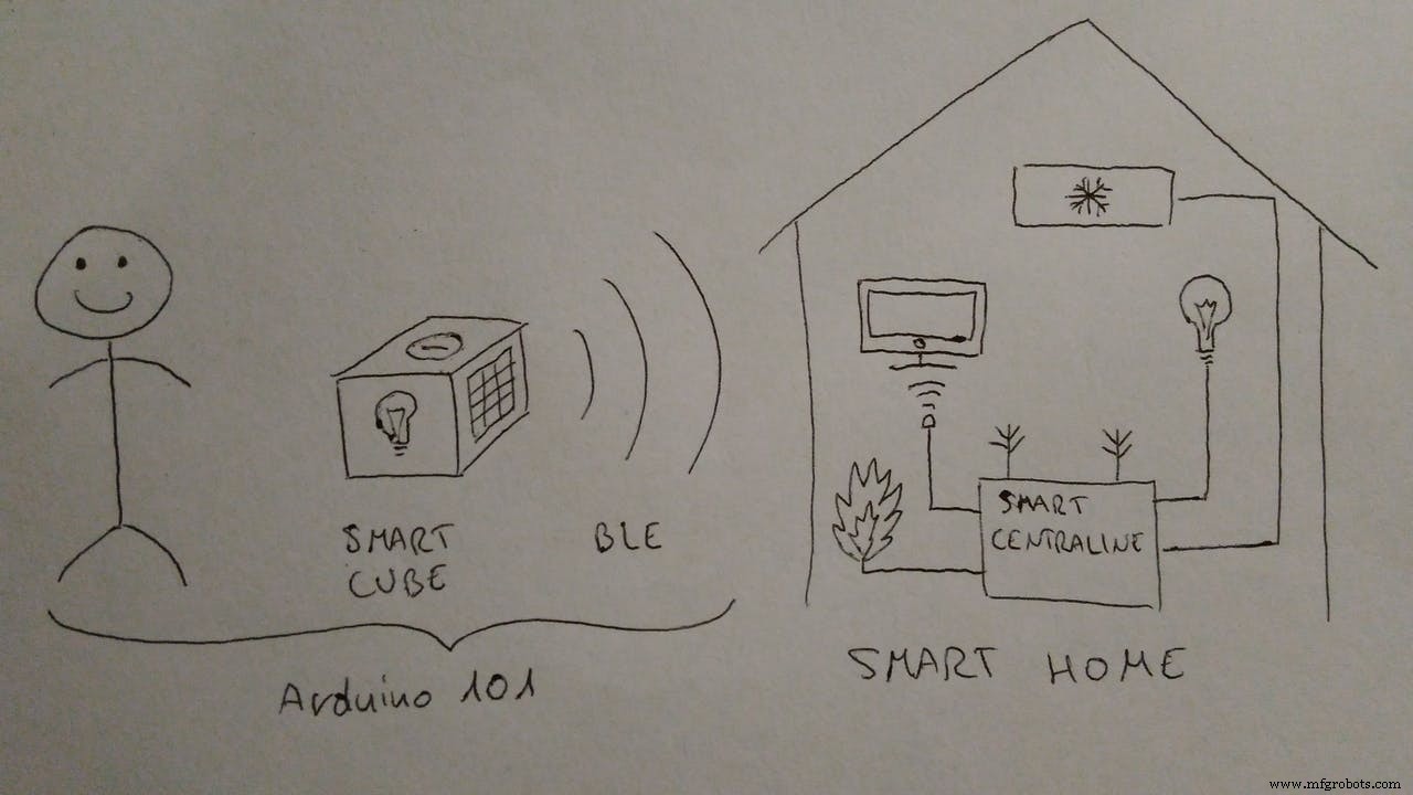
What is SMART CUBE?Smart Cube is a controller for your Smart Home devices.
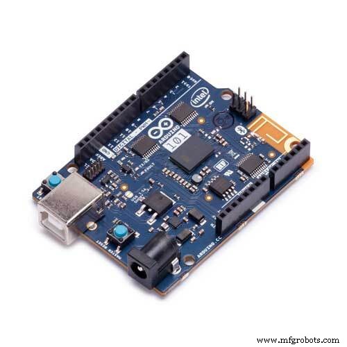
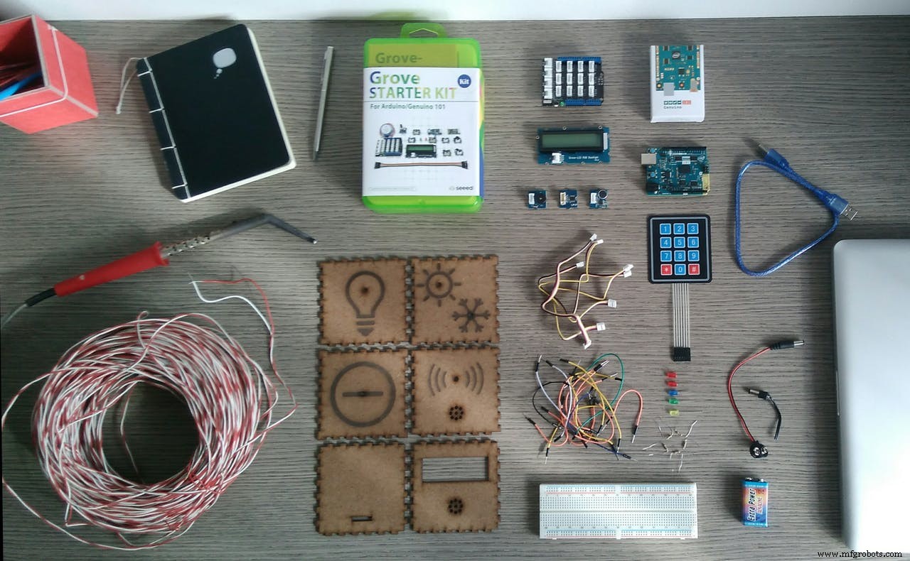
Nowadays managing in a smarter way all the devices in our homes is becoming an exigence. We need something simple and intuitive to use. Smart Cube could be a solution: it’s a portable device that contains an Arduino 101 board and some sensors that communicate with the appliances and the actuators in your Smart Home.
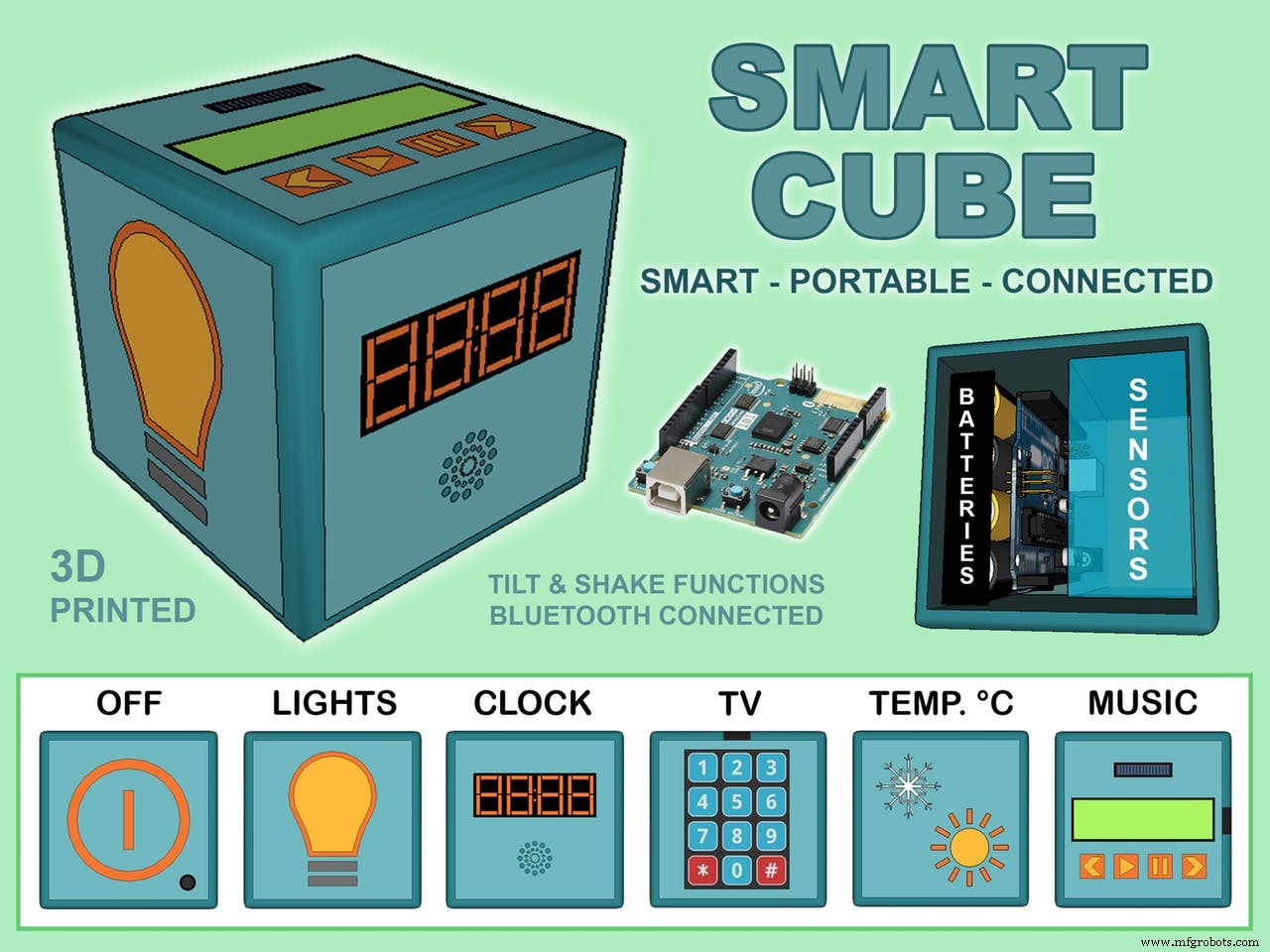
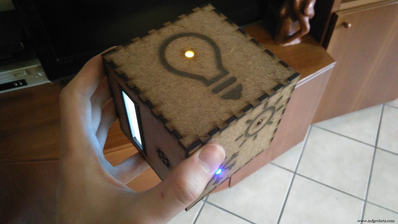
The innovation of this remote controller is related with the innovation of Arduino 101 board. It uses Bluetooth (BLE) to control lights, temperature and your tv and you can also synchronize it with your smartphone. But the major innovation is the way you interact with Smart Cube with your gesture using the gyroscope and the accelerometer. The cube has 6 faces and each one control a particular function. The function you want to use is detected thanks to the gyroscope that recognize the upper face. For example you can open the lights of the room in which you are just by positioning the cube with the “light face” in the upper position. If you want to switch off the light you just need to shake the cube.
If a face is UP and it doesn’t move for more than 2 seconds it is activated the related function. This delay is made so that you can have the time to rotate and interact with the cube to find the face you need without activating accidentally other functions. When you shake the cube for more than 2 seconds, the last activated function is closed.
This project aims to help you to build a smart controller. This device need a receiver (smart centraline in the picture) that interpret the data and manage the functions of your smart home. The main output of the cube is a BLE signal that could be used in many ways: for example you can connect the cube with a smartphone app (or make your own), or you can build a station with another Arduino that collect the BLE data and directly controls the appliances of your home. Because of the variety of cases, this part depends on your exigence. In this guide we will see how to build a smart cube and you'll learn how to personalize it.
The structure of the code is easy to personalize (we analyze the code later) so that you can decide which functions to control. These are the functions that I decided to control:
LIGHTS: This face in UP position open the lights of the room in which you are. If you shake the cube the lights switch off and a yellow led in this face is activated so you can find the cube in the darkness. The communication with your lamps is made by the BLE of the 101 board.
TEMPERATURE: This face UP activate (via BLE) the air conditioning if it’s hot or the heating if it’s cold. It detects the temperature using a thermal sensor and open a blue led if the conditioner is on (snow flake) or a red one if the heating is activated (sun).
TIMER: This face UP start a timer that you can see on the LCD display. There is a buzzer that work as an alarm when the countdown is finished. If you shake you stop the timer and you can see the remaining time. When the countdown ends the color of the LCD change from blue to red and the buzzer make three sounds.
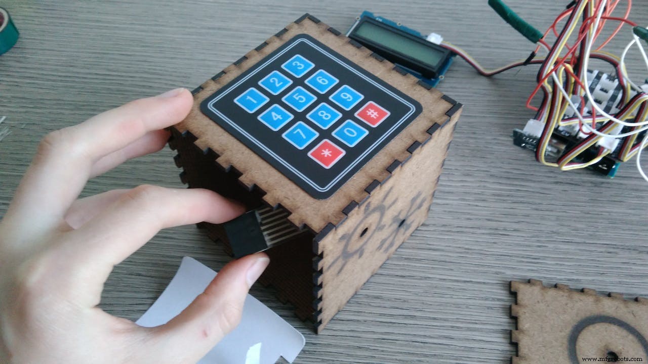
TV: This face UP open the TV. The cube become a remote controller for your TV. There is a button panel with numbers that is activated only if this face is UP so to avoid accidental touches. The number you push is send via BLE to the central controller that is connected to your TV. Shaking the cube you close the TV.
SOUND: This face UP activate a led whose brightness is based on the noise level of the room. The noise is detected thanks to a sound sensor. If you shake the cube you close this function. (If you want you can activate your personal function clapping your hands).
OFF face: If you don't shake the cube this face is like a neutral position in which nothing is changed. If you want to close everything position the cube with the OFF face UP and shake it. This gesture is like the home button on you smartphone that you press if you want to exit quickly. There is a red led so that you can find the cube if it’s dark.
Differences from the concept:The original plan was to use also IR communication to connect your TV directly to the cube. Because the Arduino 101 don't support (for now) the library that manage the IR signals I decided to send the information via BLE to a station that can manage this library (like Arduino UNO). Because of this problem I have removed the radio function (very similar to TV face), replacing it with a sound sensor face. This face could be used to recognize a loud noise (like hand clapping) to activate something. The biggest change is in the material of the cube. Initially I though to build it with a 3D printer but then I decided to use a laser cutter. In this way is easier to substitute a face if you want to change a function. For example you can remove the timer face and change it with a face that automatically fill your cat's bowl. Being modular you don't need to re-build the entire structure!
Follow this instructions to build your own smart cube. We'll start from the hardware, assembling the electronics components first and then the laser cut body of the cube made of MDF. After this operation I'll explain how the code works and how you can personalize it. After you have uploaded the code on your Arduino 101 you can download the app to see the BLE output of the cube or connect it directly with your smart home!
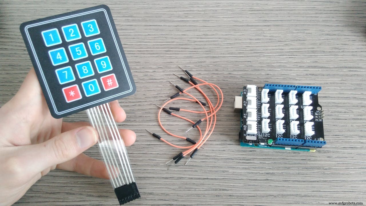
Let's start form your Arduino 101. This is the fritzing scheme to follow:
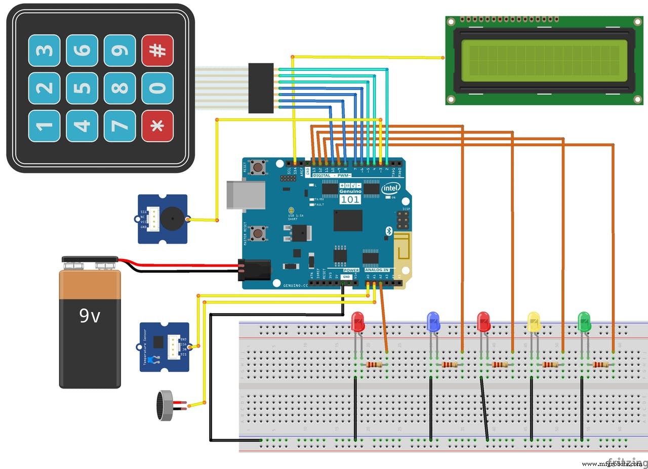
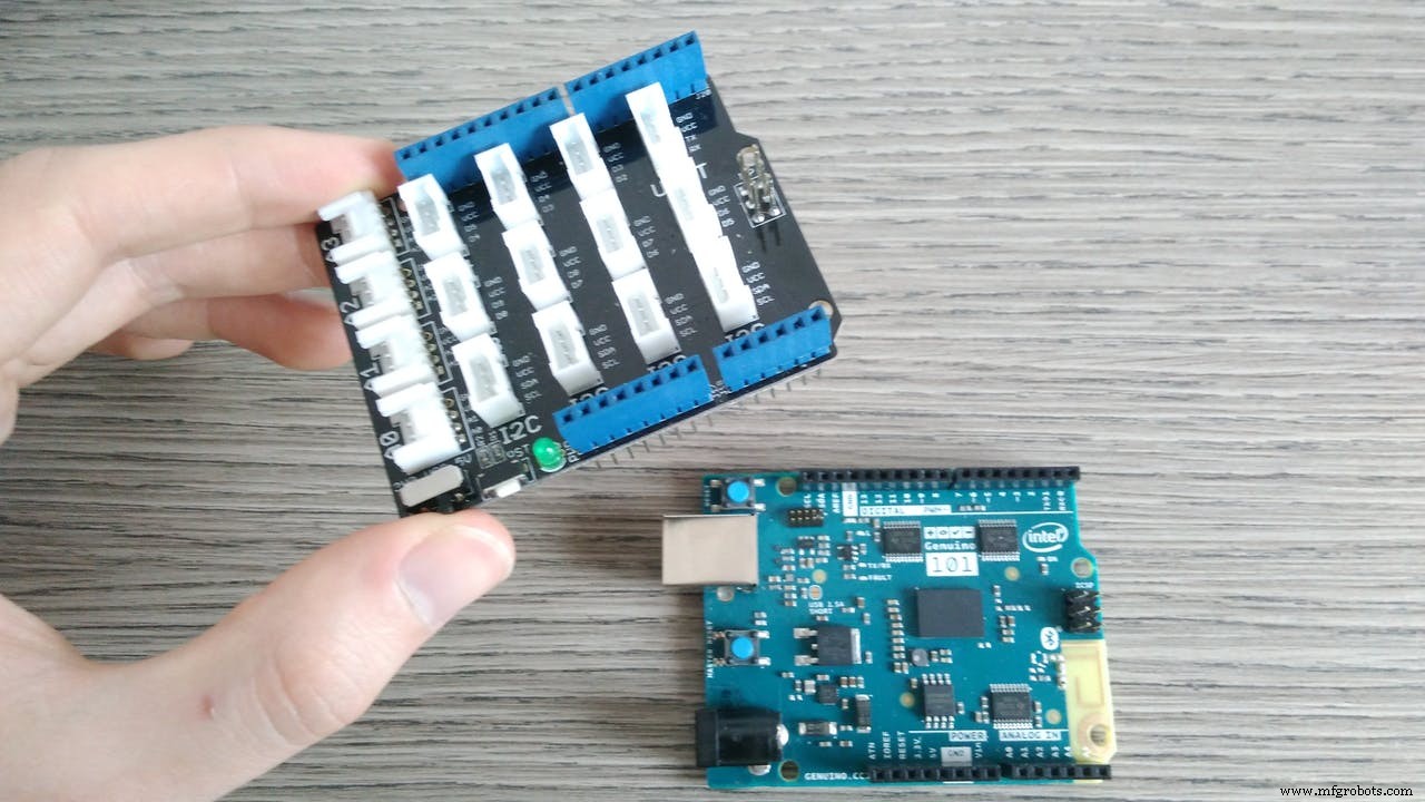
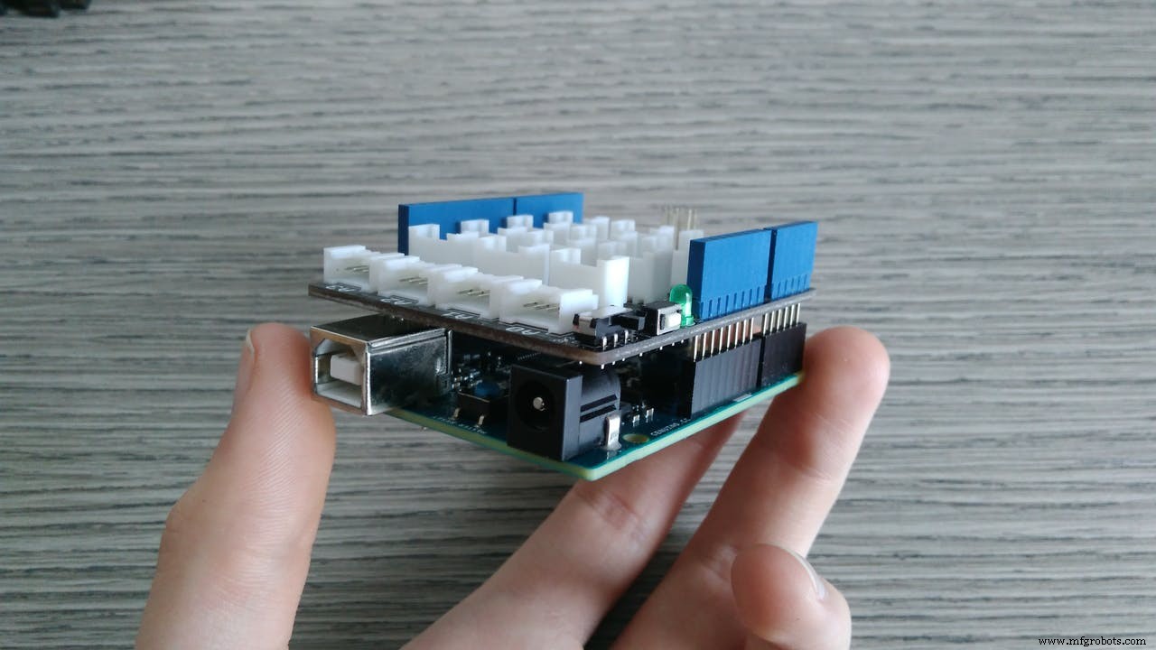
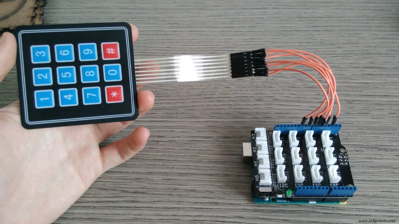
Mount the Grove base shield on your board and start with the connections.
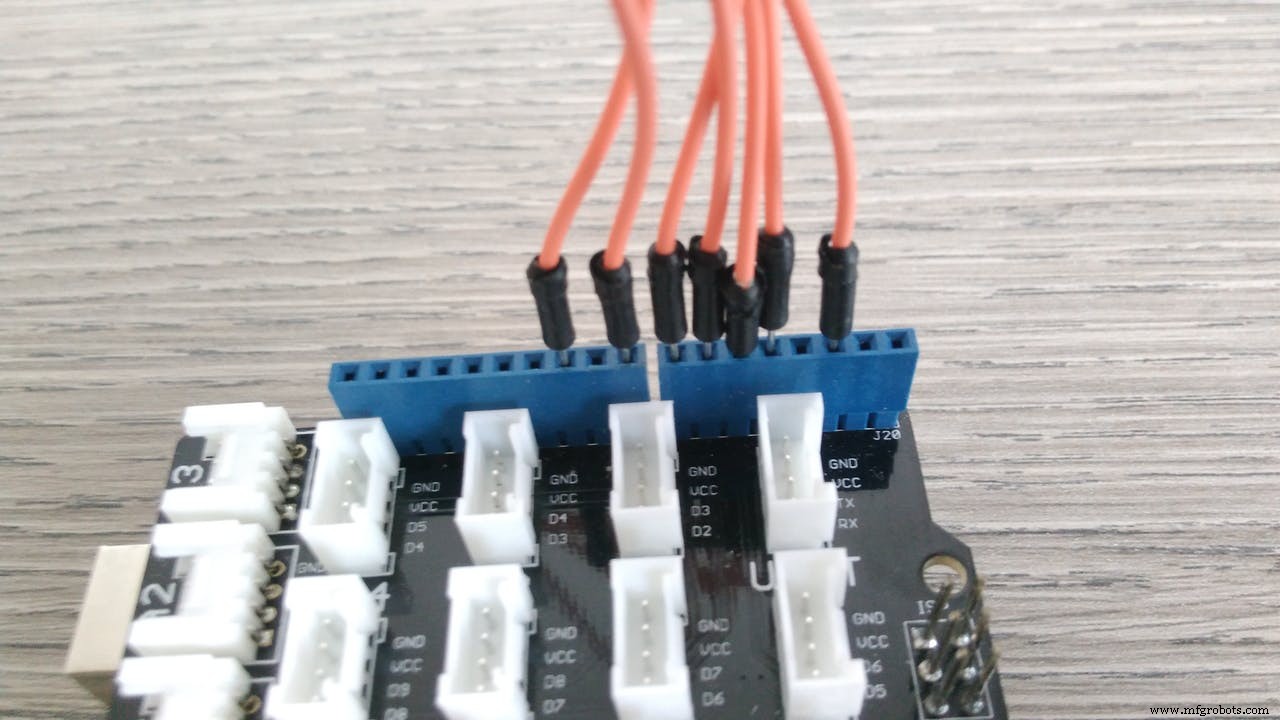
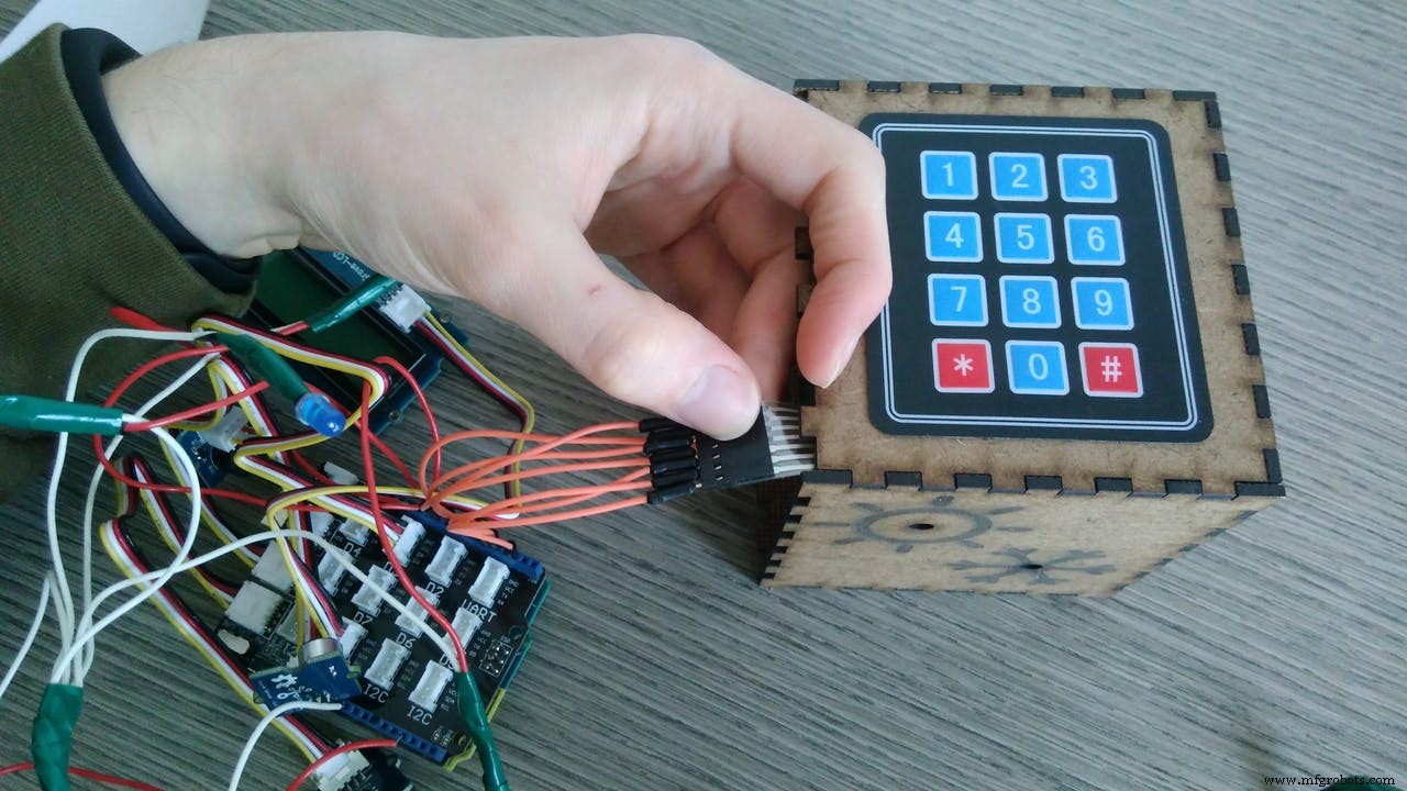
Keypad: you have to connect the wires in order to the pins: 10, 8, 7, 6, 5, 4, 2.
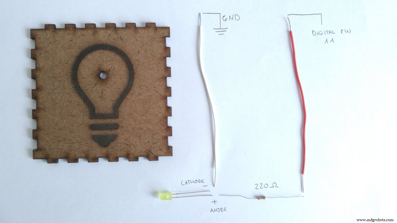
LED connections:
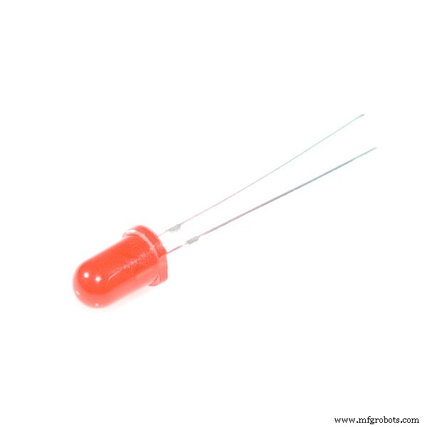
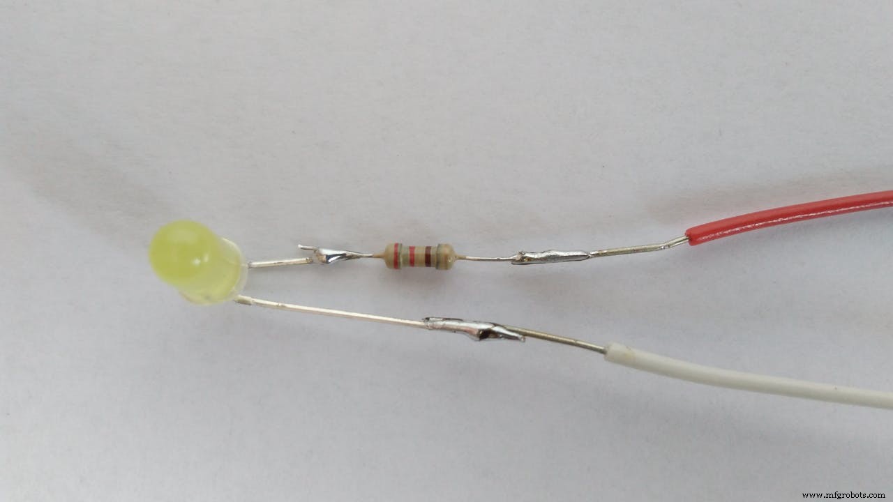
First of all we have to prepare the leds:
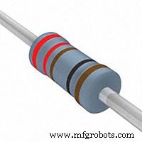
- connect the long leg of the led (anode) to a 220 ohm resistance and then to a red wire (this is the cable to connect to the pin)
- connect the short leg (cathode) to a white wire (this will go to the gnd)
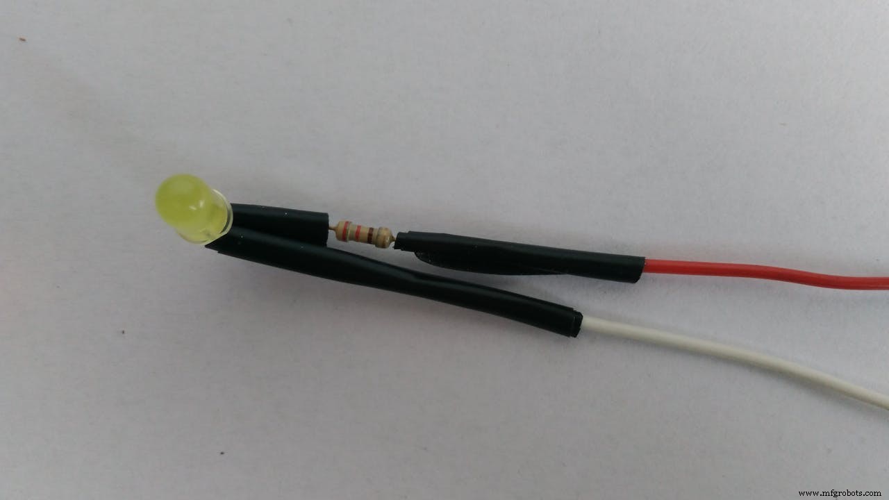
- solder the parts and cover them with electrical tape
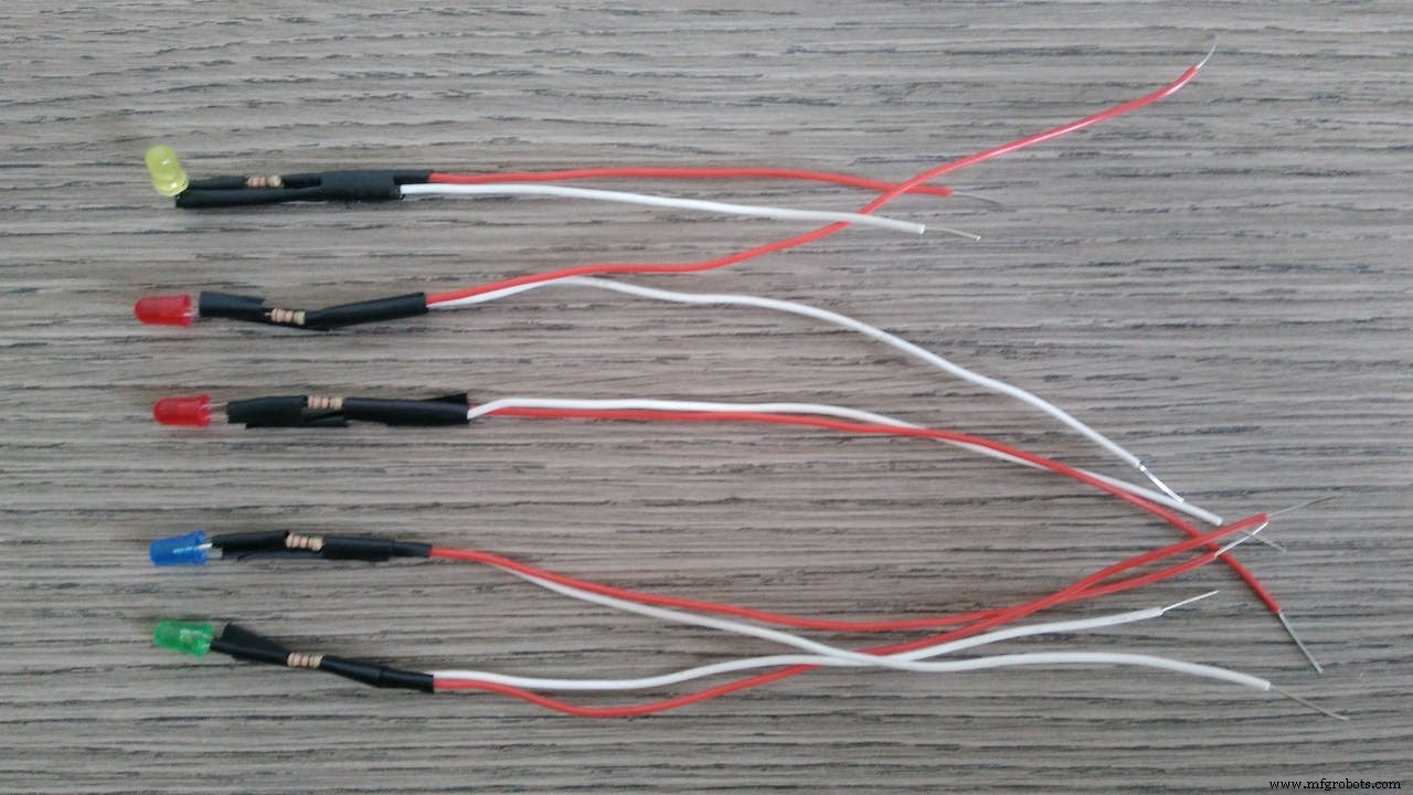
- connect all the white cables to a single white cable (this will go to the gnd) and solder them all together
Now connect the red wires to your Arduino: GREEN led to pin 9, YELLOW led to pin 11, RED led to pin 12, BLUE led to pin 13 and the last RED to pin A2.
Grove sensors:
Connect the grove sensors to the shield (see scheme on attachments).
Buzzer to D3, LCD RGB to I2C, Temperature sensor to A0, Sound sensor to A1.
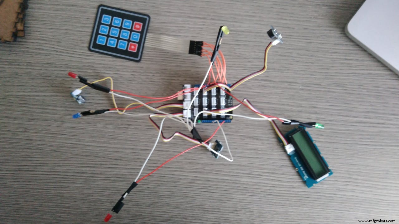
Ok, now we have connected all the electric parts. Now you need the case.
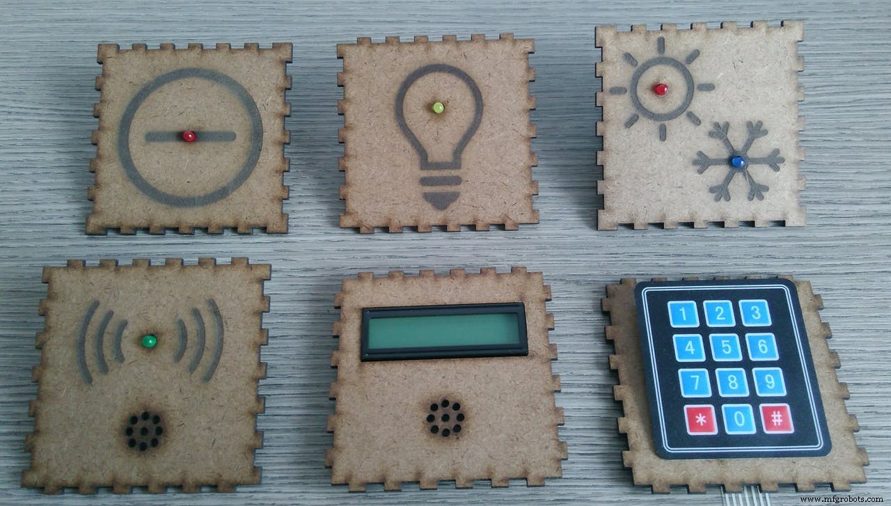
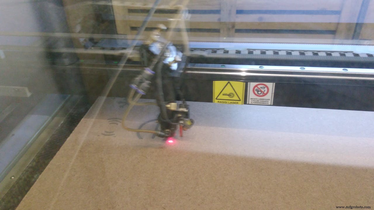
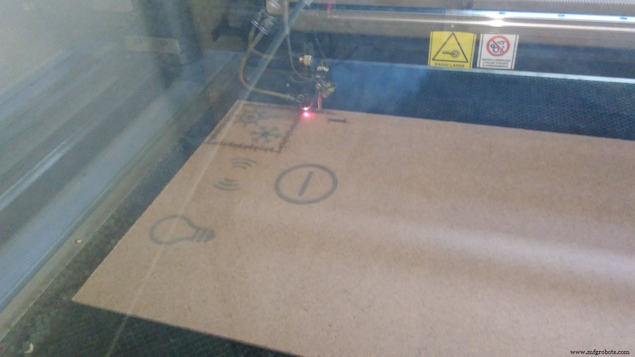
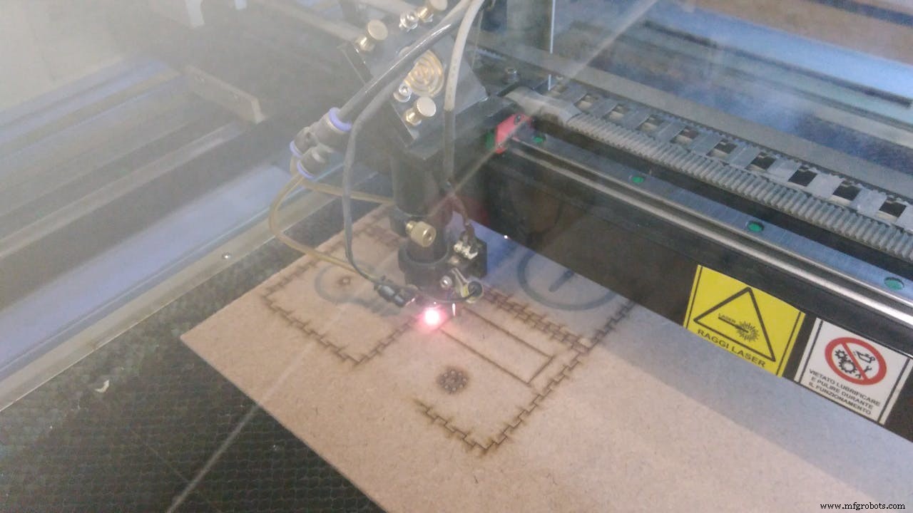
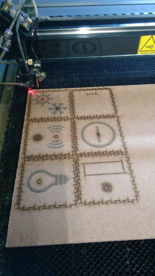
Hardware - boxYou can download the sketch of the cube to cut with laser. The red lines in the sketch are the symbols of the faces, just engrave them. The black lines should be cut. The internal dimension of the cube is 9 cm. The sketch is ok if you use a 3mm material, if you use a different thickness you should modify it (you can use this website: http://www.makercase.com/).
The material I choose is MDF (Medium Density Fiber) but you can use what you want.
Here are some pictures of the laser cut:
Now we have to assemble it.
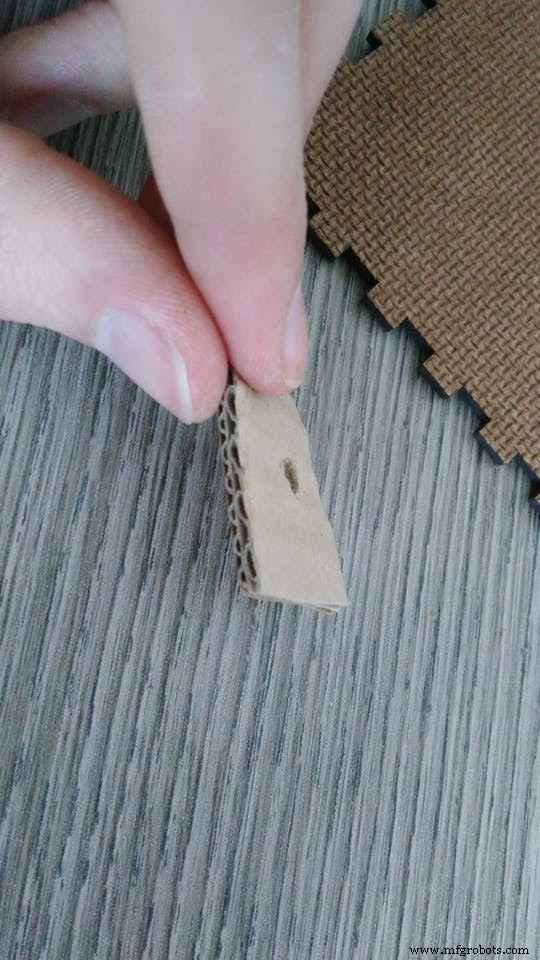
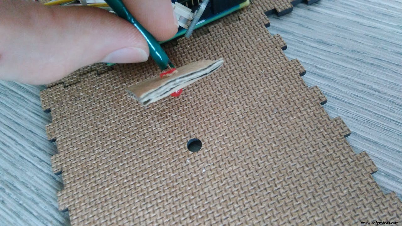
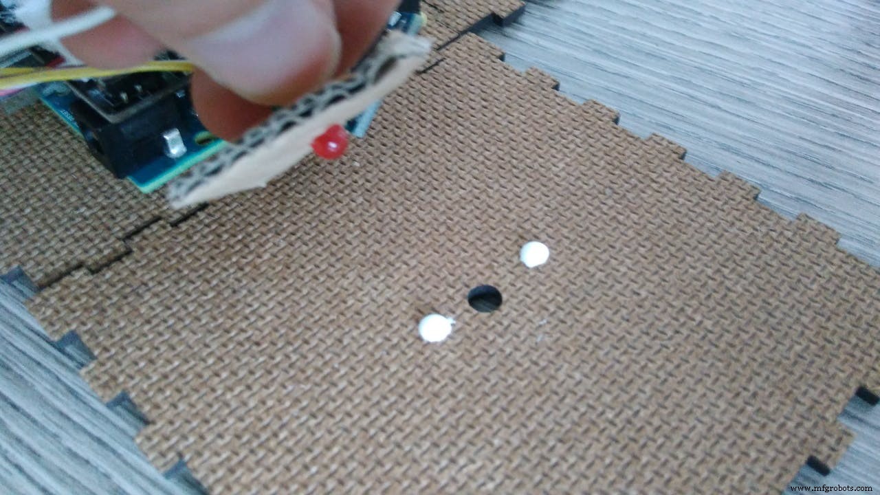
I glued some pieces of cardboard to make thickness for the led. In this way they will be aligned with the surface.
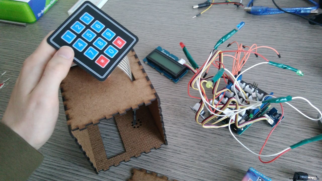
Now we mount the keypad. Insert it in the hole and remove the adhesive film, then reconnect the pins.
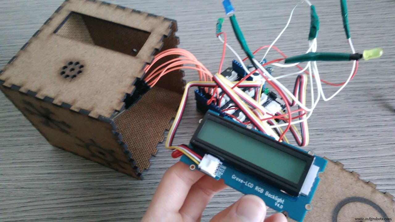
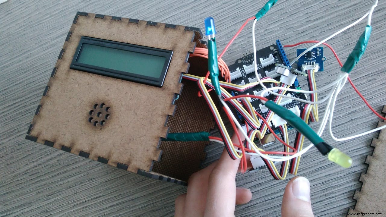
Now the RGB LCD. This fit perfectly the hole.
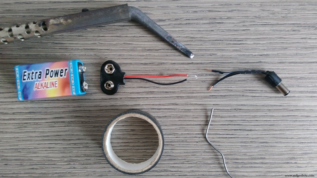
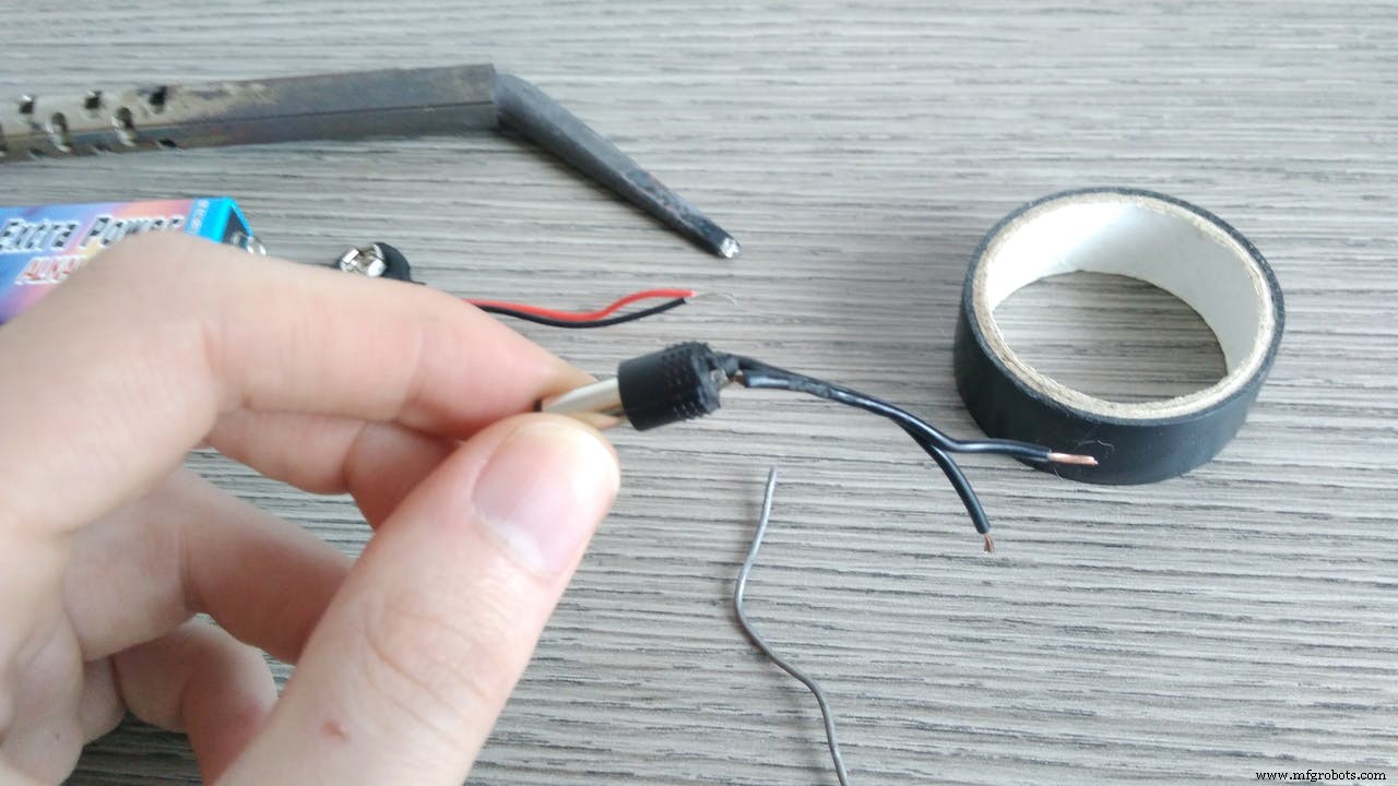
Let's prepare the battery connector:
I have cut an old transformer plug and connected it to a battery clip. In this way we save space inside the box.
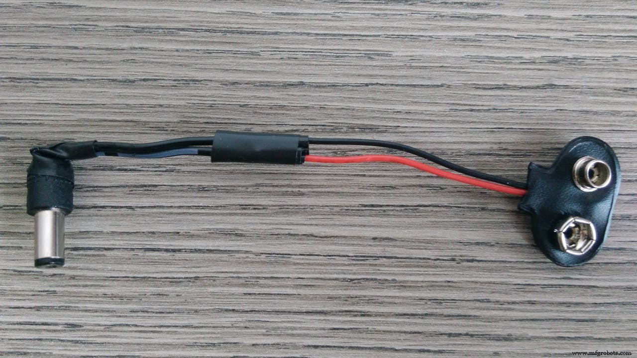
At this point thats what you should have:
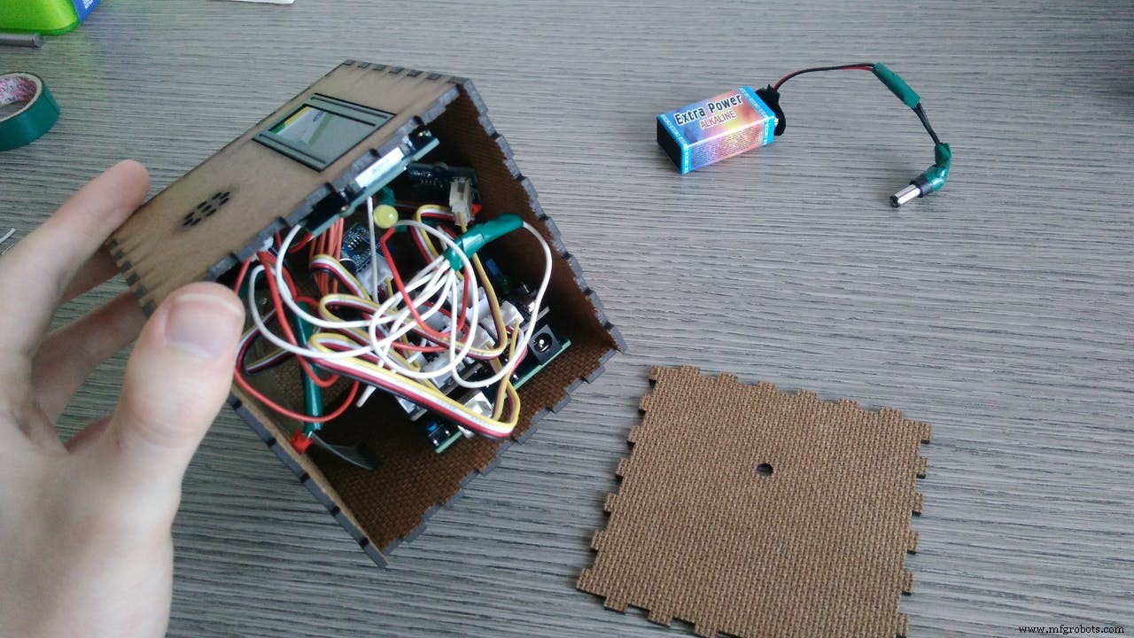
Now you just need to connect the battery, upload the code and close the cube!
TIP: fix the board and the battery with the case so that when you shake the cube they will be stable.
You can find the code in the attachments. Upload it in your board with the Arduino IDE (remember to update your software for Arduino 101 compatibility).
I have commented almost every line of the code to make it more understandable that I can. Don't be afraid of the 500+ lines, the structure it's not so complicate.
At the beginning there are the libraries and all the variables declaration.
In this part there is also the definition of BLE services and characteristic. I used Automation IO service. I used the Digital characteristic for lights and temperature (this use 2 bit , so 4 possible cases to codify) and the Analog for TV (to send all the codes of the keypad).
Then the setup. This pat is executed only one time at the beginning. Here we initialize the components as inputs or outputs and initialize the BLE and the gyro of the 101 board.
The main part is the loop. It is divided in four parts:
- 1 The first part is copied from Arduino website tutorial: (https://www.arduino.cc/en/Tutorial/Genuino101CurieIMUAccelerometerOrientation ) this part is constantly executed and it returns the orientation of the board.
- 2 The second part we activate a face only if it is in the up position for more than two seconds. We use the millis function to count the time. When the position change it memorize the millis value and if the orientation remain the same, after an interval (2 sec), we enter in an if-zone where the selected face became true (for the 4th part).
- 3 The third part is activated only if the cube is shaked with a certain intensity and for more than 2 seconds. The last activated face function is closed and the face is set as false. If the face is false can't enter in the 4th part.
- 4 The fourth part is only for true faces. Here there is the core of the functions of the smart cube. In this part are constantly executed only the faces that are true in loop.
You can modify the face functions with some modifications of the code. The main structure should be as described. You can change the part inside the if conditions of every face.
if (face2 == true) { // TEMPERATURE face
//START CHANGING HERE
 digitalWrite (LEDOFF, LOW); // if this face is true the OFF face led is LOW
 if (central.connected() == true) { // if the cube is BLE connected
  // read temperature value
  int val = analogRead(pinTemp); // get analog value
  resistance=(float)(1023-val)*10000/val; // get resistance
  temperature=1/(log(resistance/10000)/B+1/298.15)-273.15;
  // calculate temperature
  //conditions of activation
  if (temperature > tooHot) { // activate air conditioning
   digitalWrite(LEDhot, LOW); // close heating led
   digitalWrite(LEDcold, HIGH); // open air conditioner led
   termoChar.setValue(1); // set via BLE the condition 1 = cold on - hot off
  }
  if (temperature < tooCold) { // activate heating
   digitalWrite(LEDhot, HIGH);
   digitalWrite(LEDcold, LOW);
   termoChar.setValue(2); // 2 = cold off - hot on
  }
  if (temperature > tooCold && temperature < tooHot) {
   // ideal temperature: nothing is activated
   digitalWrite(LEDhot, LOW);
   digitalWrite(LEDcold, LOW);
   termoChar.setValue(0); // 0 = cold off - hot off
  }
 }
//END HERE
}
You have to code the "true" part (as in the previous code) and also the "false" part when the cube is shaked:
// TEMPERATURE deactivation
if (lastFUNCTION == 2) { // TEMPERATURE face
 //START CHANGING HERE
 // if a central is connected to peripheral:
 if (central.connected() == true) {
  digitalWrite(LEDhot, LOW); // close temperature red led
  digitalWrite(LEDcold, LOW); // close temperature blue led
  termoChar.setValue(0); // temperature BLE signal: 0 = cold off - hot off
 //END HERE
 }
Serial.println("TEMPERATURE false - CLOSE");
face2 = false; // TEMPERATURE face became false
}
Remember to set the face as false when you shake it.
App:To see the cube BLE outputs you can download this app: nRF Connect
https://play.google.com/store/apps/details?id=no.nordicsemi.android.mcp&hl=it
When you open it, just search for devices and connect with "smartcubesketch". Then you will see three "Automation IO" tabs, click on them and push the continuous data collector.
It is important to connect the cube because some functions (lights, temperature and tv) are executed only if the cube is connected.
How it works: VIDEOUpload the code, insert the battery, close the box and...
...now you have a SMART CUBE!
I made a video to show you all the functions of the cube and how to use it.
ConclusionsThis project is only the first step to a smart home. My purpose was to use the Arduino 101 board potentiality to create something new. I think that the accelerometer and gyroscope give to the board new opportunities in terms of mobility. With the BLE, in addition of being portable, is also easy to connect.
This is the fist time that I realize concretely one of my projects (I mean with a working prototype). It was hard and there were some difficulties during the road but at the end I've learn a lot and I'm happy with the result. I hope that also everyone who read this guide could learn something from my work and also modify this project on their needs. I'm sorry for my bad english but I hope that the images could help you.
In the future of this project I expect to create the centraline that is like the bridge between the smart cube and the actuators (lights, temperature, tv...). This centraline will receive the BLE signal from the cube and use this information to do smart things in your home.
I'm very happy to have the opportunity to use Arduino 101 and the Grove kit (the kit is very simple and fast for prototyping).
I hope that using the board in this way could be an inspiration for your project. You can personalize it as you want: I'm curious to see what functions will you create and in what different context you will use it!
Maybe this is not a revolution but it's a new way to interact with your home.
Hope you like this tutorial.
Now it's your turn: put your hands on the cube and hack it!
Code
- SMART CUBE - complete code with comments
SMART CUBE - complete code with commentsArduino
This is the code to upload on your Arduino 101. You can use this code as it is or customize based on your needs. Follow the comments to understand how it works.// Libraries
#include "CurieIMU.h" // Acelerometer & Gyroscope
#include <CurieBLE.h> // Bluetooth Low Energy
#include <Wire.h>
#include "rgb_lcd.h" // LCD
#include <Keypad.h> // Keypad
rgb_lcd lcd; // LCD initialization
// Bluetooth initialization:
BLEPeripheral blePeripheral; // BLE Peripheral Device (the board you're programming)
// BLE Services
BLEService lightsService("1815"); // BLE Automation IO (1815) - lights informations
BLEService termoService("1815"); // BLE Automation IO - temperature informations
BLEService TVService("1815"); // BLE Automation IO - tv informations
// BLE characteristic
BLEUnsignedCharCharacteristic lightsChar("2A56", // BLE characteristic Digital (2A56) - lights
BLERead | BLENotify);
BLEUnsignedCharCharacteristic termoChar("2A56", // BLE characteristic Digital - temperature
BLERead | BLENotify);
BLEUnsignedCharCharacteristic TVChar("2A58", // BLE characteristic Analog (2A58) - tv
BLERead | BLENotify);
// Constant and variables declaration:
// Face orientation and shake functions:
int lastOrientation = - 1; // previous orientation (for comparison)
unsigned long previousMillis = 0; // last time update
unsigned long interval = 2000; // time to wait in up position before the face activation
unsigned long SHAKEpreviousMillis = 0; // last time update
unsigned long SHAKEinterval = 2000; // time to wait during shaking for face deactivation
boolean keep = false; // this is used to count only one time the face orientation change
int lastFUNCTION = -1; // this is used to know what is the previous rientation
// Faces initilization: at the beginning every face is false
boolean face0 = false;
boolean face1 = false;
boolean face2 = false;
boolean face3 = false;
boolean face4 = false;
boolean face5 = false;
// LIGHTS face
const int LEDlights = 11; // pin 11: yellow led
// TEMPERATURE face
const int pinTemp = A0; // pin A0: temperature sensor
const int LEDhot = 12; // pin 12: red led
const int LEDcold = 13; // pin 13: blue led
float temperature; // temperature value memorization
int B=3975; // B value of the thermistor
float resistance; // resistance value memorization
float tooHot = 26.0; // temperature at which the air conditioner is activated [SET]
float tooCold = 23.0; // temperature at which the heater is activated [SET]
// TIMER face
int BUZZER = 3; // pin 3: buzzer
boolean KEEPtime = false; // this is used to count only one time the face orientation change (not restart while counting)
int TIMERmillis = 0; // the following are for the countdown determination
int prevSHOWsecond = 0;
int CountdownInMillis = 0;
int SHOWmillis = 0; // millis value calculation result
int SHOWminute = 0; // minutes value to show in the monitor for the countdown
int SHOWseconds = 0; // seconds value to show in the monitor for the countdown
const int SETminute = 2; // set 2 minute timer [SET]
const int SETsecond = 30; // set 30 seconds timer [SET]
// SOUND face
const int soundLED = 9 ; // pin 9: green led
const int soundSENSOR = A1; // pin A0: sound sensor
int brightness = 0; // green led brightness initialization
// TV face
const byte ROWS = 4; // four rows keypad
const byte COLS = 3; // three columns keypad
char keys[ROWS][COLS] = {
{'1','2','3'},
{'4','5','6'},
{'7','8','9'},
{'*','0','#'}
}; // keypad button values
byte rowPins[ROWS] = {10,8,7,6}; // pin 10,8,7,6: connect to the row pinouts of the keypad
byte colPins[COLS] = {5,4,2}; // pin 5,4,2: connect to the column pinouts of the keypad
Keypad keypad = Keypad( makeKeymap(keys), rowPins, colPins, ROWS, COLS ); // keypad initialization
// OFF face
const int LEDOFF = A2; // pin A2: red led
void setup() {
pinMode(LEDlights, OUTPUT); // every led is set as an output
pinMode(LEDhot, OUTPUT);
pinMode(LEDcold, OUTPUT);
pinMode(soundLED,OUTPUT);
pinMode(LEDOFF, OUTPUT);
Serial.begin(9600); // initialize Serial communication
CountdownInMillis = (SETminute*60 + SETsecond)*1000; // this calculates the corrispondent value in millis from the minutes and seconds setting
lcd.begin(16, 2); // LCD initialization
lcd.setRGB(0, 0, 0); // LCD RGB is OFF at the beginning
// initialize device
Serial.println("Initializing IMU device...");
CurieIMU.begin();
// Set the accelerometer range to 2G
CurieIMU.setAccelerometerRange(2);
// Enable Shock Detection
CurieIMU.setDetectionThreshold(CURIE_IMU_SHOCK, 7000); // 7.0g = 7000 mg (this value set the intensity of the shock)
CurieIMU.setDetectionDuration(CURIE_IMU_SHOCK, 2000); // 2000ms (this value set the duration of the shock)
CurieIMU.interrupts(CURIE_IMU_SHOCK);
// BLE setup initialization
blePeripheral.setLocalName("SmartCubeSketch"); // the name of the project
blePeripheral.setAdvertisedServiceUuid(lightsService.uuid()); // add the lights service UUID
blePeripheral.addAttribute(lightsService); // add the BLE lights service
blePeripheral.addAttribute(lightsChar); // add the BLE lights characteristic
lightsChar.setValue(3); // initial value for this characteristic = 3
//BLE lights value meaning: 0 = lights off, 1 = lights on, 3 = initial state, 4 = not used
blePeripheral.setAdvertisedServiceUuid(termoService.uuid()); // add the temperature service UUID
blePeripheral.addAttribute(termoService); // add the BLE temperature service
blePeripheral.addAttribute(termoChar); // add the BLE temperature characteristic
termoChar.setValue(0); // initial value is 0: cold off - hot off
//BLE termo value meaning: 0 = cold off - hot off, 1 = cold on - hot off, 2 = cold off - hot on, 3 = not used
blePeripheral.setAdvertisedServiceUuid(TVService.uuid()); // add the tv service UUID
blePeripheral.addAttribute(TVService); // add the BLE tv service
blePeripheral.addAttribute(TVChar); // add the tv characteristic
TVChar.setValue('x'); // initial value for this characteristic (x means nothing)
//BLE TV value meaning: #number corrispond to the pressed button, C: close TV, O: open TV, x: initial state
blePeripheral.begin();
Serial.println("Bluetooth device active, waiting for connections...");
} // setup end
void loop() {
BLECentral central = blePeripheral.central(); // BLE connection
unsigned long currentMillis = millis(); // current value of time in milliseconds
// the following code comes from www.arduino.cc/en/Tutorial/Genuino101CurieIMUccelerometerOrientation
// it is used to detect the orientation of the board
int orientation = - 1; // the board's orientation
String orientationString; // string for printing description of orientation
// read accelerometer:
int x = CurieIMU.readAccelerometer(X_AXIS);
int y = CurieIMU.readAccelerometer(Y_AXIS);
int z = CurieIMU.readAccelerometer(Z_AXIS);
// calculate the absolute values, to determine the largest
int absX = abs(x);
int absY = abs(y);
int absZ = abs(z);
if ( (absZ > absX) && (absZ > absY)) {
// base orientation on Z
if (z > 0) {
orientationString = "up";
orientation = 0;
} else {
orientationString = "down";
orientation = 1;
}
} else if ( (absY > absX) && (absY > absZ)) {
// base orientation on Y
if (y > 0) {
orientationString = "digital pins up";
orientation = 2;
} else {
orientationString = "analog pins up";
orientation = 3;
}
} else {
// base orientation on X
if (x < 0) {
orientationString = "connector up";
orientation = 4;
} else {
orientationString = "connector down";
orientation = 5;
}
}
// end of the tutorial code.
// at this point you have the orientation value of the board constantly updated:
/*
The orientations of the board:
0: flat, processor facing up (TIMER)
1: flat, processor facing down (TV)
2: landscape, analog pins down (TEMPERATURE)
3: landscape, analog pins up (OFF)
4: portrait, USB connector up (LIGHTS)
5: portrait, USB connector down (SOUND)
*/
// for this project you need to know if the face has changed from the previous face function [lastFUNCTION != orientation]
// but this information is printed only if the face is in the UP position for more than [interval] time
// and only for one time [keep] (you don't nedd to constantly activate the face, you just need it one time)
// because the orientation value is constantly updated you need to start counting time when the orientation change [orientation != lastOrientation]
if (orientation != lastOrientation) { // if the orientation has changed, start to count time
lastOrientation = orientation; // memorize the current orientation of the face
previousMillis = currentMillis; // memorize the time when the face has changed
keep = false;
} else if (currentMillis - previousMillis > interval && keep == false && lastFUNCTION != orientation) {
//this condition print the orientation only if the face is up for an interval
//and only for one time (keep)
//and only if the face is different from the previous loop
Serial.println(orientationString); // print the orientation
// the current face [orientation] is set as true (that means that the face function is set as activated)
if (orientation == 1) { // TV face
face1 = true; // TV face becomes true
lastFUNCTION = orientation; // memorize this activation in [lastFUNCTION]
Serial.println("TV true"); // print the activated face
TVChar.setValue('O'); // O: open the tv signal (BLE): tv is open only one time
}
if (orientation == 4) { // LIGHTS face
face4 = true;
lastFUNCTION = orientation;
Serial.println("LIGHTS true");
}
if (orientation == 3) { // OFF face
face3 = true;
lastFUNCTION = orientation;
Serial.println("OFF true");
}
if (orientation == 5) { // SOUND face
face5 = true;
lastFUNCTION = orientation;
Serial.println("SOUND true");
}
if (orientation == 2) { // TEMPERATURE face
face2 = true;
lastFUNCTION = orientation;
Serial.println("TEMPERATURE true");
}
if (orientation == 0) { // TIMER face
face0 = true;
lastFUNCTION = orientation;
Serial.println("TIMER true");
if (KEEPtime == false) { // timer is activated only if it is the 1st cycle or has been stopped
TIMERmillis = currentMillis; // start counting time
}
}
keep = true; // [keep] change value so that, in the next loop, you can't enter in this condition if the face don't change (avoid to activate another time the same face)
}
// this condition is for the shake function: if you shake for more than [SHAKEinterval] time, the face is deactivated
if (CurieIMU.getInterruptStatus(CURIE_IMU_SHOCK) && currentMillis - SHAKEpreviousMillis > SHAKEinterval) {
Serial.println("SHAKE"); // print "SHAKE" if shake is detected
// the last activated face [lastFUNCTION] is set as false (that means that the face function is deactivated)
//TV deactivation
if (lastFUNCTION == 1) { // TV face
TVChar.setValue('C'); // C: close the tv BLE signal
Serial.println("TV false - CLOSE"); // print the closed face
face1 = false; // TV face becomes false
}
//LIGHTS deactivation
if (lastFUNCTION == 4) { // LIGHTS face
if (central.connected() == true) { // if a central is connected to peripheral:
lightsChar.setValue(0); // lights OFF BLE signal
digitalWrite (LEDlights, HIGH); // open the yellow led to see the cube in the dark
}
Serial.println("LIGHTS false - CLOSE");
face4 = false; // LIGHTS face become false
}
// OFF
if (lastFUNCTION == 3) { // OFF face
// OFF face shaked: everything is closed and red led OFF is open
digitalWrite (LEDOFF, HIGH); // red led OFF is on when cube is closed
// now close all the activated functions:
// CLOSE TV
TVChar.setValue('C'); // C: close the tv BLE signal
Serial.println("TV false - CLOSE");
face1 = false;
// CLOSE LIGHTS
Serial.println("LIGHTS false - CLOSE");
if (central.connected() == true) {
lightsChar.setValue(0);
digitalWrite (LEDlights, LOW); // lights led is closed if OFF face is shaked
}
face4 = false;
// CLOSE SOUND
analogWrite(soundLED, LOW); // close the sound led
Serial.println("SOUND false - CLOSE");
face5 = false;
//CLOSE TEMPERATURE
if (central.connected() == true) {
digitalWrite(LEDhot, LOW);
digitalWrite(LEDcold, LOW);
termoChar.setValue(0); // temperature BLE signal: 0 = cold off - hot off
}
Serial.println("TEMPERATURE false - CLOSE");
face2 = false;
// CLOSE TIMER
Serial.println("TIMER false - CLOSE");
lcd.setRGB(0, 0, 0); // the LCD RGB is closed
lcd.clear();
KEEPtime = false;
face0 = false;
// The cube is inactive, only OFF led is active
Serial.println("OFF false - CLOSE");
face3 = false; // OFF face becomes false
}
// SOUND deactivation
if (lastFUNCTION == 5) { // SOUND face
analogWrite(soundLED, LOW); // close the sound led
Serial.println("SOUND false - CLOSE");
face5 = false; // SOUND face becomes false
}
// TEMPERATURE deactivation
if (lastFUNCTION == 2) { // TEMPERATURE face
// if a central is connected to peripheral:
if (central.connected() == true) {
digitalWrite(LEDhot, LOW); // close temperature red led
digitalWrite(LEDcold, LOW); // close temperature blue led
termoChar.setValue(0); // temperature BLE signal: 0 = cold off - hot off
}
Serial.println("TEMPERATURE false - CLOSE");
face2 = false; // TEMPERATURE face became false
}
// TIMER deactivation
if (lastFUNCTION == 0) { // TIMER face
Serial.println("TIMER false - CLOSE");
face0 = false; // TIMER face became false
// if you shake the cube when the time is running, the LCD became red and show the remaining time to countdown
lcd.setRGB(180, 40, 0); // the RGB backlight become red
lcd.clear(); // lcd is cleared
lcd.setCursor(0, 0);
lcd.print("STOP AT ");
lcd.setCursor(8, 0);
lcd.print(SHOWminute); // indicates the minutes when you shake the cube
lcd.setCursor(9, 0);
lcd.print(":");
lcd.setCursor(10, 0);
lcd.print(SHOWseconds); // indicates the seconds when you shake the cube
tone(BUZZER,1000,1000); // it make a short sound
delay(2000);
lcd.clear(); // clear the LCD
lcd.setRGB(0, 0, 0); // LCD RGB backlight is closed
KEEPtime = false; // TIMER face became false
}
SHAKEpreviousMillis = currentMillis; // memorize the value for the [SHAKEinterval] calculation
}
// the following instructions are executed in loop only if the face is activated
if (face1 == true) { // TV face
digitalWrite (LEDOFF, LOW); // if this face is true the OFF face led is LOW
if (central.connected() == true) { // if the cube is BLE connected
char key = keypad.getKey(); // read the value from the keypad
if (key && orientation == 1){ // if something is pressed and only when the tv face is up (avoid involuntary keypad pression)
if (key == '0') { // if the pressed key is 0
TVChar.setValue(key); // send the [key] value via BLE
Serial.println(key); // print the pressed button (comment if you don't want to show this information)
}
if (key == '1'){
TVChar.setValue(key);
Serial.println(key);
}
if (key == '2'){
TVChar.setValue(key);
Serial.println(key);
}
if (key == '3'){
TVChar.setValue(key);
Serial.println(key);
}
if (key == '4'){
TVChar.setValue(key);
Serial.println(key);
}
if (key == '5'){
TVChar.setValue(key);
Serial.println(key);
}
if (key == '6'){
TVChar.setValue(key);
Serial.println(key);
}
if (key == '7'){
TVChar.setValue(key);
Serial.println(key);
}
if (key == '8'){
TVChar.setValue(key);
Serial.println(key);
}
if (key == '9'){
TVChar.setValue(key);
Serial.println(key);
}
if (key == '*'){
TVChar.setValue(key);
Serial.println(key);
}
if (key == '#'){
TVChar.setValue(key);
Serial.println(key);
}
}
}
}
if (face4 == true) { // LIGHTS face
digitalWrite (LEDOFF, LOW); // if this face is true the OFF face led is LOW
if (central.connected() == true) { // if a central is connected to peripheral:
lightsChar.setValue(1); // LIGHTS activated BLE signal
digitalWrite (LEDlights, LOW); // yellow led is closed because the home lights are on
}
}
if (face3 == true) { // OFF face
// when OFF face is up nothing is done
digitalWrite (LEDOFF, LOW); // led OFF is activated only when the cube is shaked, so now is LOW
}
if (face5 == true) { // SOUND face
digitalWrite (LEDOFF, LOW); // if this face is true the OFF face led is LOW
// sound sensor is activated, led brightness regulated by the sond
// this code comes from brightness regulation example
long sum = 0;
for (int i=0; i<32; i++) {
sum += analogRead(soundSENSOR);
}
sum >>= 5;
brightness = (sum*255)/1024; // calculate the brightness value
analogWrite(soundLED,brightness); // green led brightness intensity is regulated by the noise
delay(50) ;
//end brightness example
}
if (face2 == true) { // TEMPERATURE face
digitalWrite (LEDOFF, LOW); // if this face is true the OFF face led is LOW
if (central.connected() == true) { // if the cube is BLE connected
// read temperature value
int val = analogRead(pinTemp); // get analog value
resistance=(float)(1023-val)*10000/val; // get resistance
temperature=1/(log(resistance/10000)/B+1/298.15)-273.15; // calculate temperature
//conditions of activation
if (temperature > tooHot) { // activate air conditioning
digitalWrite(LEDhot, LOW); // close heating led
digitalWrite(LEDcold, HIGH); // open air conditioner led
termoChar.setValue(1); // set via BLE the condition 1 = cold on - hot off
}
if (temperature < tooCold){ // activate heating
digitalWrite(LEDhot, HIGH);
digitalWrite(LEDcold, LOW);
termoChar.setValue(2); // 2 = cold off - hot on
}
if (temperature > tooCold && temperature < tooHot){ // ideal temperature: nothing is activated
digitalWrite(LEDhot, LOW);
digitalWrite(LEDcold, LOW);
termoChar.setValue(0); // 0 = cold off - hot off
}
}
}
if (face0 == true ) { // TIMER face activated
digitalWrite (LEDOFF, LOW); // if this face is true the OFF face led is LOW
// this calculate the time to show in the display
SHOWmillis = (CountdownInMillis - (currentMillis - TIMERmillis))/1000;
SHOWminute = SHOWmillis/60; // minutes value to show in the LCD
SHOWseconds = SHOWmillis%60; // seconds value to show in the LCD
lcd.setRGB(50, 100, 70); // open LCD with RGB blue color
if (prevSHOWsecond != SHOWseconds){ // refresh the screen every second (because refresh at every loop is too fast)
lcd.clear();
lcd.setCursor(0, 0);
lcd.print("TIMER ");
lcd.setCursor(7, 0);
lcd.print(SETminute); // writes the minutes that you set
lcd.setCursor(8, 0);
lcd.print(":");
lcd.setCursor(9, 0);
lcd.print(SETsecond); // writes the seconds that you set
lcd.setCursor(0, 1);
lcd.print(SHOWminute); // write the current remaining minutes
lcd.setCursor(1, 1);
lcd.print(":");
lcd.setCursor(2, 1);
lcd.print(SHOWseconds); // write the current remaining seconds
KEEPtime = true;
prevSHOWsecond = SHOWseconds; // to refresh every second
}
if (SHOWminute == 0 && SHOWseconds == 0) { // when countdown ends
lcd.clear(); // clear the LCD
lcd.setCursor(4, 0);
lcd.setRGB(180, 40, 0); // LCD RGB become red
lcd.print("TIME OUT");
tone(BUZZER,1000,500); // three sounds
delay (900);
tone(BUZZER,1000,500);
delay (900);
tone(BUZZER,1000,1000);
delay(1500);
lcd.clear(); // clear and close the LCD
lcd.setRGB(0, 0, 0);
face0 = false; // TIMER face is now closed (false)
KEEPtime = false;
}
}
} // loop end
Custom parts and enclosures
This is the file (.dxf) that you can upload on your laser cutter. I used a medium density fiberboard (MDF) of 3mm. Cut the black lines and engrave red lines. Important: if your material thickness is different you have to modify this sketch.smart_cube_8sVCflFmhM.dxfThe same file of the box but in a different format: .pdfSchematics
This is a .jpeg of the Fritzing scheme (yellow wires are connected to Grove components) This is a scheme of the connections in the Grove Shield_cI0IwUsPVZ.Base%20shield%20connections
Manufacturing process
- Solar Panels: A Wise Investment for Your Home
- Why a Slightly Bigger Design Can Accelerate Innovation and Reduce Risk
- Smart Home Evolution: What the Future Holds for Connected Living
- Smart Security: Expert Strategies to Shield Your Home IoT Devices from Hackers
- How to Strengthen Your Smart Home’s Security: Expert Tips
- Smart Plant IoT: Build a Connected Greenhouse with Arduino & Azure
- Seamless Smart Phone Control of Home Lighting Systems
- Control Your TV with Alexa: Arduino & ESP8266 Setup
- Smart Home System: Build a Low‑Cost Raspberry Pi & MediaTek Linkit Setup
- Home Energy Saver: Smart, Reliable, and Easy to Install