


Smart Automated Model Railway Layout with Passing Siding – Arduino‑Powered
Components and supplies
 |
| × | 1 | |||
 |
| × | 1 | |||
| × | 6 | ||||
 |
| × | 7 | |||
| × | 1 | ||||
| × | 1 | ||||
| × | 1 |
Apps and online services
 |
|
About this project
Making model train layouts is a great hobby, automating them will make it a lot better! Let us take a look at some of the advantages of its automation:
- Low-cost operation: The whole layout is controlled by an Arduino microcontroller, using an L298N motor driver, their cost is almost nothing as compared to traditional train control throttles and power packs.
- Ideal to put up at a display: Since no human interference is required to keep a control on the layout, you can use it at a display where you cannot be always present to control the train and the turnouts.
- Great for microcontroller hobbyists: If you are or want to start with Arduino and programming, this is a great project for you to practice your skills.
If you are interested, you can also check the previous version of this project which is even simpler.
So, without further ado, let's get started!
Step 1: Watch My Project WorkingStep 2: Get All the Parts and Components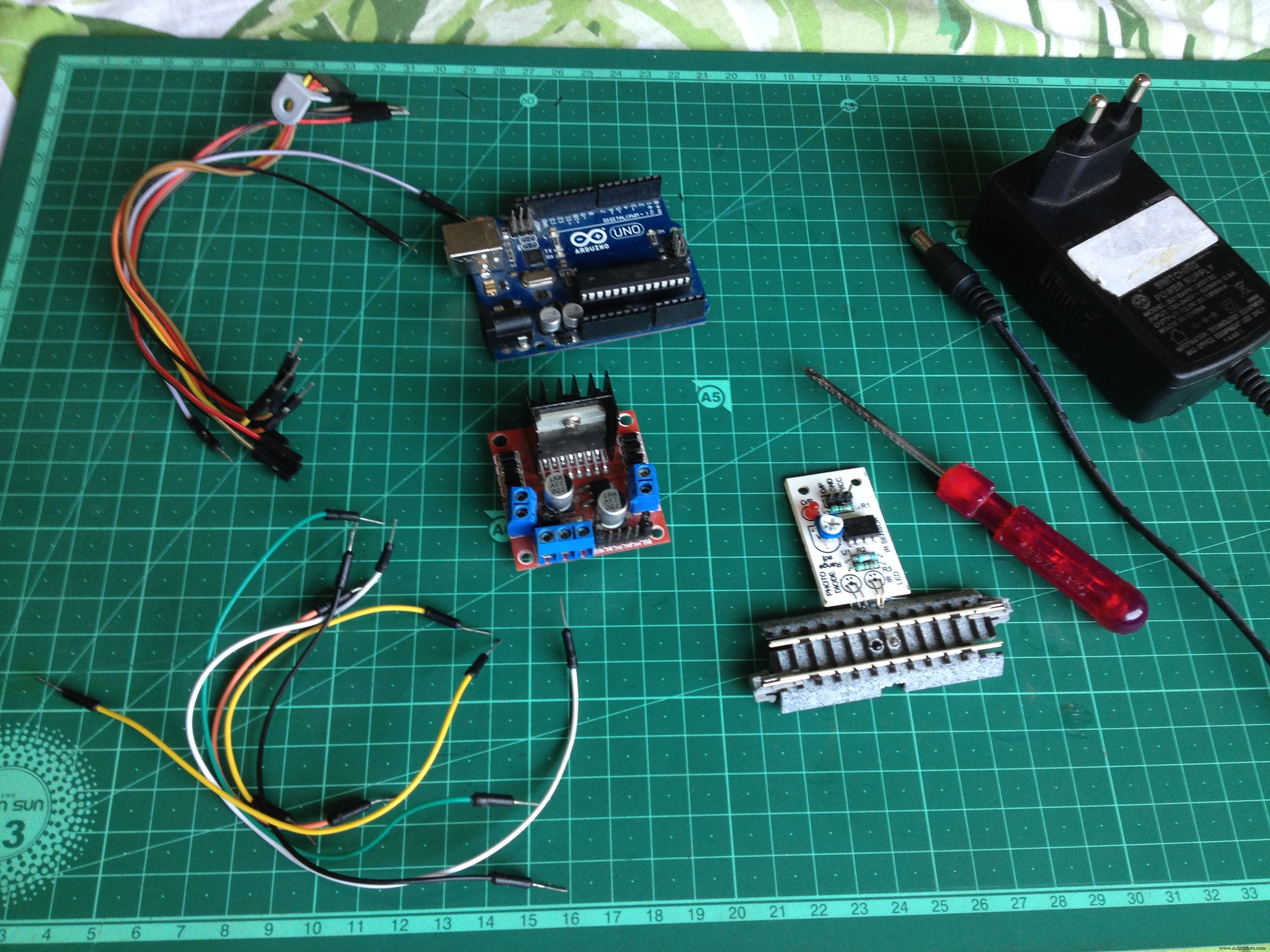
To start, make sure you have all of the following:
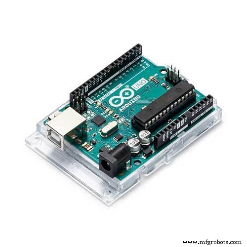
- An Arduino microcontroller board, UNO is preferred.
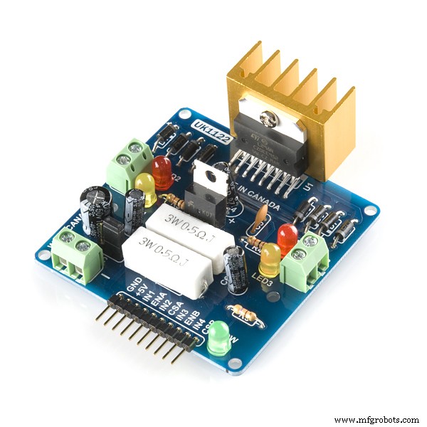
- An L298N dual H-bridge motor driver board.
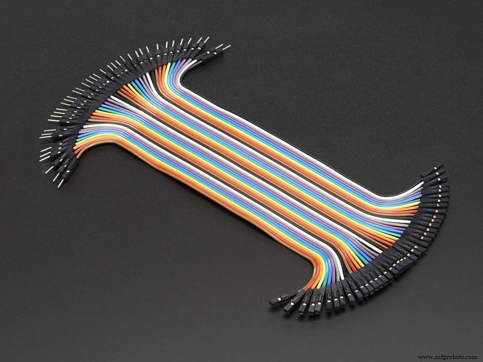
- 6 male to male jumper wires.
- 7 male to female jumper wires.
- A screwdriver.
- A 12 volt-DC power supply adapter.
- A track segment with IR proximity sensor attached on the underside(I used a Kato S62 track)
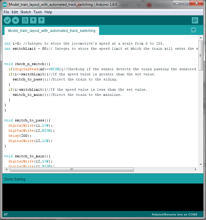
Download the Arduino IDE from here if you don't have it on your computer. Then download and open the given file.
Model_train_layout_with_automated_track_switching.inoStep 4: Lay the Tracks and Make the Layout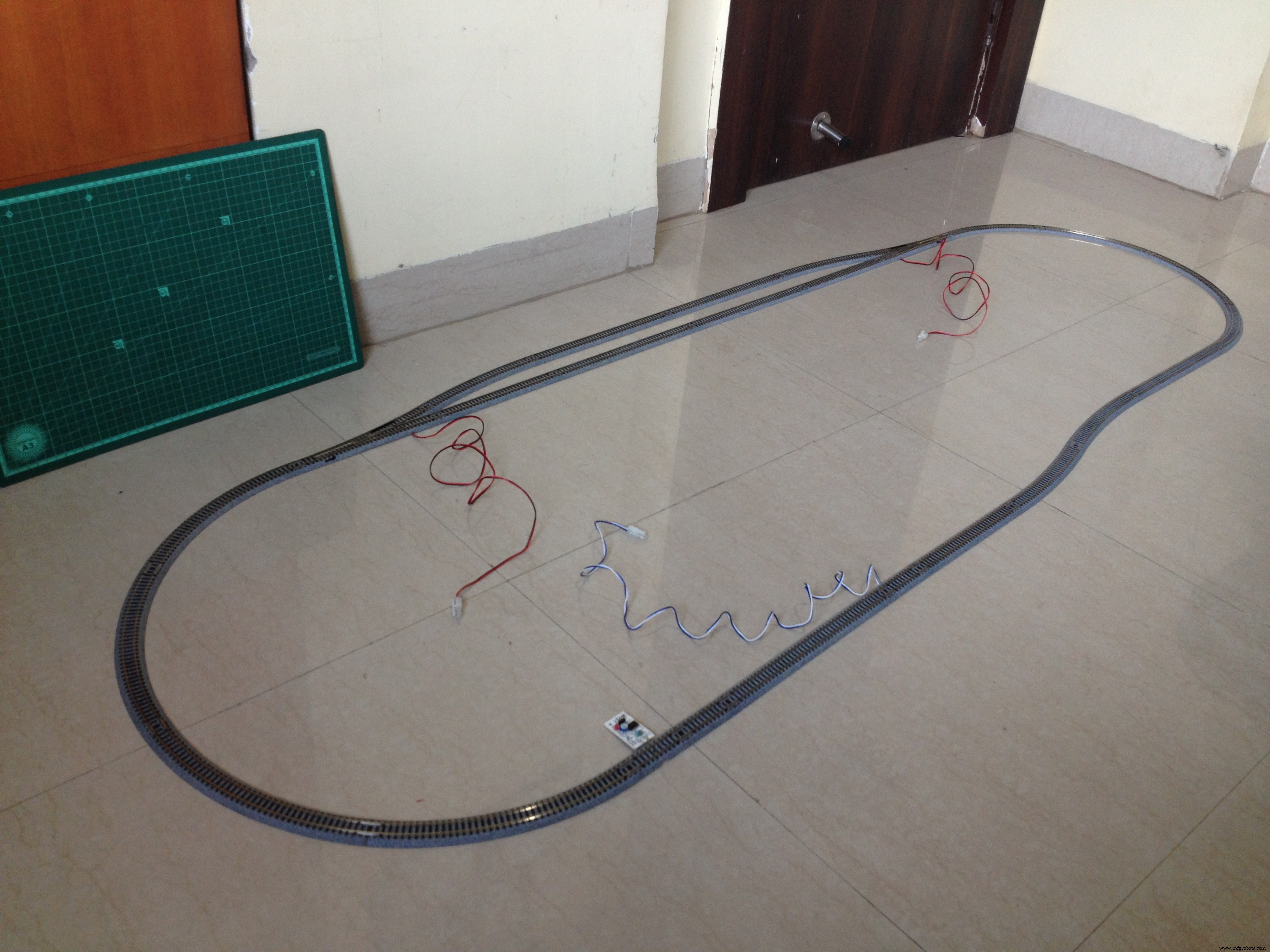
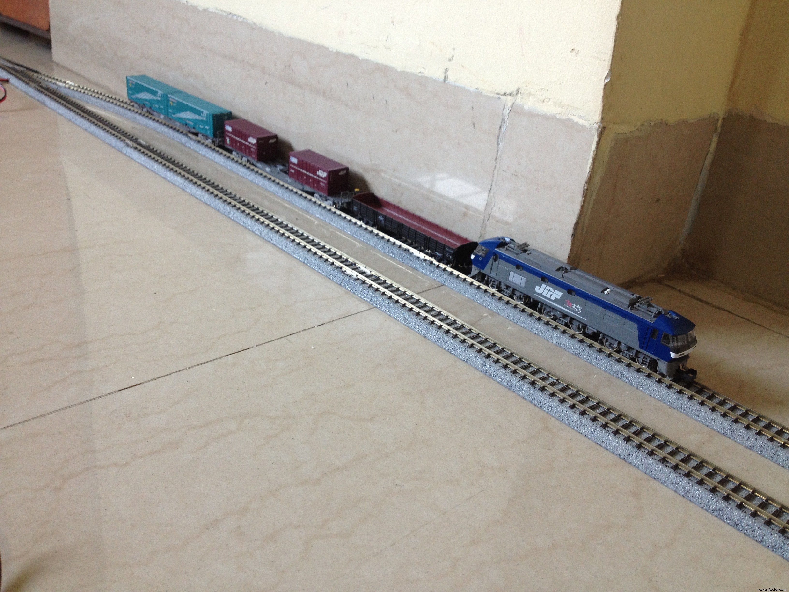
Make an oval loop with a passing siding somewhat as shown above. Make sure the distance between the sensor track and the first turnout the train will cross after crossing the sensor track is greater than the length of the train such that no part of the train is over the sensor track when it crosses the turnout.
Step 5: A Circuit Schematic Is Always Helpful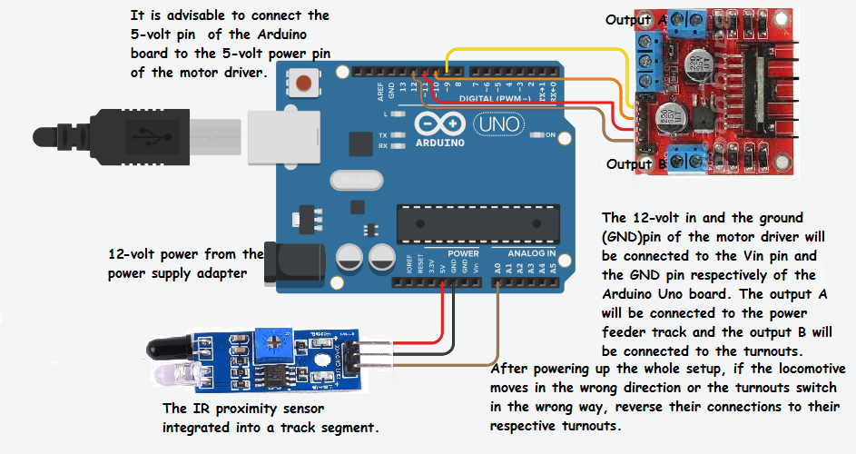
Make sure you go through the full circuit schematic and all of the details before proceeding.
Step 6: Connect the Turnouts to the Output of the L298N Driver Board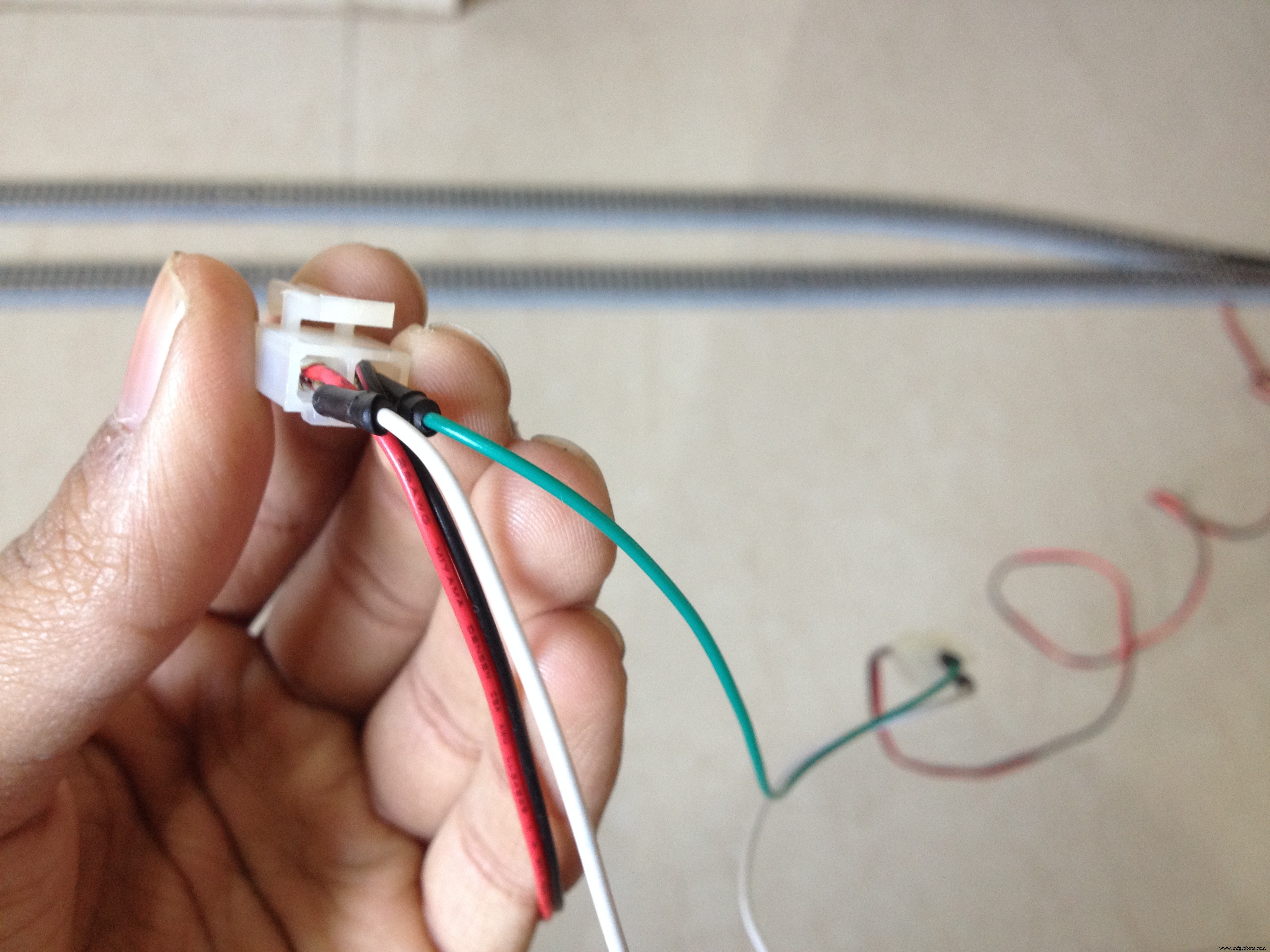
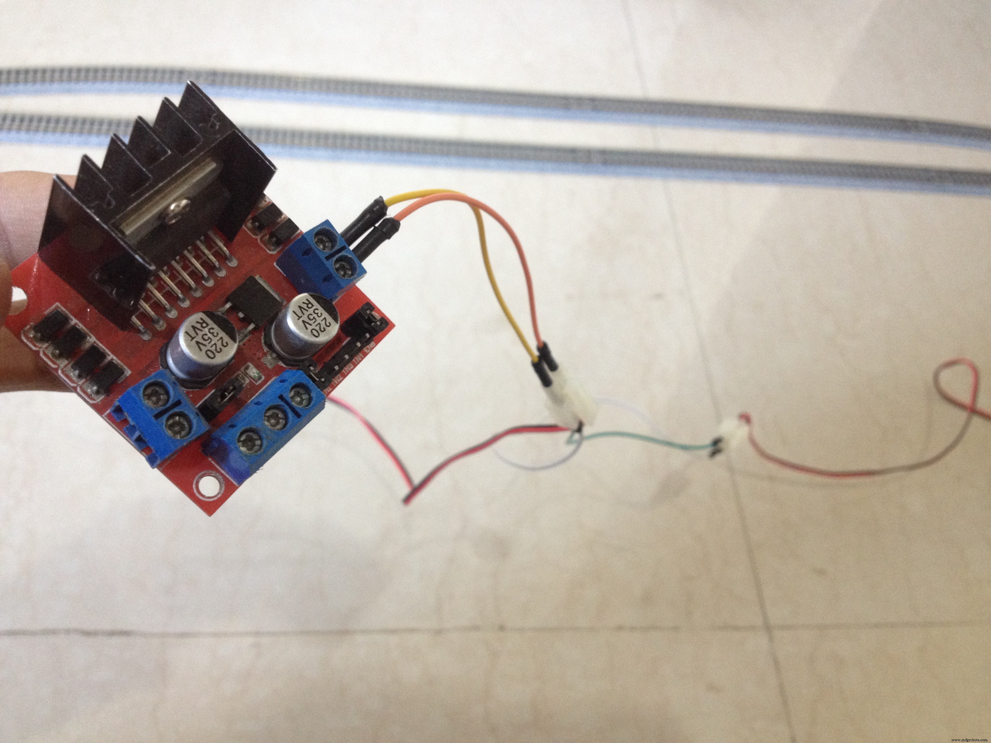
Connect the red and the black wires of both the turnouts respectively to each other, resulting in a parallel connection. Then, connect the red wires to the out4 and the black wires to the out3 terminal of the motor driver board.
Step 7: Connect the Power Feeder Track to the Remaining Output of the L298N Driver Board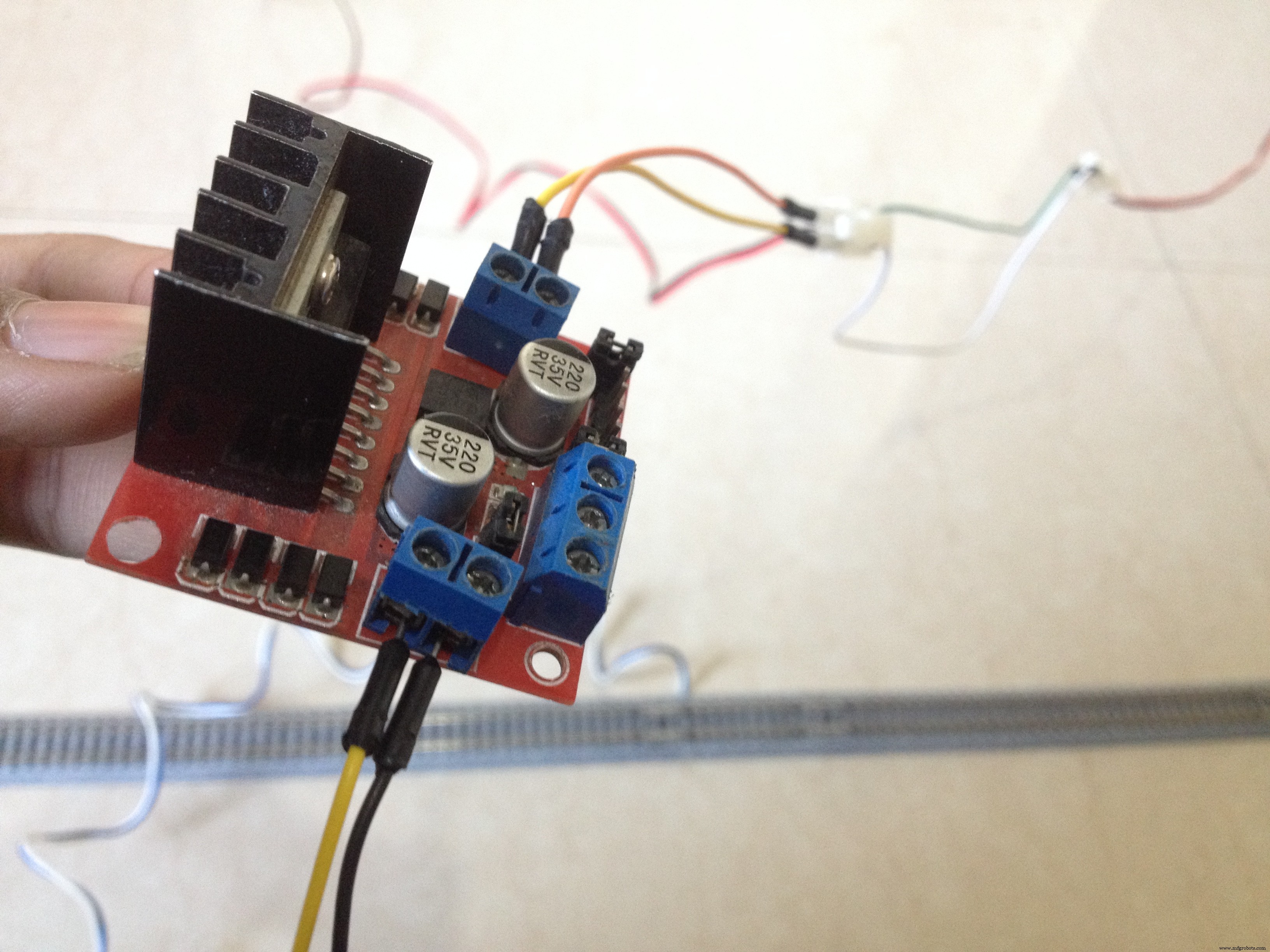
Connect the power feeder's white wire to the out1 and the blue wire to the out2 terminal of the motor driver board.
Step 8: Connect the L298N Driver Board to the Power Pins of the Arduino Board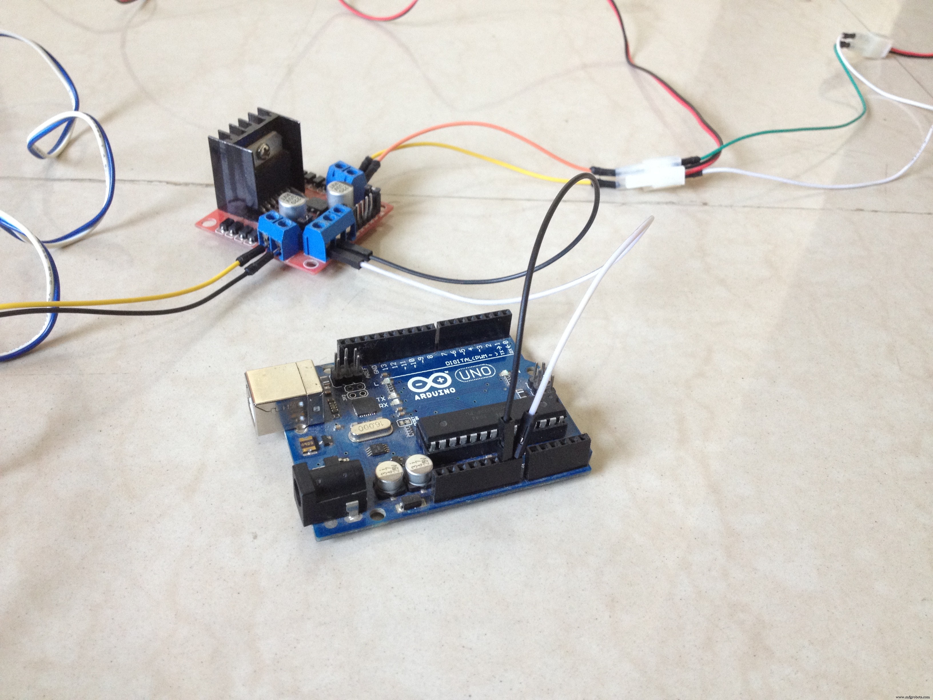
Connect the 12-volt pin to the VIN pin of the Arduino board, the GND pin to the GND pin of the Arduino board, and preferably, the 5-volt pin of the motor driver to the 5-volt pin of the Arduino board.
Step 9: Connect the Sensor to the Arduino Board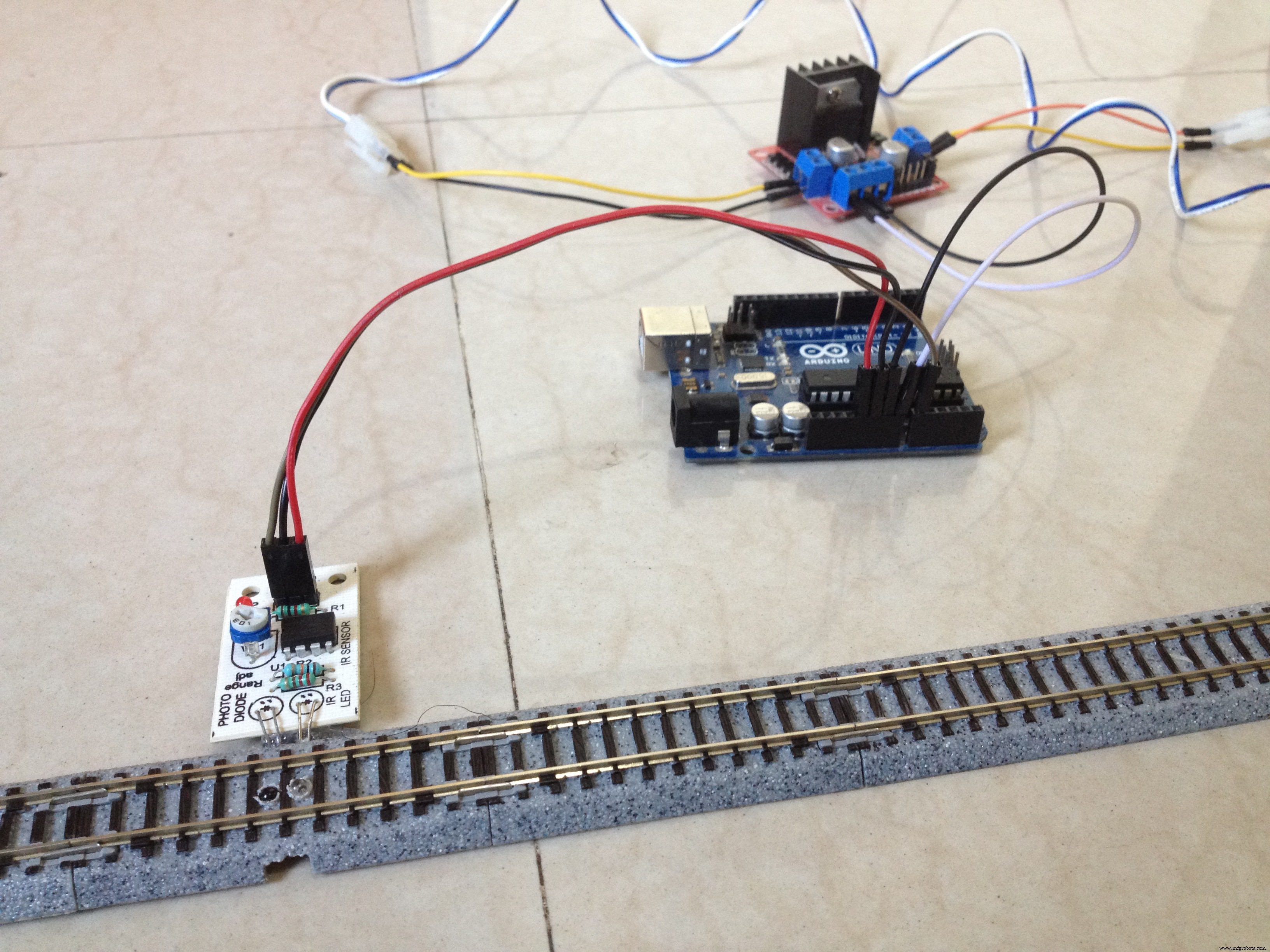
Connect the VCC pin of the sensor to the 5-volt pin of the Arduino board, GND pin to GND pin of the Arduino board, and the OUT pin to the A0 pin of the Arduino board.
Step 10: Connect the Input Pins of the Motor Driver to the Arduino Board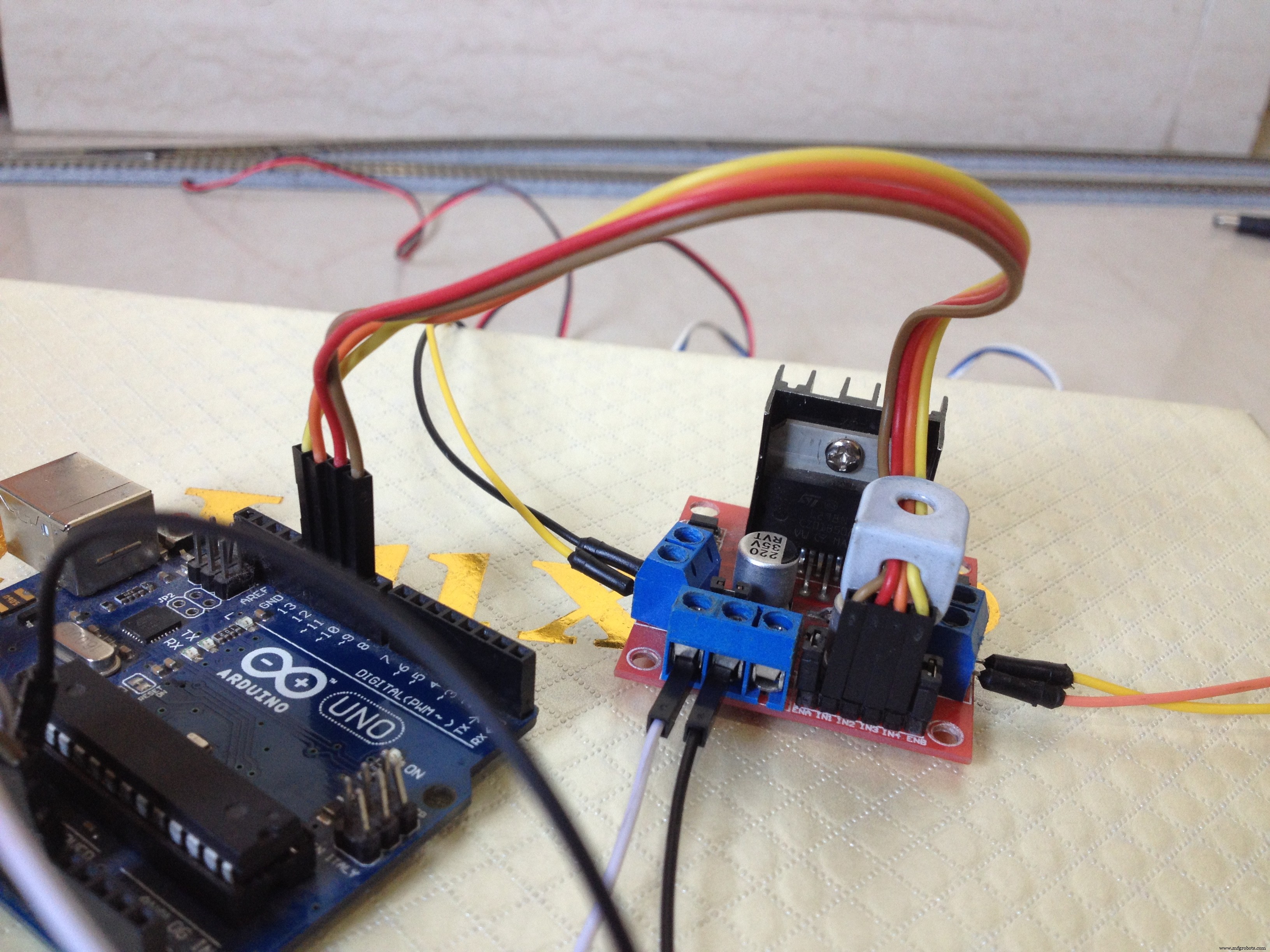
Connect the digital pins of the Arduino board to the input pins of the motor driver board as follows:
- D9 to IN1
- D10 to IN2
- D11 to IN3
- D12 to IN4
After checking all of the wiring connections, place the train on the siding.
Step 12: Power Up the Setup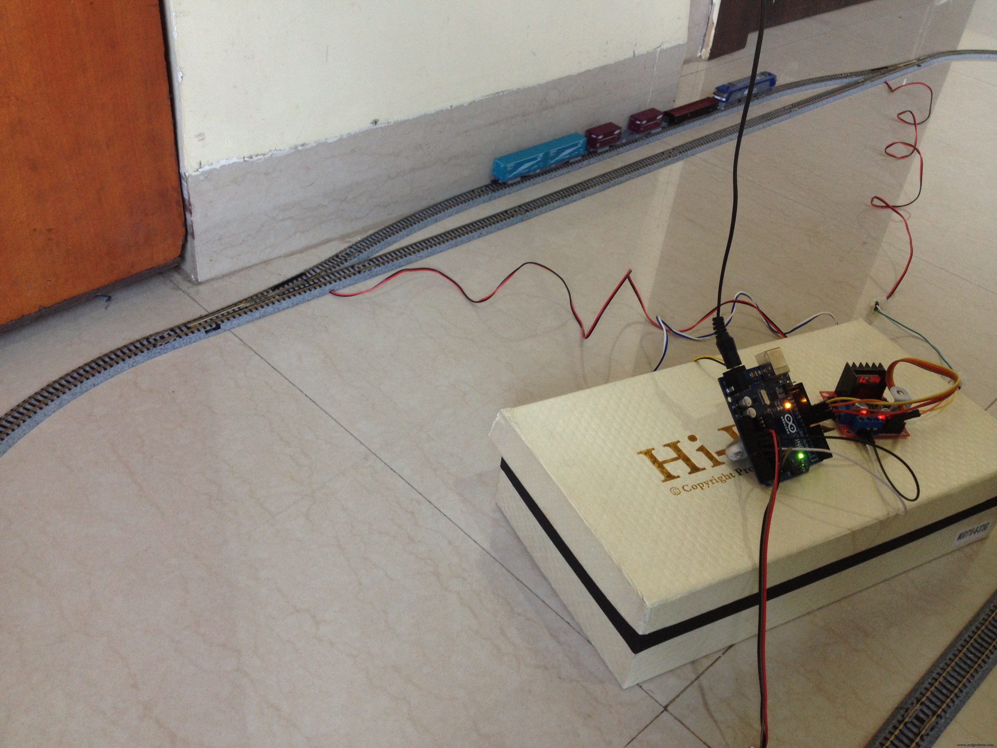
Power up the setup and make sure the turnouts get switched to the siding, if not then just reverse the connections of the turnouts made with the motor driver. Also, make sure the train starts to move to forward direction. Reverse the feeder track's connection with the motor driver if the train moves in the wrong direction.
Step 13: It's DONE!The project is complete, for now. You can tinker with the Arduino code to change the functionality of the layout, add more sidings, etc. It's all customizable! I would love to know about any modifications you make to this project. Let me know in the comments below. All the best!
Code
- Model_train_layout_with_automated_track_switching.ino
Model_train_layout_with_automated_track_switching.inoArduino
No preview (download only).
Schematics
Make sure you go through the schematic carefully.
Manufacturing process
- Automated Plant Watering System with Raspberry Pi & Web Dashboard
- Smart Hotel & Home Monitoring System with Cloud‑Based Automated Controls
- Recycling Sorting Robot Powered by Google Coral Edge TPU
- Elevate Automated Welding: Proven Strategies for Peak Performance & Reliability
- Smart Bus Stop Architectural Model Featuring Automatic Sunshade
- Interactive Countdown Timer with LED Display & Bluetooth Control
- Affordable Portable Cocktail Maker with Smart App Control
- Build a High-Performance Warehouse: Expert Layout Design & Launch Checklist
- DIY Automated Railway Crossing Gate: Safe, Reliable Train Detection System
- Robotic CNC Routing for Plastics: Boost Efficiency & Cut Costs