


Build Your Own Smart Pet Feeder with Arduino Nano
Components and supplies
 |
| × | 1 | |||
| × | 1 | ||||
| × | 1 | ||||
| × | 1 | ||||
| × | 1 | ||||
| × | 6 | ||||
 |
| × | 1 | |||
| × | 1 | ||||
| × | 1 | ||||
| × | 1 | ||||
 |
| × | 6 | |||
| × | 1 |
Apps and online services
|
About this project
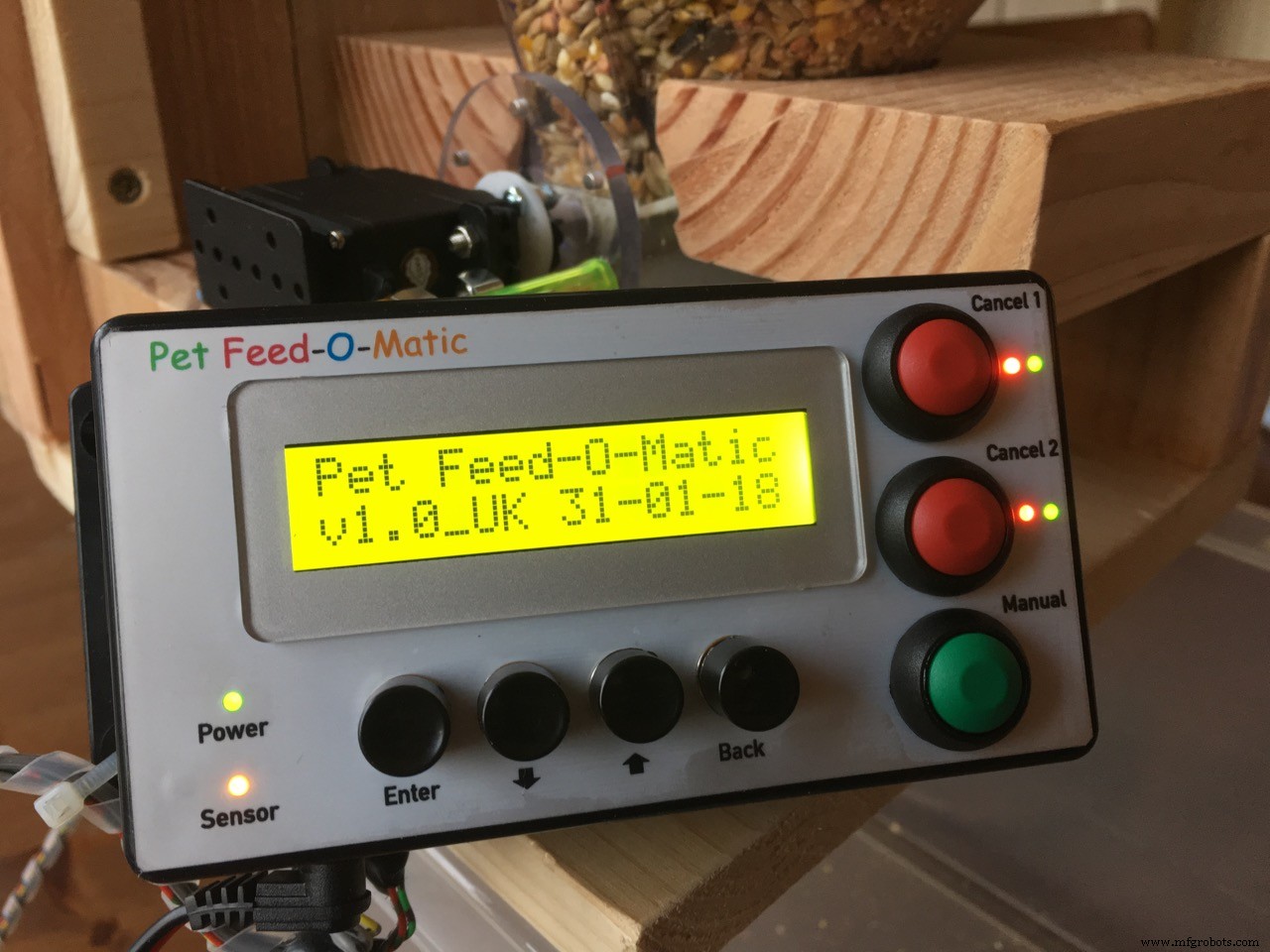
Update 2018-09-06My two pet feeders are working flawlessly for the past 7 months. We care for our pets during the day of course but they now get at regular times their feed. Very happy with the system!
Why another Pet Feeder?My version of a pet feeder is based on an Arduino microcontroller. The materials used are relatively cheap and I think it's easy to build!
Of course there are many version around but I could not find a complete project, ready to build with the features I needed so I started from scratch.
These are the features:
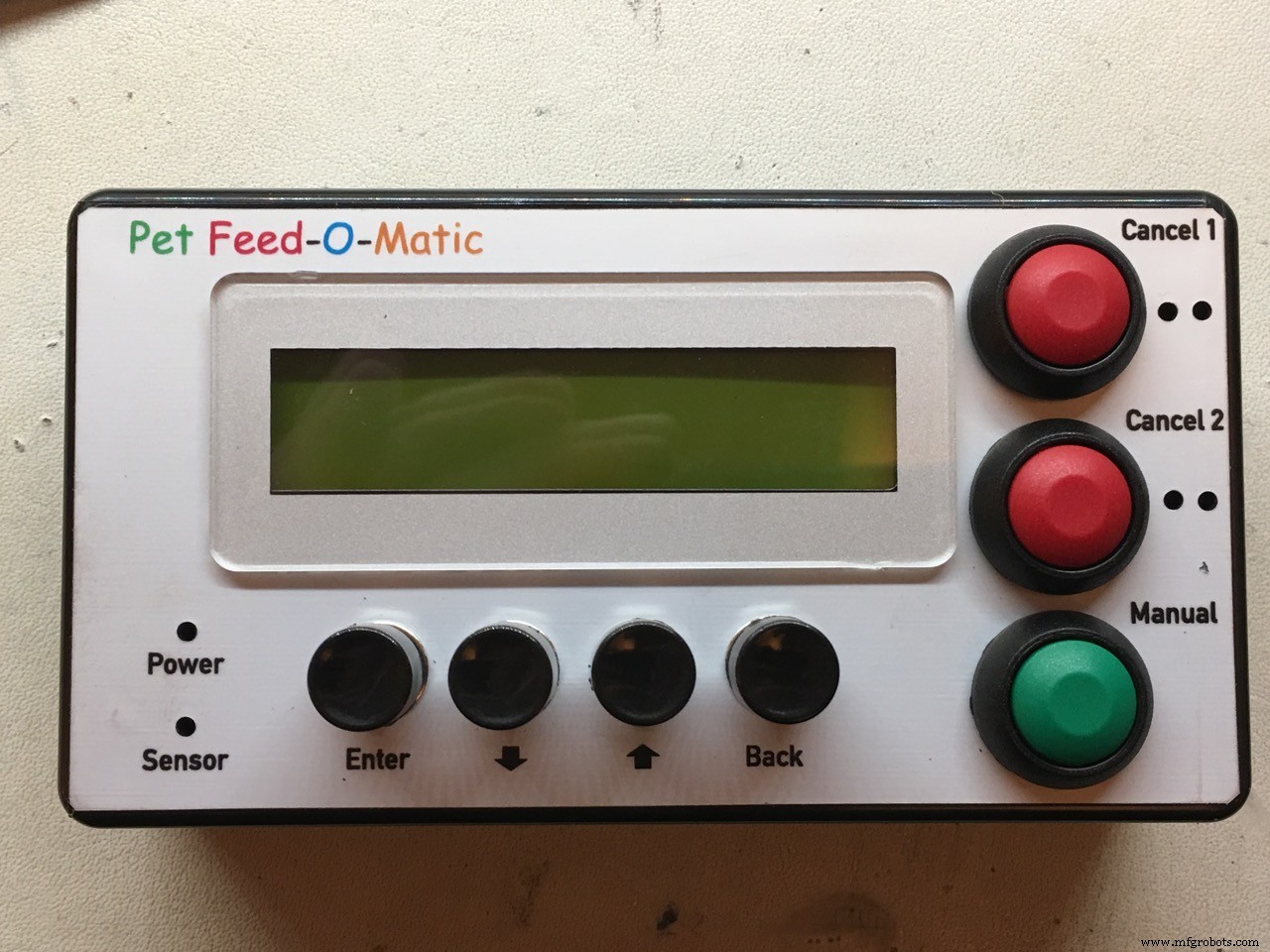
- *Accurate portions* delivered each time! (by using a Hall sensor)
- Two feeding times a day
- *Extremely* accurate Real Time Clock (Only with genuine DS3231 chip)
- You can cancel an upcoming feeding individually for both timers with display and Led indicator. Cancelling is automatically reset after the set time has passed.
- Manual feed function (one portion per button press)
- Adjustable portions for each of the two feeding times (1-9 portions)
- Overview of all set parameters in the main screen
- Easy to navigate menu system
- LED indication if feeding was successful
- LCD backlight timer (off after 30 sec, on with any button press)
- Time and other settings are safely stored in memory (EEPROM)
for video click HERE
more detailed explanation video: click HERE
the Pet Feeder in slow-mo action! click HERE
Photo's: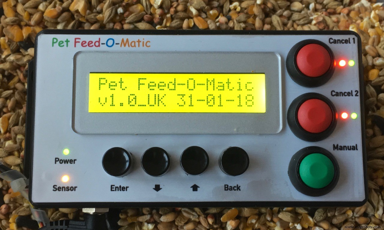
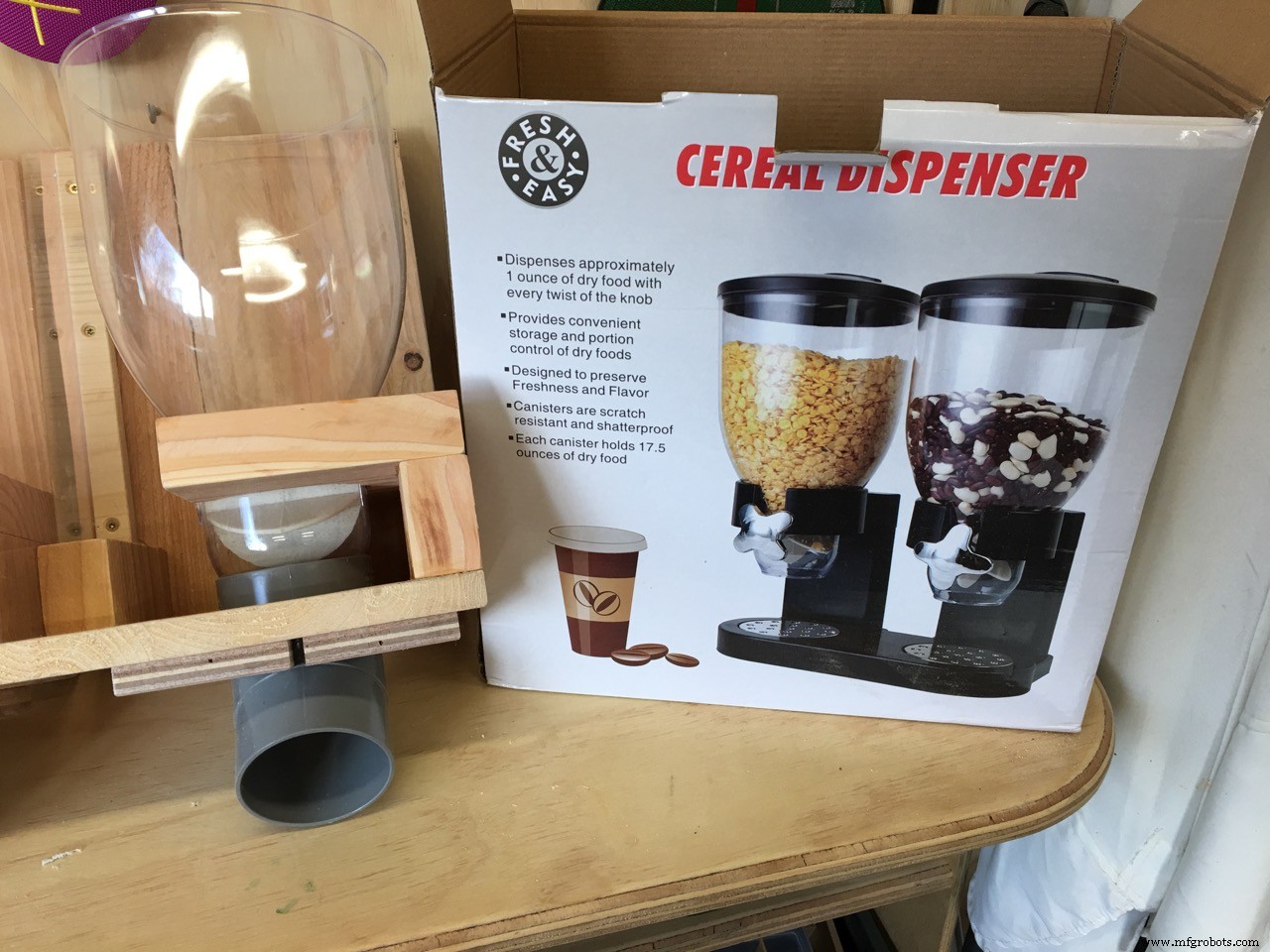
- 1x Cereal dispenser (cheap on Ebay)
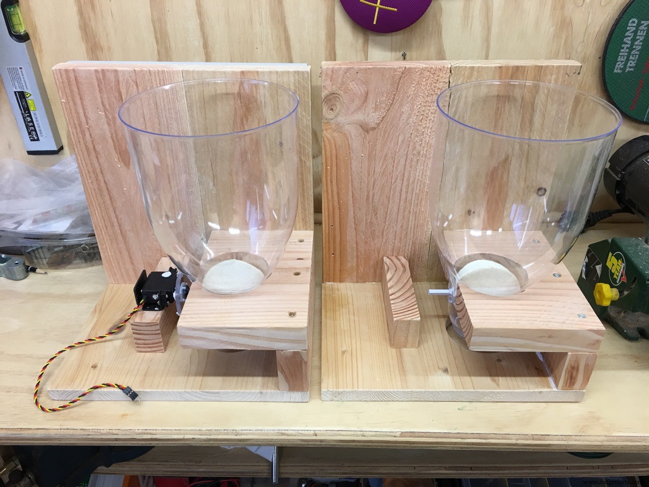
- some (scrap) wood to build the cereal dispenser mount
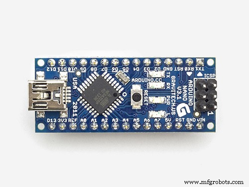
- 1x Arduino Uno
- 1x I2C DS3231 (extremely accurate) or DS1307 Real Time Clock
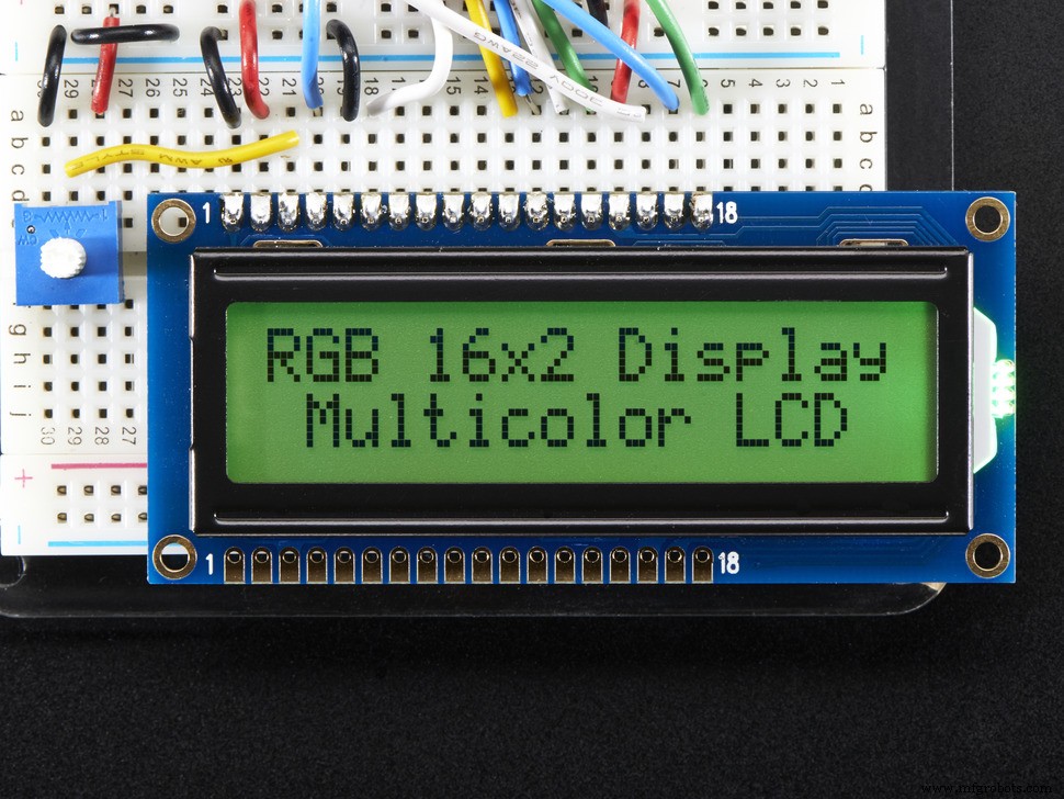
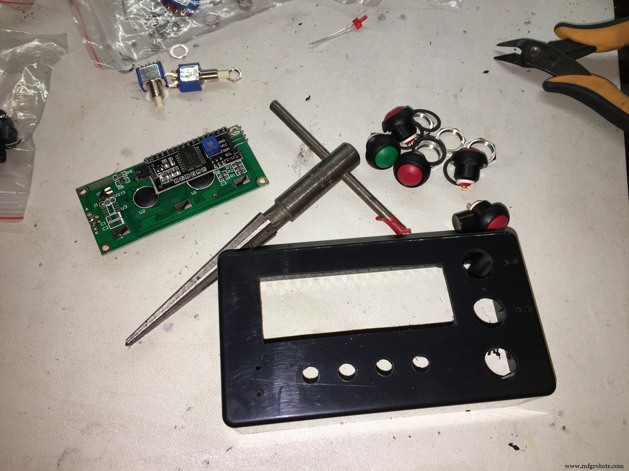
- 1x LCD display 16 characters / 2 lines
- 1x I2C backpack for the LCD display
- 1x Continues rotation Servo (buy a good one!)
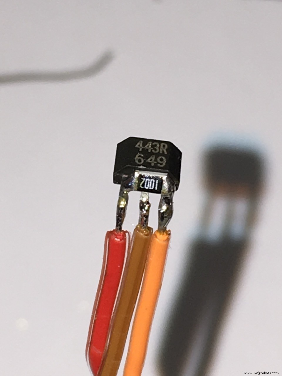
- 1x Honeywell SS443R Unipolar Hall sensor
- 1x 12Volts/1 Amp external power supply (wall wart)
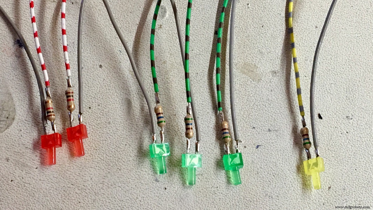
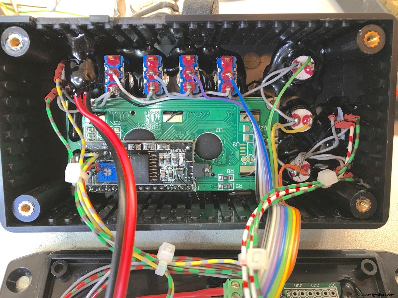
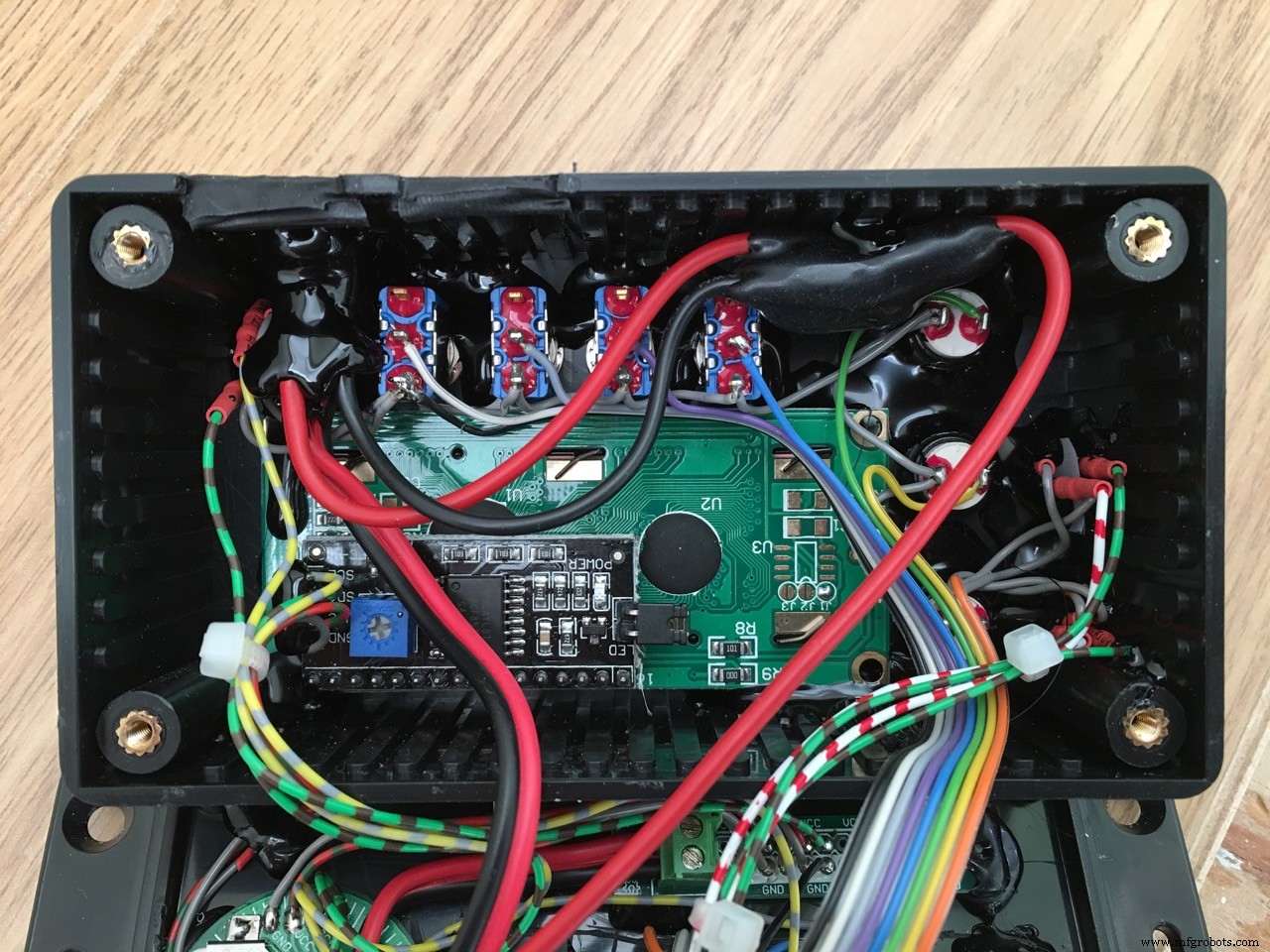
- 7x Push Buttons - Momentary
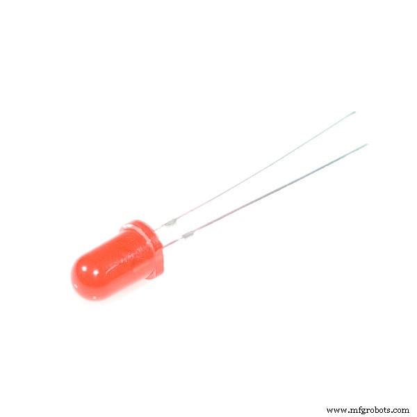
- 6x LED (2x RED, 3x GREEN, 1 YELLOW)
- 2x resistor 1KΩ (for the red led’s)
- 4x resistor 560Ω (for the green and yellow led’s)
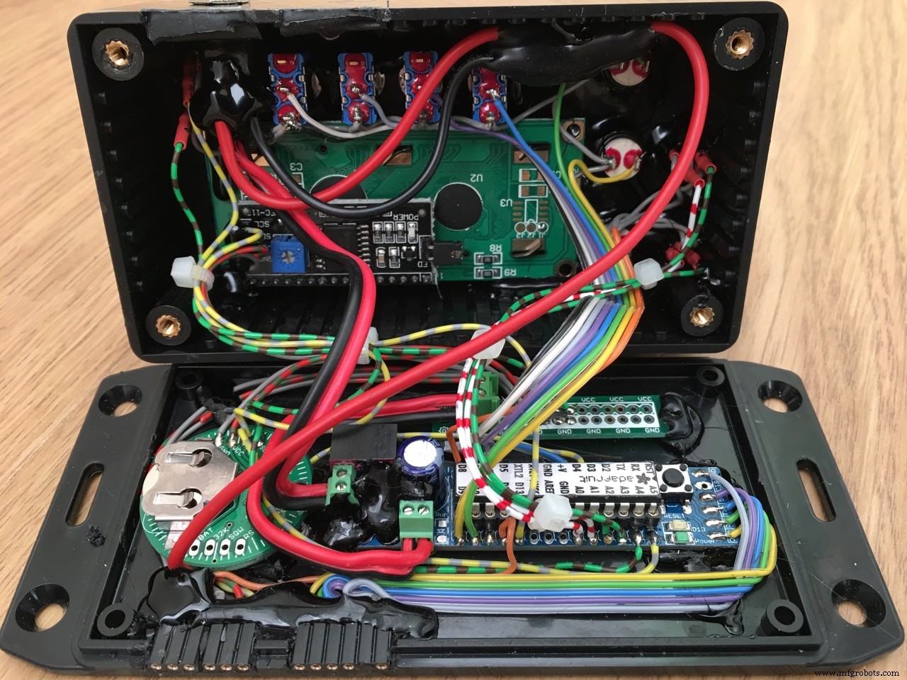
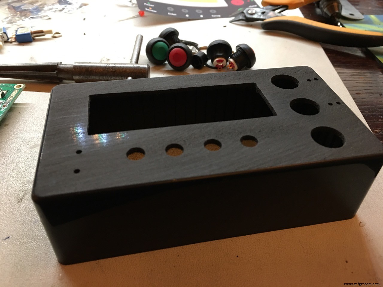
- 1x enclosure for the electronics
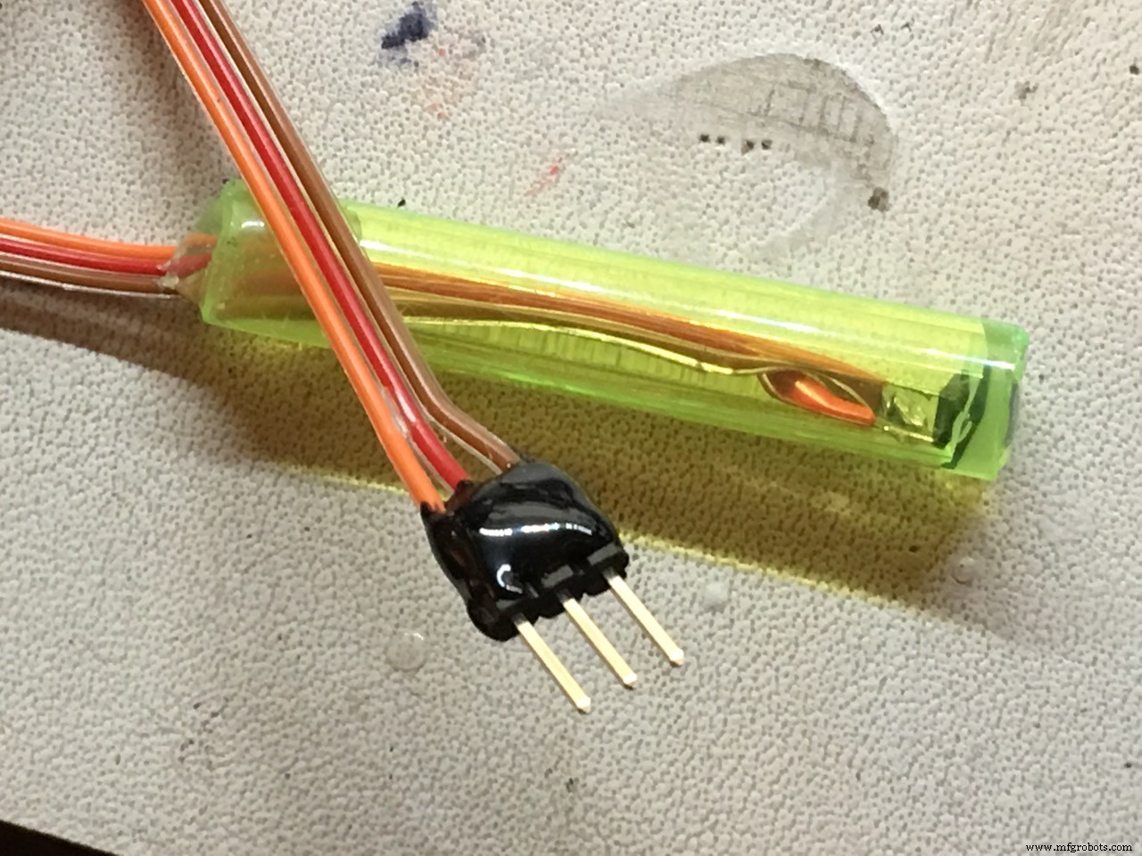
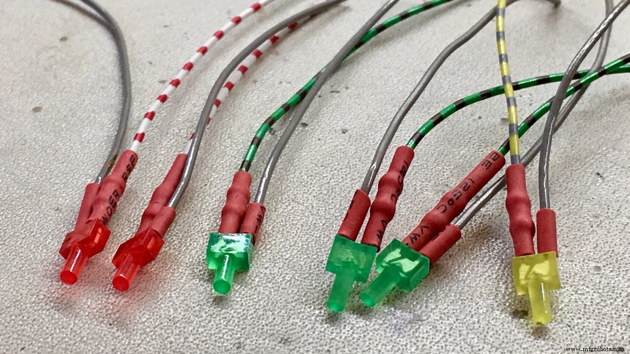
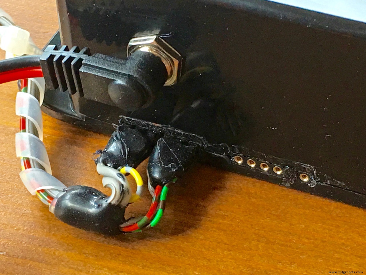
- power plug female and connectors to connect the external servo and hall sensor
- lots and lots of HOT GLUE.
It is best to use a higher voltage for the servo if possible. More power! My HSR-2645CRH Servo can take 7,4 Volts so if you also want to do this you need:
- Perf board
- LM317T Variable voltage regulator
- 3 resistors to set the output voltage (1KΩ, 150kΩ and 4K7)
- 2 polarized capacitors (220µF, 10µF)
- heat sink not needed, the servo will rotate1-2 only seconds each day ;)
Online you can find many LM317 calculators.
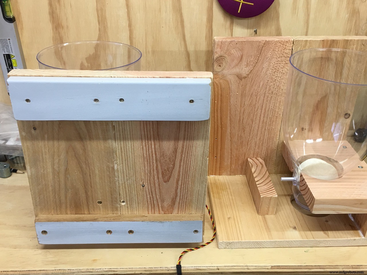
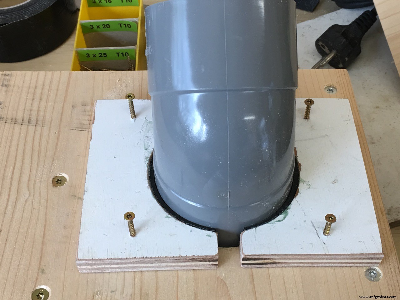
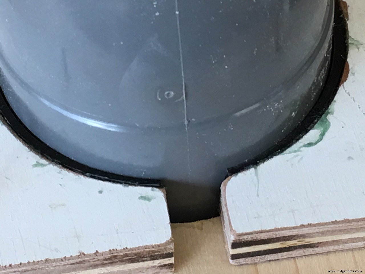
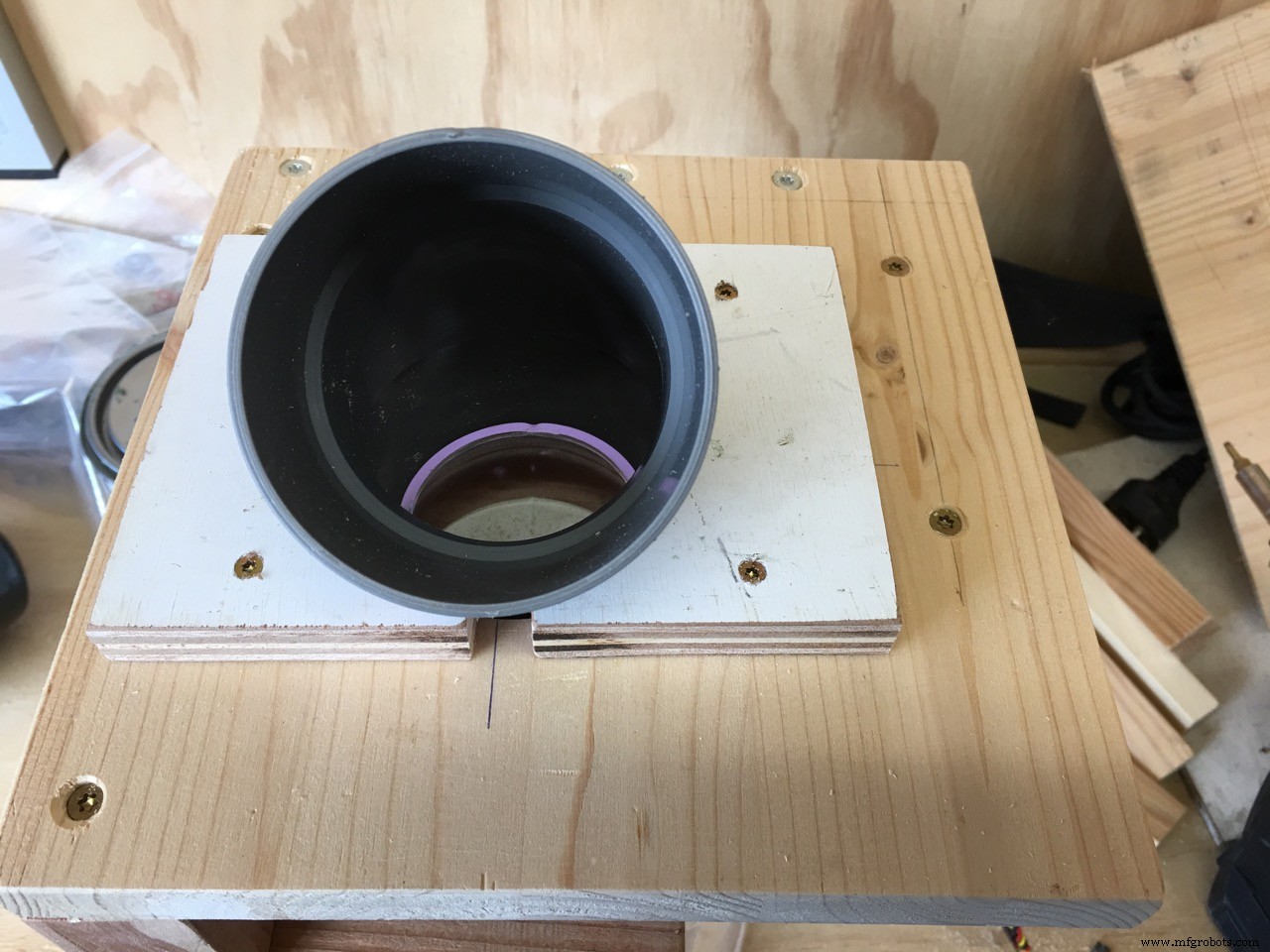
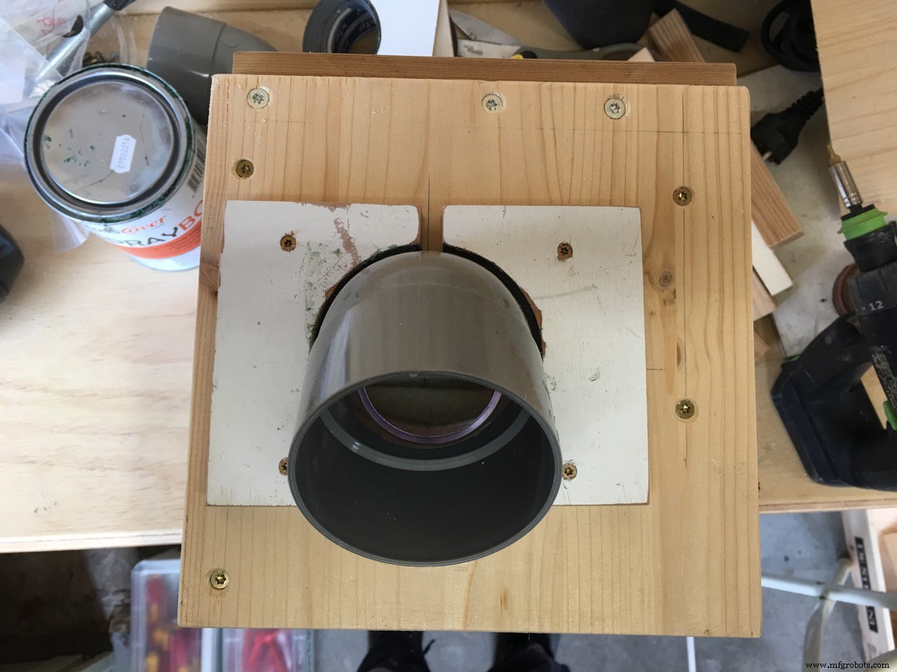
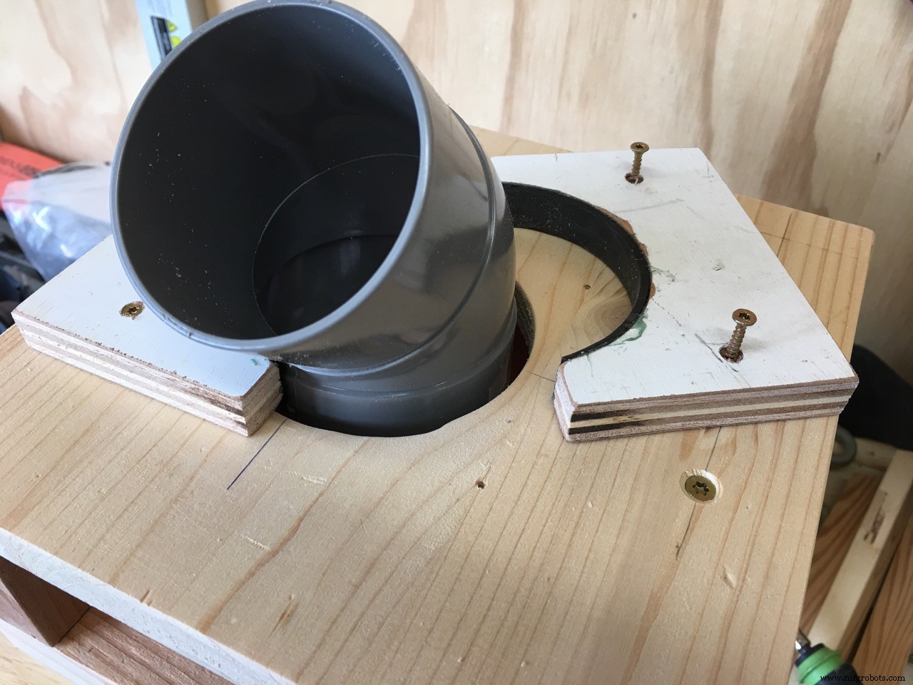
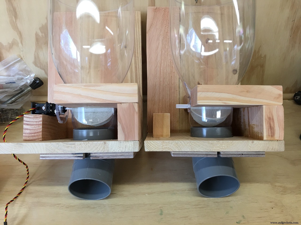
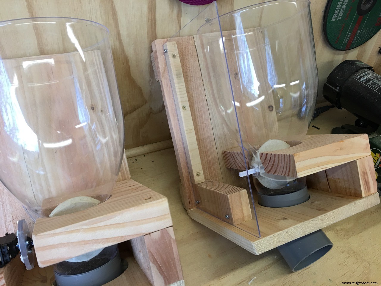
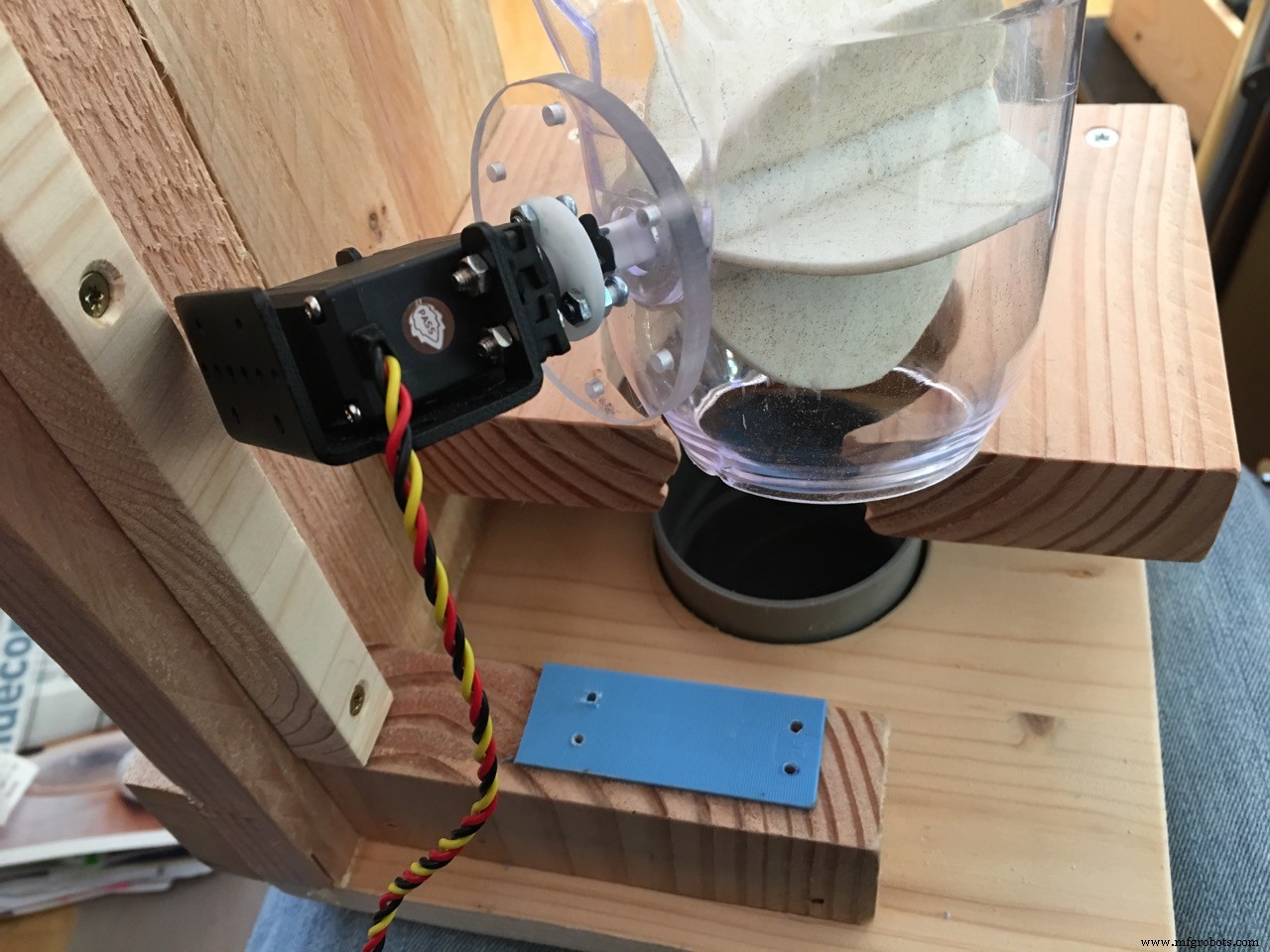
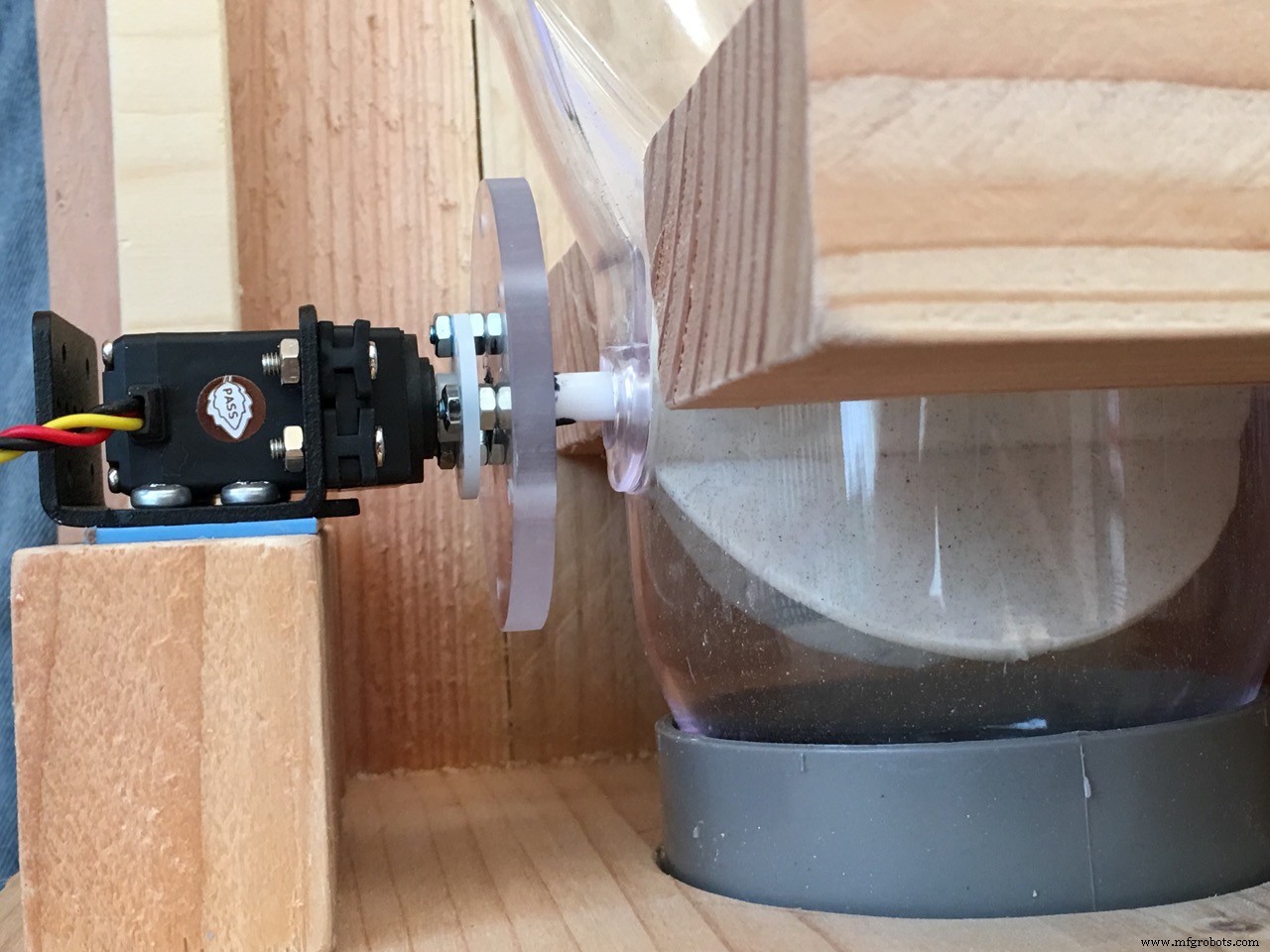
The pet feed containerThe cheapest and easiest to use are the cereal dispensers you can find in many stores and on Ebay. I bought a dual cereal dispenser on Ebay for 15 euro's including shipment (UK to The Netherlands)
The challenge was to make a mount for the feeder and looking around on the internet did not help me much so I looked around in my shed and found some beautiful pieces of Cedar wood.
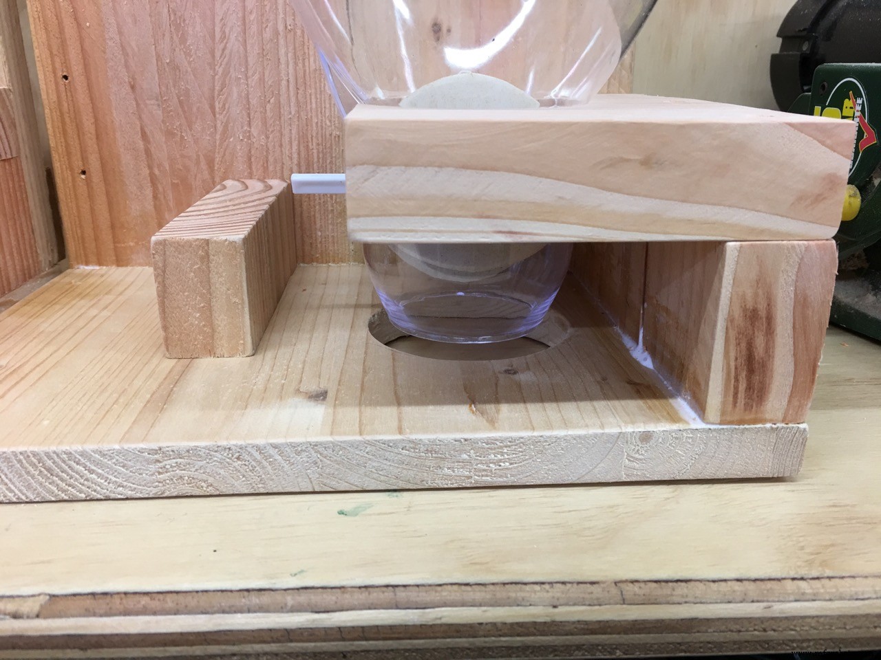
The wood holding the plastic cereal dispenser is 3 cm thick so no wobbling! You need to be sure the hole (my feeder base is 86mm) is tight so measure before drilling! Better to drill a smaller hole and shape it a bit than a hole which is too big.
Look at the photo's to get the idea why and how it fits together.
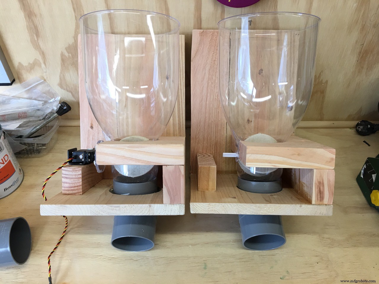
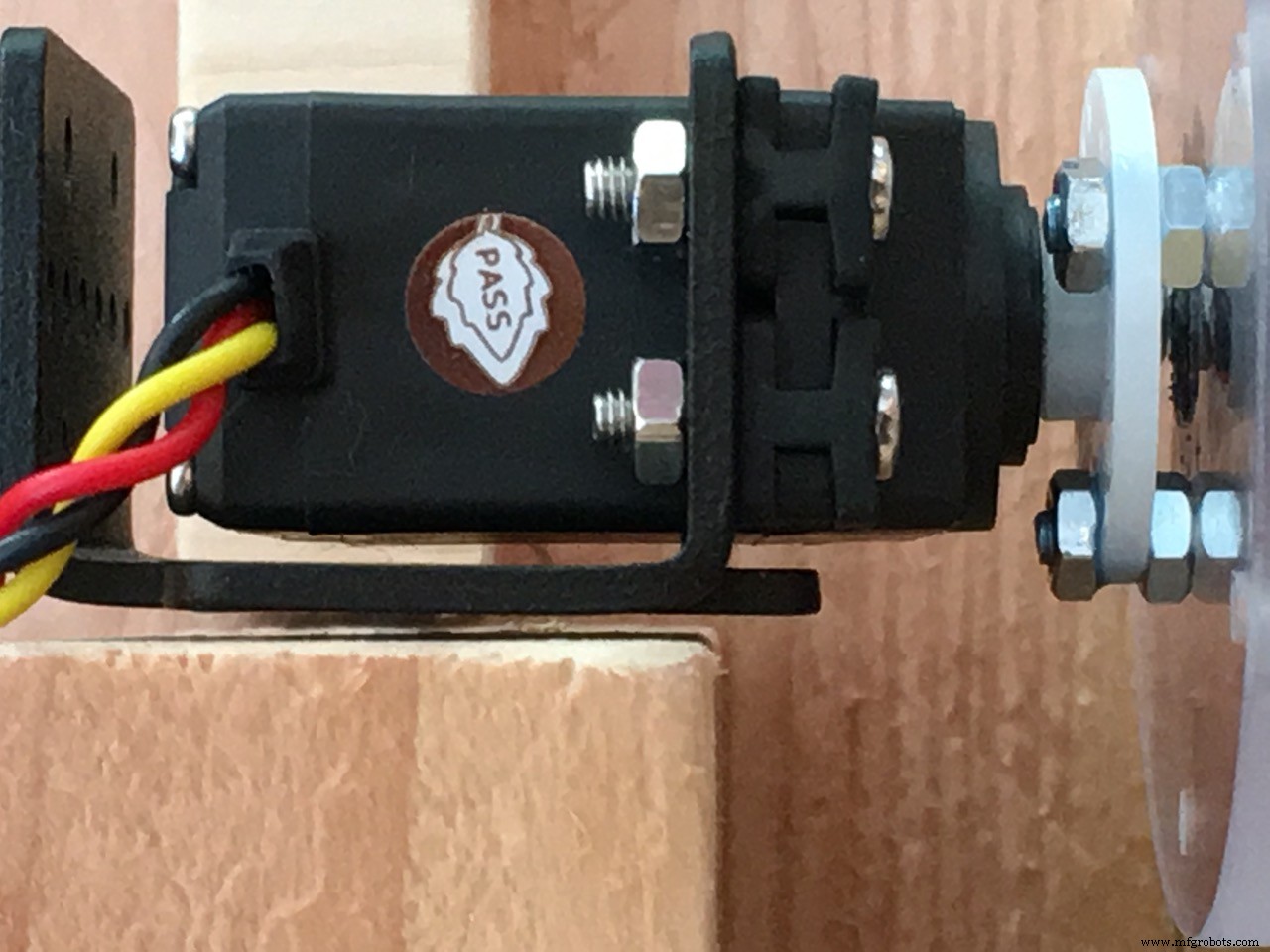
Be sure to buy a good servo. First I bought a MG996R servo which I modified for continous rotation but that was a waste of money... Then I got quality ones, in my case the HSR-2645CRH Servo
It HAS TO BE a continuous rotation model!! Do not attempt to modify a normal servo as I did. It performed not nearly good enough and when stopping, it was not immediate.
video of the servo trial: click HERE
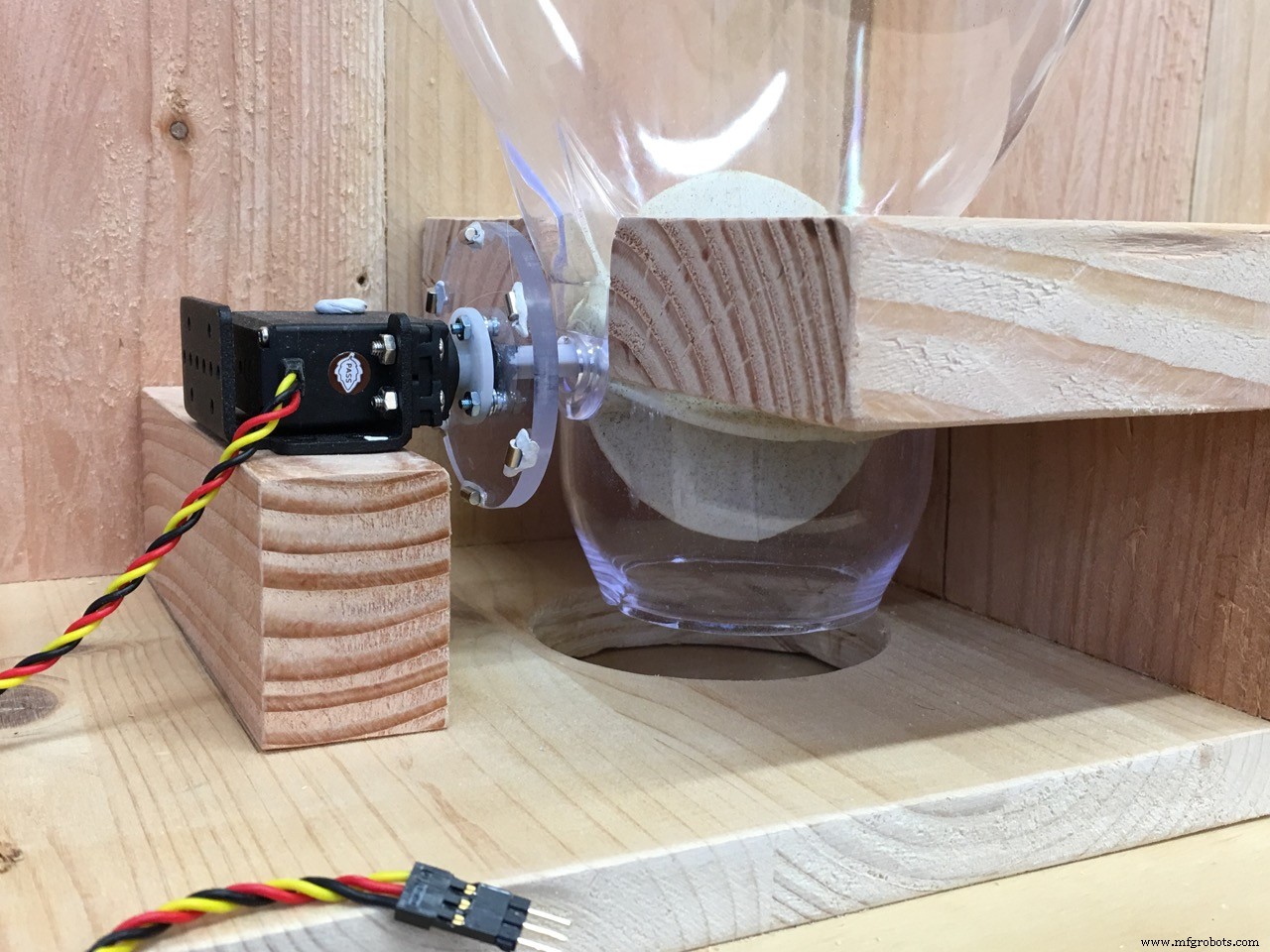
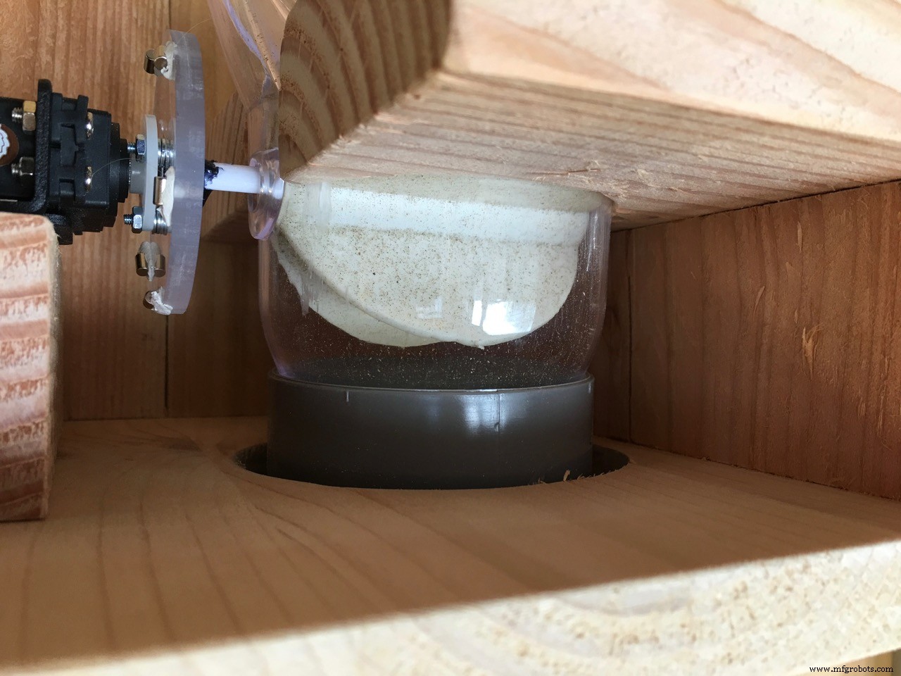
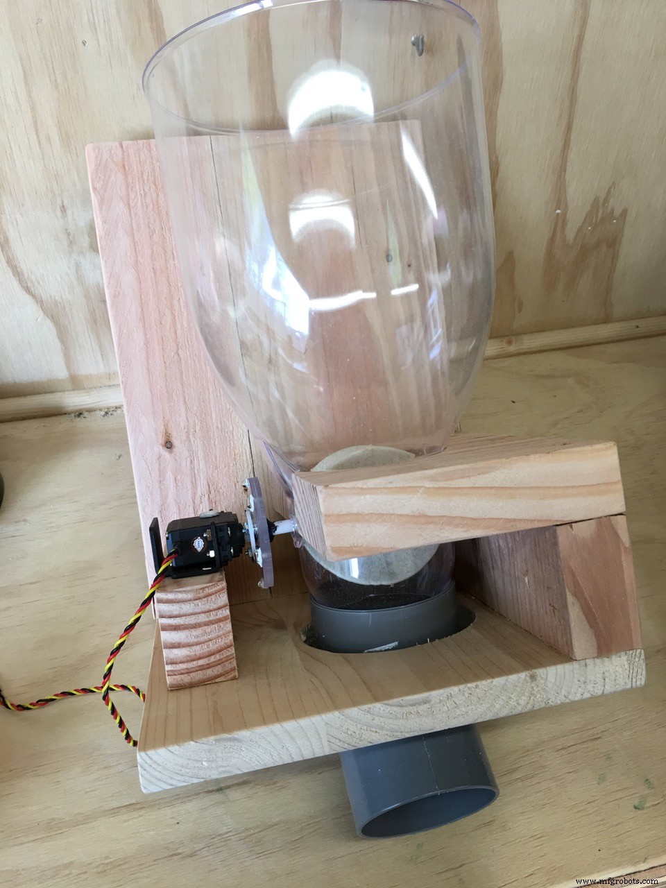
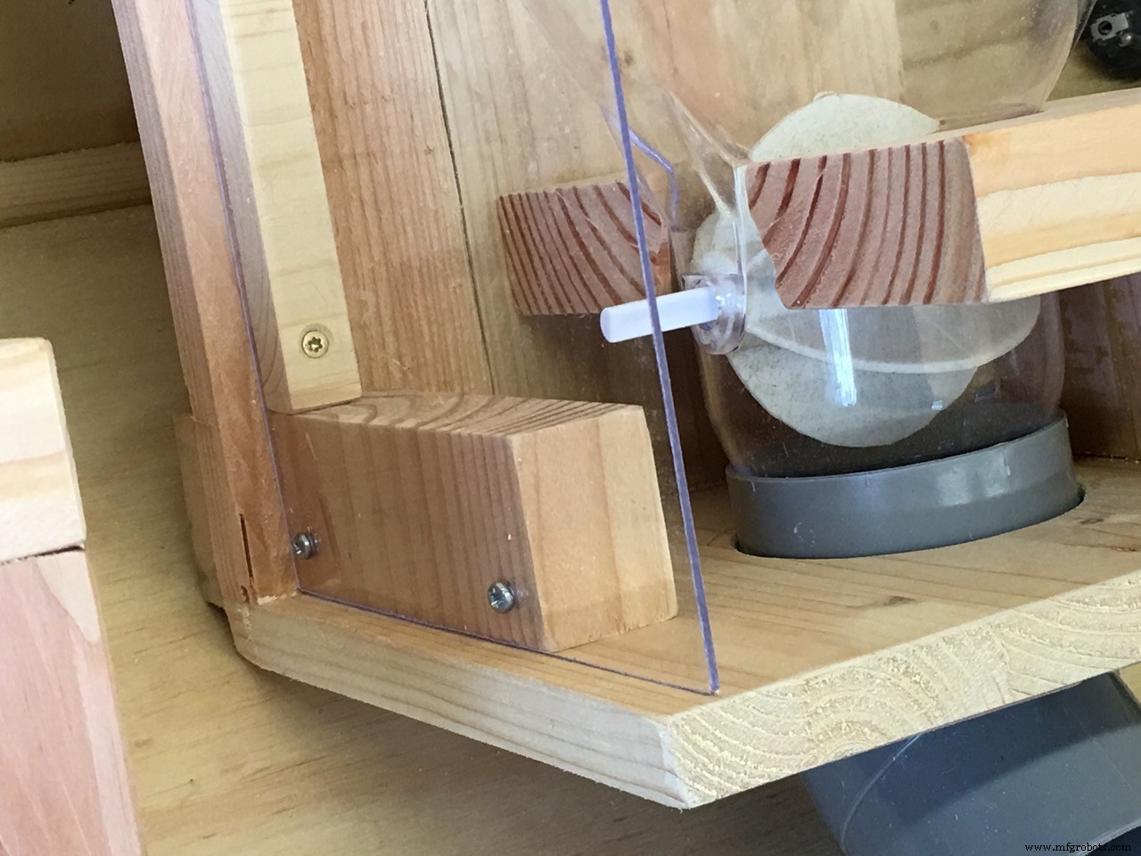
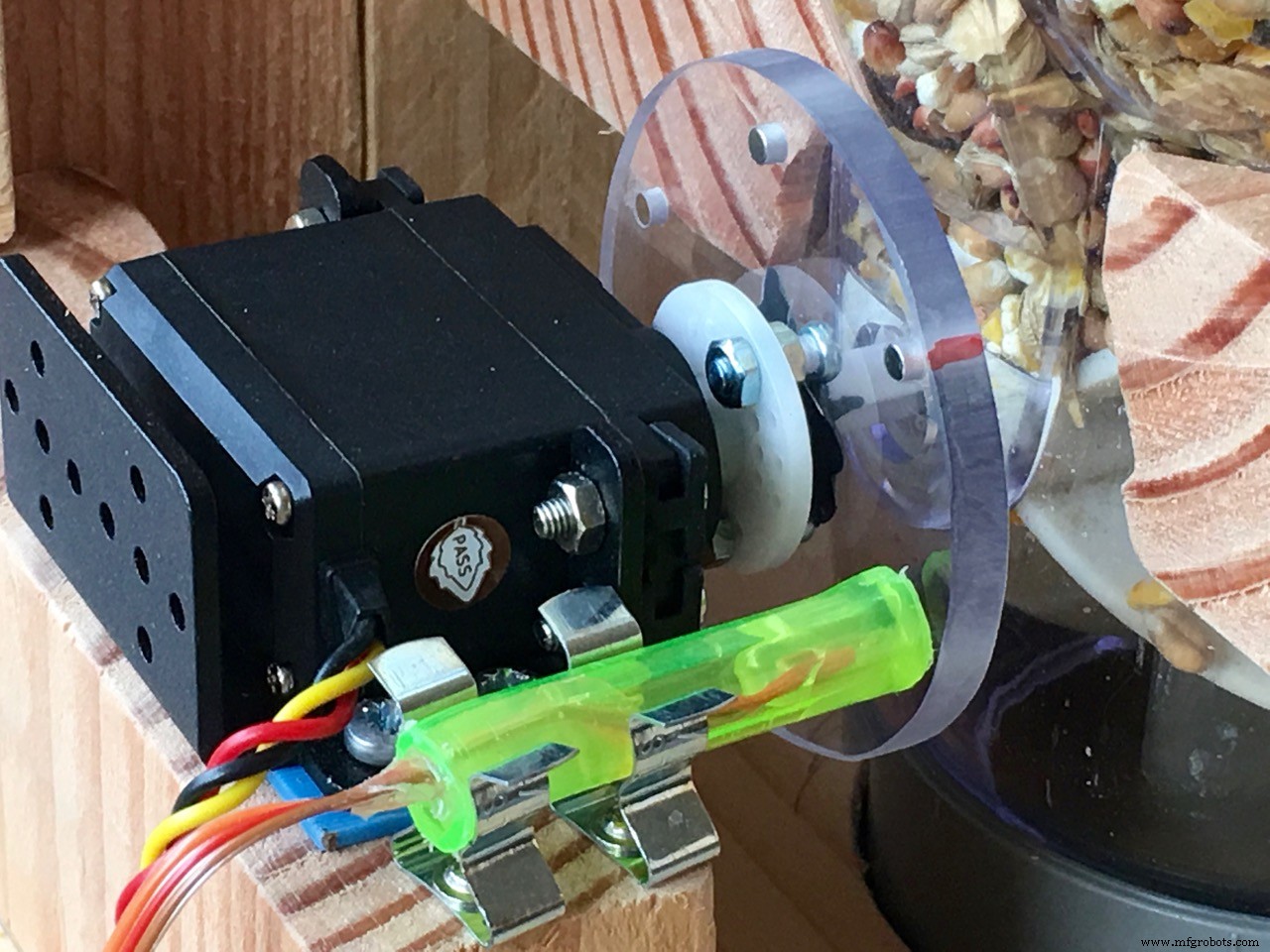
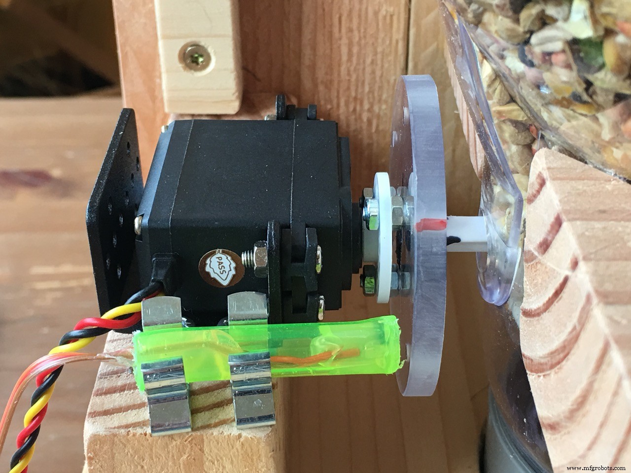
The Servo connection to the dispenser paddle wheel
So now was the question: how to connect the servo to the feeder paddle wheel? It seemed at first the hardest part of the project but it was in fact very simpel.
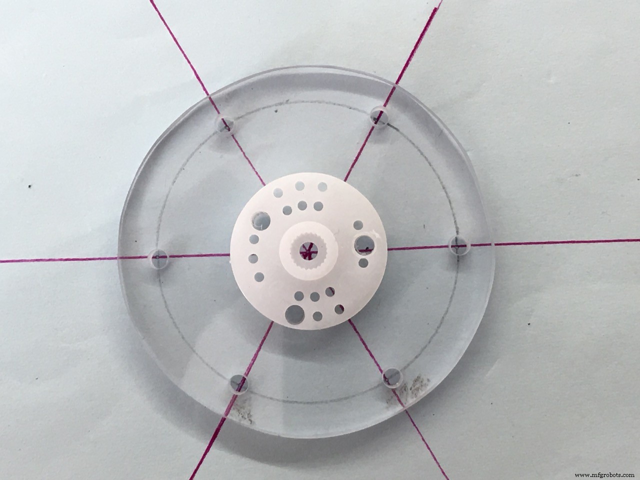
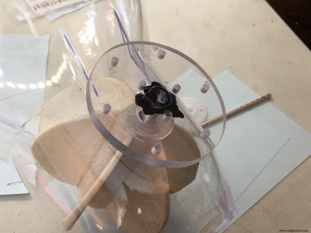
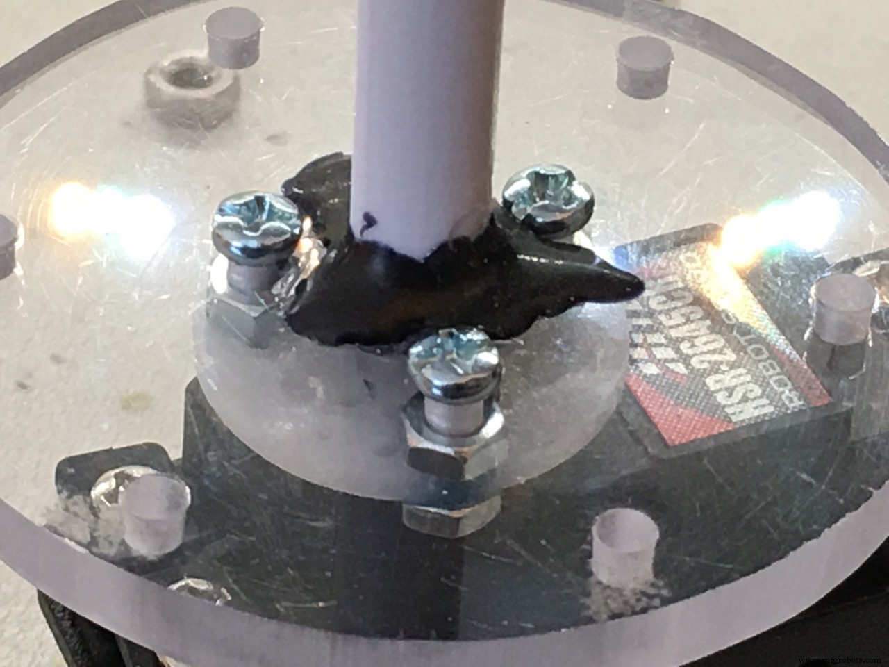
I took a piece of 5mm Polycarbonate and with a fretsaw I cut out a round disc of about 6 cm's. In the center I drilled a hole of 8 mm (the thickness of the feeder axis. This plastic axis is removable from the paddle wheel)
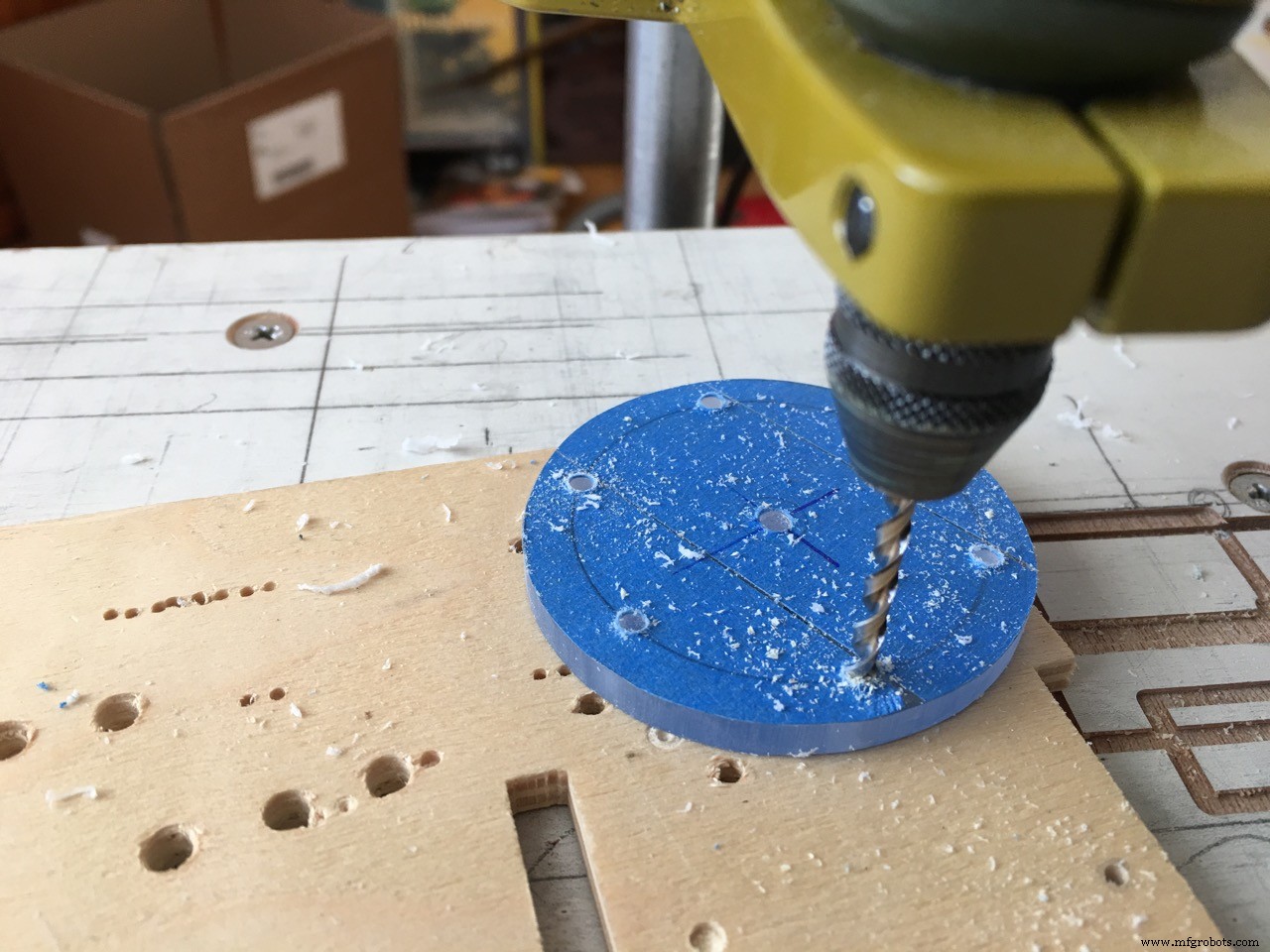
At the outside I drilles 6 holes of 3 mm, the thickness of the magnets. These are used to give the Arduino feedback about the position of the feeder peddle wheel.
Because the paddle wheel had 6 rubber paddles I used 6 magnets and divide them around the edge of the polycarbonate disc. 360 degrees divided by 6 is 60 degrees. The rod magnets will fit in snugly.
The hall sensor will detect each of the 6 magnets so we can use that information to precisely position and stop the paddle wheel. The servo stop delay time variable is used to add a delay after feeding, before stopping the servo. So with this delay you can tweak the exact position of the paddle wheel. This is important because if the 'stop' position is wrong, the feed will not exit the paddle wheel completely. Also the position of the hall sensor may be different in your case. Tweaking the servo stop delay variable time will solve this.
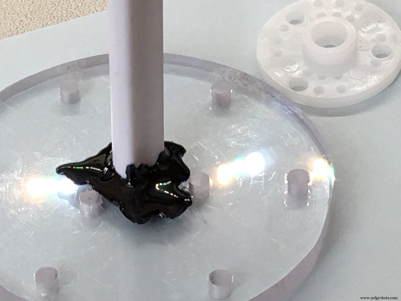
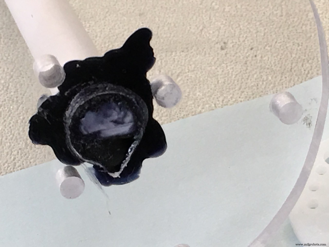
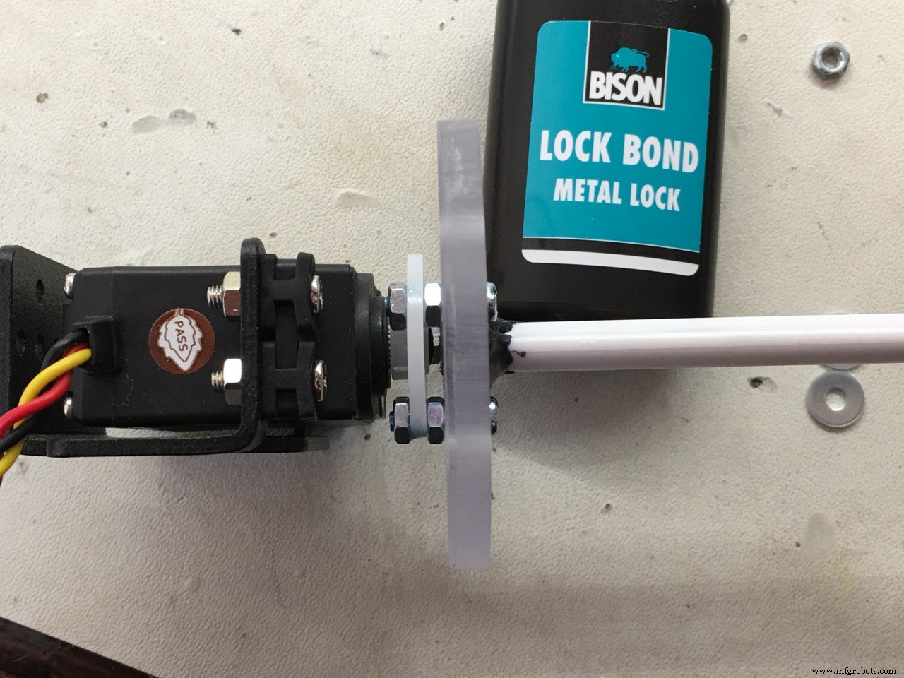
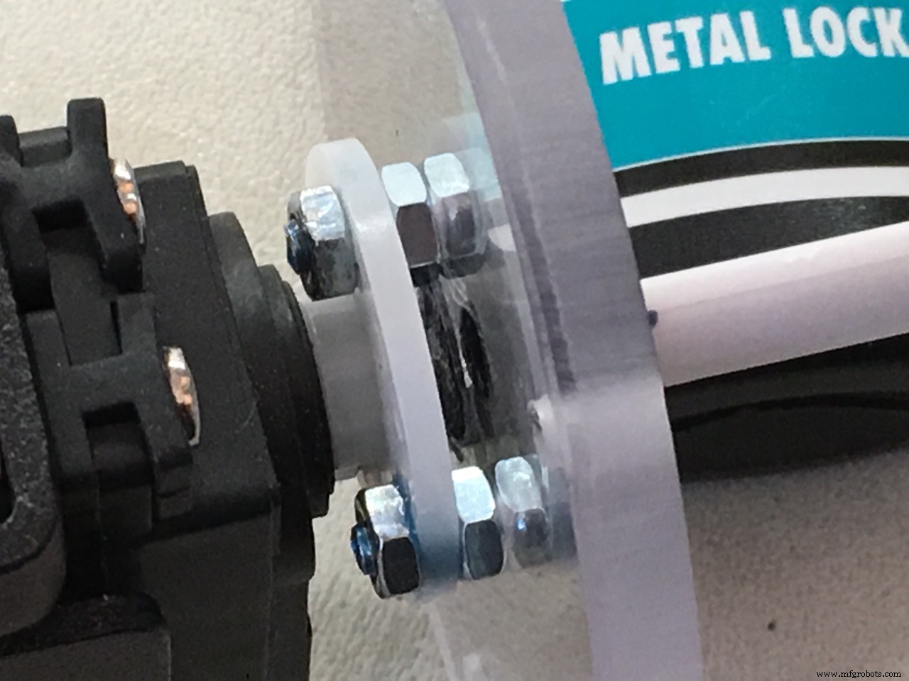
Now we can glue the paddle wheel axis into the polycarbonate disc.
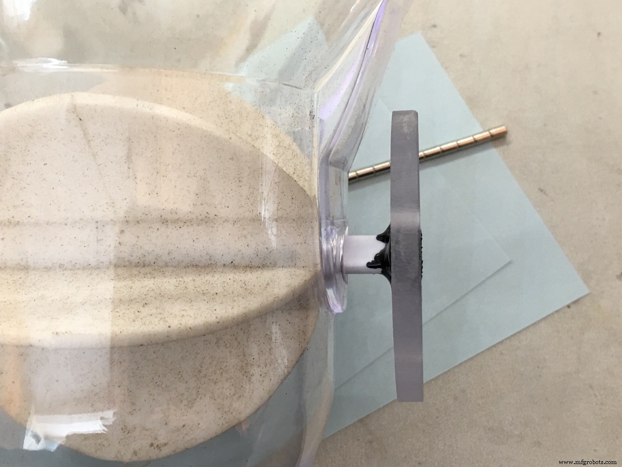
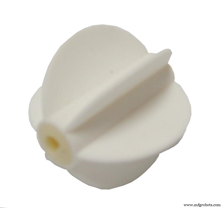
The white round servo horn is bolted on the polycarbonate disc with 3 M3 bolts. use some extra nuts as spacers and don't over tighten!
Now the servo is part of the feeder assembly so we can put it in the wooden mount and measure how tall the wood piece has to be under the servo.
The hall sensor I used is of the UNIPOLAR type. It will give a LOW output if a magnet is near and DOES NOT need the reverse polarity of the magnet to reset the output to HIGH again. So use a Unipolar hall sensor, much easier.
!!! The hall sensor needs a 10KΩ pull up resistor.
I fitted a 0805 SMD resistor right on top of the hall sensor but you can do it your way. Don't forget this resistor!
Then I took an old ballpoint pen and used the plastic as a holder for the sensor.
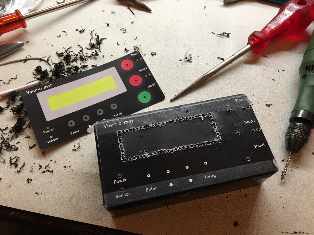
I used a Hammond ABS housing with flange. 120 x 65 x 40 mm

for the external connections I used female precision socket connectors, not the cheap chinese ones. I use these a lot in all my projects. Nothing worse than bad connections causing (hard to find) faillures.
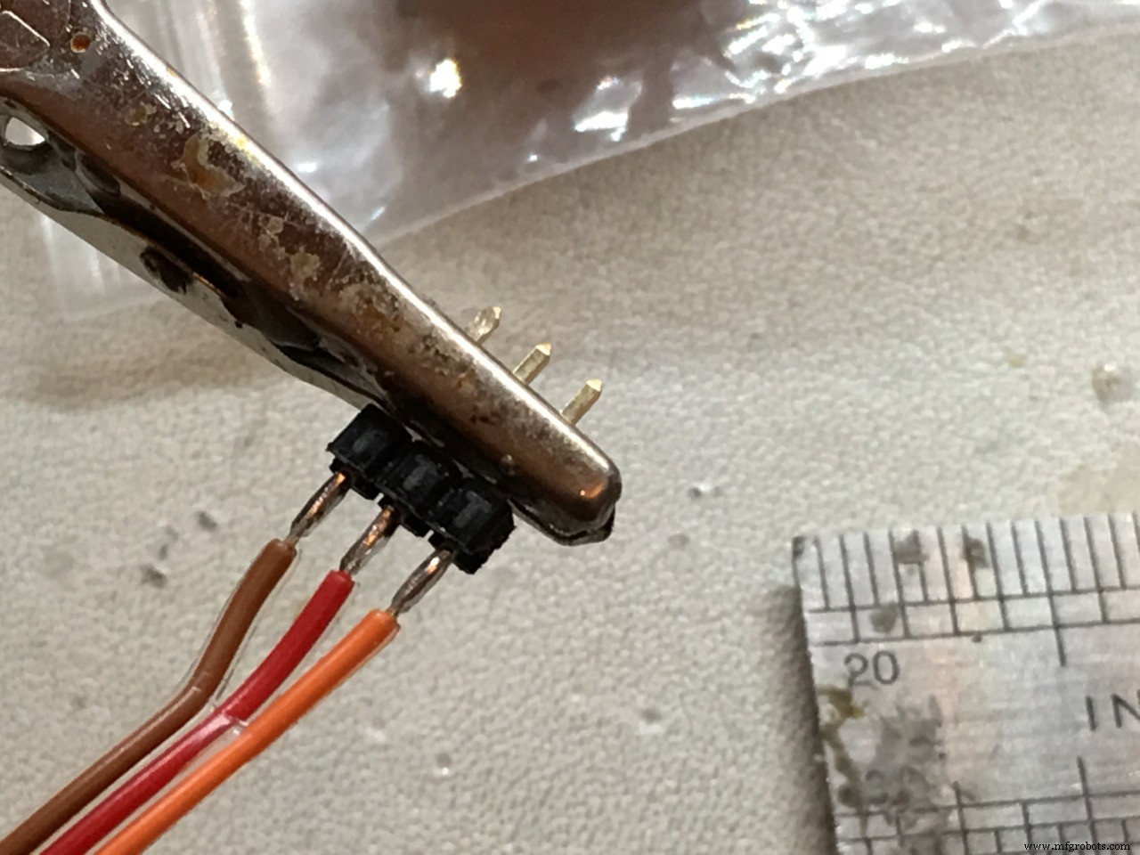
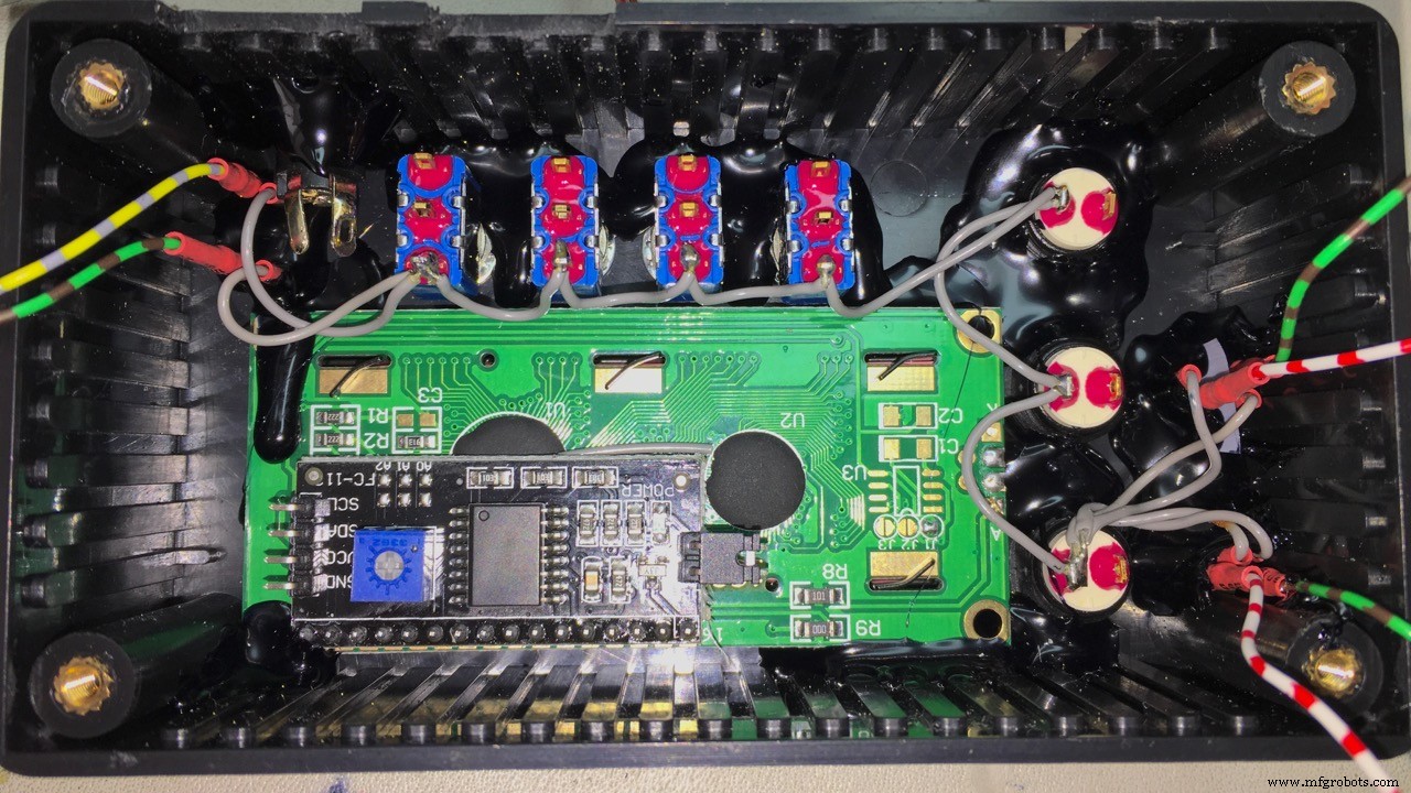
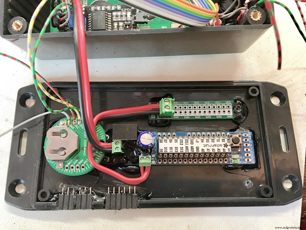
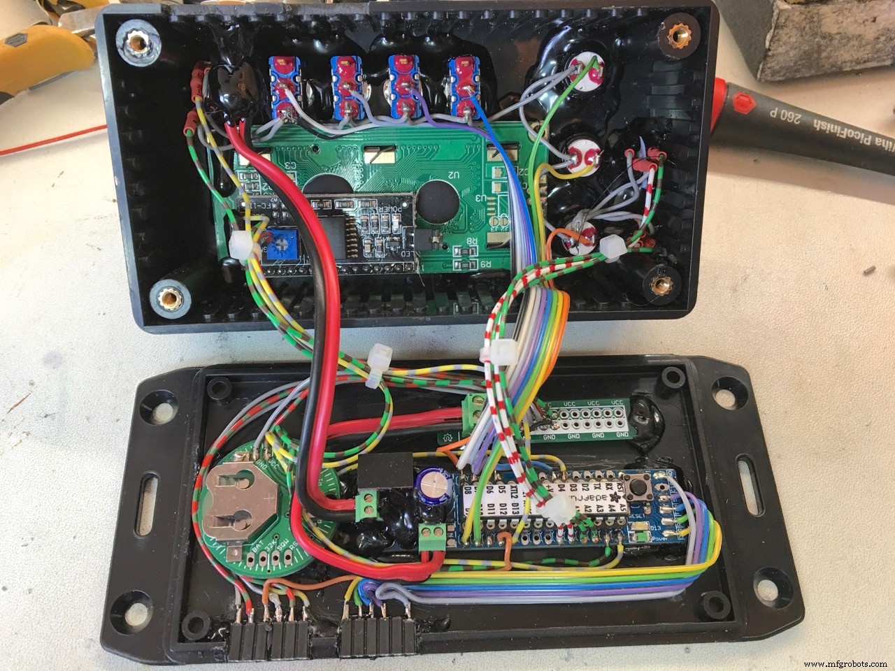
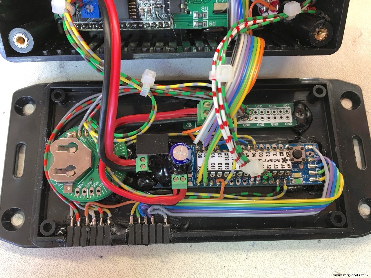

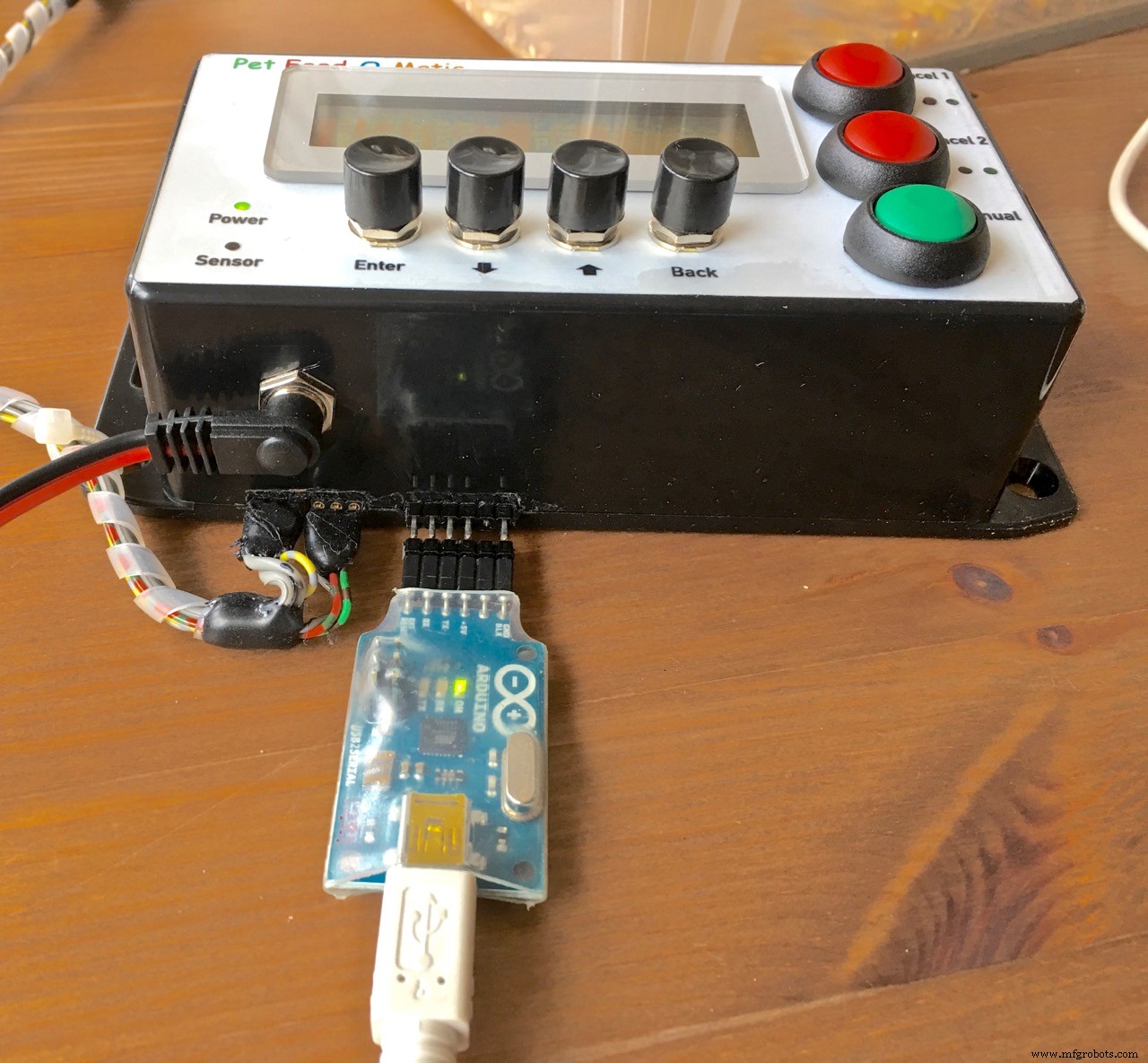
To make programming the Arduino easier, I have an external FTDI connection:
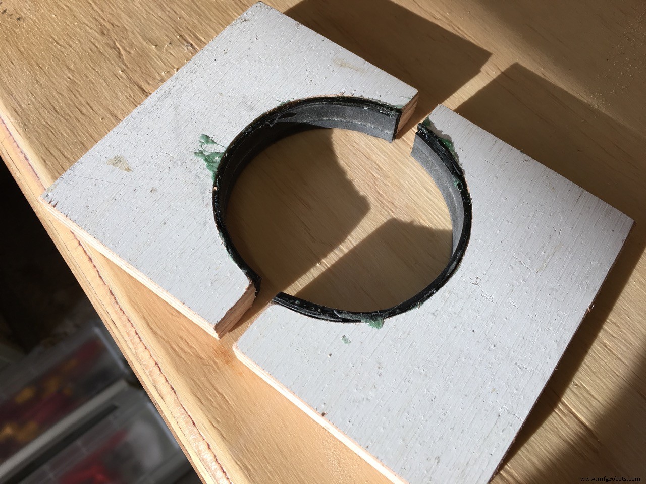
I tried a lot of way to make a cheap and good looking front panel...
First I used Mod Podge to glue a paper laserprint on the front of the housing and cover it with more Mod Podge. --> FAIL
Then I tried a clear varnish, based on polyurethan acrylate dispersion. Very durable and strong when dried. I glued the paper very well on the housing and varnishing the upper side of the front panel print looked very good BUT it would not adhere to the laserprinter toner parts of the print. --> FAIL
After that, I took the laser print of the front panel and only laminated the top with laminating pcv. very nice finish, protecting the front and lifting the colors beautifully. Then again, I glued the laminated paper on the housing with the varnish. My idea was that the varnish would permeate the paper making it water resistant. But because I used thick paper that did not work and making it wet to test water resistance, the paper curled off the housing. --> PARTLY FAIL, to be investigated further.
Another attemp: I bought special aluminium foil, made for laser printing. 2,25 euro's per sheet. The result was great but I wanted to protect the toner with a special clear foil. That was no succes because I could not get rid of the imperfections as seen on photo 1:
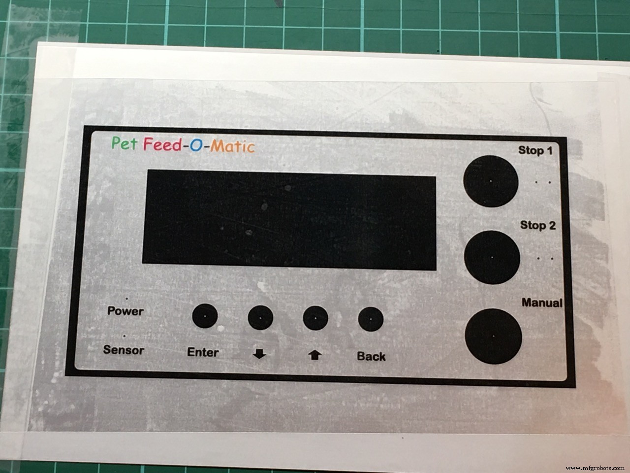
Then another attempt to protect with the clear varnish, It made the alu foil very high gloss! BUT... again, the varnish would not adhere to the toner so I gave up on the varnish permanently...
FINALLY... I used the foil print without protection... It will show vinger prints when handled often (look under the BACK button of the photo at the top of this page, housing in the chicken feed) so not ideal but still good enough for me.
More photo's are not allowed apparently so...
That's all folks... have fun!
Code
- Pet Feed-O-Matic v 1.1 - 20-02-2018
Pet Feed-O-Matic v 1.1 - 20-02-2018Arduino
v 1.1: pressing the Cancel1 or 2 buttons will show a explanation// c++ stuff...
//#include <Arduino.h>
//#line 1
//#line 1 "/Users/Erik/Documents/PlatformIO/Projects/180202-151127-uno/src/Pet_Feeder_1_1_ENG.cpp"
/*
_ _
/\ | | (_)
/ \ _ __ __| |_ _ _ _ __ ___
/ /\ \ | '__/ _` | | | | | '_ \ / _ \
/ ____ \| | | (_| | |_| | | | | | (_) |
/_/ \_\_| \__,_|\__,_|_|_| |_|\___/
_____ _ ______ _
| __ \ | | | ____| | |
| |__) |__| |_ | |__ ___ ___ __| | ___ _ __
| ___/ _ \ __| | __/ _ \/ _ \/ _` |/ _ \ '__|
| | | __/ |_ | | | __/ __/ (_| | __/ |
|_| \___|\__| |_| \___|\___|\__,_|\___|_|
Erik de Ruiter
-----------------------------------------------------------------------------
To do:
- remote feeding?
- feeder stop delay as menu editable item
last change:
dinsdag 20 februari 2018 - 17:20:28
FEATURES:
- *Accurate portions* each time! (by using a Hall sensor)
- Two feeding times, once a day
- *Extremely* accurate Real Time Clock (Only with genuine DS3231 chip)
- Cancel upcoming feeding individually for both timers with
display and Led indicator. Automatically reset after time has passed.
- Manual feed function (one portion per button press)
- Adjustable portions for each of the two feeding times (1-9 portions)
- Overview of all set parameters in the main screen
- Easy to navigate menu system
- LED indication if feeding was successful
- LCD backlight timer (off after 30 sec, on with any button press)
- Backup in the event of a failing Hall sensor
- Hass sensor LED will blink until midnight if the Hall sensor has failed
- Time and other settings are safely stored in EEPROM
WEBSITES:
LCD HD44780 character generator website to make your own lcd symbols
https://omerk.github.io/lcdchargen/
Arduino sketch Large letter comment generator
http://patorjk.com/software/taag/#p=display&c=c%2B%2B&f=Big&t=Comment
Revisions:
zondag 28 januari 2018 - 20:17:10
*/
////////////////////////////////////////////////////////////////////////////////
// USER CHANGEABLE VARIABLES
////////////////////////////////////////////////////////////////////////////////
// used for the Hall sensor fail backup function.
// the interval time should be somewhat larger than one 60 degree
// turn of the feeder (one portion)
#define HALL_SENSOR_BACKUP_VALUE 300
// delay before stopping the feeder servo after feeding. This way you can
// let the rotating peddle wheel stop at the right position
#define FEEDER_STOP_DELAY 100
// lcd backlight on time after pressing a button
#define LCD_BACKLIGHT_ON_TIME 30000
// exit menu without save after amanout of time set here in ms
#define MENU_TIMEOUT_VALUE 7000
////////////////////////////////////////////////////////////////////////////////
// https:// github.com/fdebrabander/Arduino-LiquidCrystal-I2C-library
#include <LiquidCrystal_I2C.h>
// https:// github.com/JChristensen/Button
#include <Button.h>
// http:// github.com/JChristensen/DS3232RTC
#include <DS3232RTC.h>
// http:// www.arduino.cc/playground/Code/Time
#include <Time.h>
// http:// arduino.cc/en/Reference/Wire (included with Arduino IDE)
#include <Wire.h>
#include <EEPROM.h>
// CONNECTIONS:
//
// LCD (I2C module):
// SCL - A5
// SDA - A4
// VCC
// GND
// interrupt hal sensor pin
#define HALL_SENSOR_PIN 3
#define BUTTON_BACK_PIN 4
#define BUTTON_UP_PIN 5
#define BUTTON_DOWN_PIN 6
#define BUTTON_SELECT_PIN 7
#define BUTTON_CANCEL1_PIN 8
#define BUTTON_CANCEL2_PIN 9
#define BUTTON_MANUAL_PIN 10
#define LED_CANCEL1_PIN A0
#define LED_CANCEL2_PIN A1
#define LED_SUCCESS1_PIN A2
#define LED_SUCCESS2_PIN A3
// feeder Servo output Pin
#define SERVO_OUTPUT_PIN 12
// Hall sensor input Pin
#define LED_HALL_SENSOR_PIN 13
// address LCD(16x2) 0x27 or 0x3F
LiquidCrystal_I2C lcd(0x3F, 16, 2);
// define button library settings
// A debounce time of 20 milliseconds usually works well
// for tactile button switches.
#define DEBOUNCE_MS 20
// ms required before repeating on long press
#define REPEAT_FIRST 1000
// repeat interval for long press
#define REPEAT_INCR 200
// To keep things simple, we use the Arduino's internal pullup resistor.
#define PULLUP true
#define INVERT true
// Declare the buttons
Button buttonSelect (BUTTON_SELECT_PIN, PULLUP, INVERT, DEBOUNCE_MS);
Button buttonUp (BUTTON_UP_PIN, PULLUP, INVERT, DEBOUNCE_MS);
Button buttonDown (BUTTON_DOWN_PIN, PULLUP, INVERT, DEBOUNCE_MS);
Button buttonBack (BUTTON_BACK_PIN, PULLUP, INVERT, DEBOUNCE_MS);
Button buttonCancel1 (BUTTON_CANCEL1_PIN, PULLUP, INVERT, DEBOUNCE_MS);
Button buttonCancel2 (BUTTON_CANCEL2_PIN, PULLUP, INVERT, DEBOUNCE_MS);
Button buttonManual (BUTTON_MANUAL_PIN, PULLUP, INVERT, DEBOUNCE_MS);
// The number that is adjusted
int count;
// Previous value of count (initialized to ensure it's different when
// the sketch starts)
int lastCount = -1;
// A variable time that is used to drive the repeats for long presses
unsigned long rpt = REPEAT_FIRST;
// used for the menu time-out
unsigned long timeoutValue = 0;
// manual cancel feeding times variables
boolean manualCancelFeed1 = false;
boolean manualCancelFeed2 = false;
// Manaual feed option
boolean manualFeed = false;
// Feed amount (in portions)
int feedAmount1 = 1;
int feedAmount2 = 1;
bool feederSuccess = false;
// feeder portions
int portions = 0;
int turns = 0;
// input actions
enum {btnSELECT, btnUP, btnDOWN, btnBACK, btnCANCEL1, btnCANCEL2, btnMANUAL, trigTIMEOUT};
// States of the Finite State Machine (FSM)
enum STATES
{
MAIN,
MENU_EDIT_FEEDTIME1,
MENU_EDIT_FEEDTIME2,
MENU_EDIT_FEEDAMOUNT,
MENU_EDIT_TIME,
MENU_EDIT_DATE,
MENU_EDIT_SETTINGS,
EDIT_FEED_TIME1_HOUR,
EDIT_FEED_TIME1_MINUTE,
EDIT_FEED_TIME1_ON_OFF,
EDIT_FEED_TIME2_HOUR,
EDIT_FEED_TIME2_MINUTE,
EDIT_FEED_TIME2_ON_OFF,
EDIT_FEED_AMOUNT1,
EDIT_FEED_AMOUNT2,
EDIT_HOUR,
EDIT_MINUTE,
EDIT_DAY,
EDIT_MONTH,
EDIT_YEAR,
EDIT_SERVO_STOP_DELAY,
EDIT_SERVO_BACKUP_DELAY,
};
// Holds the current state of the system
STATES state;
int8_t userInput;
int8_t trigger;
int Second;
int Minute;
int Hour;
int Day;
int Month;
int Year;
int8_t DoW;
String day_of_week;
unsigned char address, data;
int testt = 0;
int feed_time1_hour;
int feed_time1_minute;
bool feed_time1_active = false;
bool alarm1Activated = false;
int feed_time2_hour;
int feed_time2_minute;
bool feed_time2_active = false;
bool alarm2Activated = false;
// used for the blink funtion when editing values
uint32_t blink_interval = 500;
uint32_t blink_previousMillis = 0;
uint32_t blink_currentMillis = 0;
boolean blink_state = false;
// used for the blink funtion when editing values
uint32_t spinningWheel_interval = 170;
uint32_t spinningWheel_previousMillis = 0;
uint32_t spinningWheel_currentMillis = 0;
int spinningWheelSymbol = 0;
// used for the Hall sensor fail backup function
// the interval time should be somewhat larger than one 60 degree
// turn of the feeder (one portion).
uint32_t hallSensorBackup_interval = HALL_SENSOR_BACKUP_VALUE;
uint32_t hallSensorBackup_currentMillis = 0;
boolean hallSensorFail = false;
// used for the lcd backlight timer
uint32_t lcdBacklight_interval = LCD_BACKLIGHT_ON_TIME;
uint32_t lcdBacklight_currentMillis = 0;
boolean RTC_error = true;
boolean long_press_button = false;
// Define custom symbols for the LCD display
byte bell_symbol_Char[8] = {
B00100,
B01110,
B01110,
B01110,
B11111,
B00100,
B00000,
B00000
};
byte inverted_one_Char[8] = {
0b11111,
0b11011,
0b10011,
0b11011,
0b11011,
0b11011,
0b10001,
0b11111
};
byte inverted_two_Char[8] = {
0b11111,
0b11011,
0b10101,
0b11101,
0b11011,
0b10111,
0b10001,
0b11111
};
byte arrow_up_Char[8] = {
0b00100,
0b01110,
0b11111,
0b01110,
0b01110,
0b01110,
0b01110,
0b00000
};
byte arrow_down_Char[8] = {
0b00000,
0b01110,
0b01110,
0b01110,
0b01110,
0b11111,
0b01110,
0b00100
};
byte inverted_p_Char[8] = {
0b11111,
0b10001,
0b10101,
0b10001,
0b10111,
0b10111,
0b11111,
0b00000
};
byte backslash_Char[8] = {
0b00000,
0b10000,
0b01000,
0b00100,
0b00010,
0b00001,
0b00000,
0b00000
};
byte thickDash_Char[8] = {
0b00000,
0b00000,
0b11111,
0b11111,
0b11111,
0b00000,
0b00000,
0b00000
};
volatile boolean hallSensorActivated = false;
// Interrupt 1
void HallSensorIsr()
{
hallSensorActivated = true;
// turn on Hall sensor LED
digitalWrite(LED_HALL_SENSOR_PIN, HIGH);
}
// These lines are needed to make this sketch a C++ file.
// I use it because I edit the code with the Atom
// text editor and the PlatformIO add-on
void HallSensorIsr();
void setup();
void loop();
void change_states();
void check_inputs();
void transition(int trigger);
void check_alarm();
void check_manual_feed();
void display_menu_option_set_feedtime1();
void display_menu_option_set_feedtime2();
void display_menu_option_set_feed_amount();
void display_menu_option_set_time();
void display_menu_option_set_date();
void midnight_reset();
void display_time();
void displayFeedingAmouts();
void displayFeedingTimes();
void set_feedAmount();
void set_time();
void set_date();
void set_feeding1_time();
void set_feeding2_time();
void get_time();
void get_date();
void write_time();
void write_date();
void write_feeding_time1();
void write_feeding_time2();
void write_feedamount();
void get_feedamount();
void get_feed_time1();
void get_feed_time2();
void check_RTC();
byte decToBcd(byte val);
byte bcdToDec(byte val);
void leading_zero(int digits);
void blinkFunction();
void displaySpinningWheel();
void startFeederServo();
void stopFeederServo();
void activateFeeder(int portions);
void check_LcdBacklight();
void lcd_backlight_ON();
void ledsAndLcdDisplayStartup();
void hallSensorCheck();
#line 355
// ******************************************************************************
// SETUP
void setup()
{
// activate the lcd screen
lcd.begin();
// turn lcd backlight on and start backlight off-timer
lcd_backlight_ON();
// start I2C
Wire.begin();
// hall sensor input to detect rotation of the feeder/feed amount output check
pinMode(HALL_SENSOR_PIN, INPUT_PULLUP);
pinMode(LED_HALL_SENSOR_PIN, OUTPUT);
pinMode(SERVO_OUTPUT_PIN, OUTPUT);
pinMode(LED_CANCEL1_PIN, OUTPUT);
pinMode(LED_CANCEL2_PIN, OUTPUT);
pinMode(LED_SUCCESS1_PIN, OUTPUT);
pinMode(LED_SUCCESS2_PIN, OUTPUT);
// set default state of LED's to OFF
digitalWrite(LED_CANCEL1_PIN, LOW);
digitalWrite(LED_CANCEL2_PIN, LOW);
digitalWrite(LED_SUCCESS1_PIN, LOW);
digitalWrite(LED_SUCCESS2_PIN, LOW);
digitalWrite(LED_HALL_SENSOR_PIN, LOW);
lcd.createChar(0, thickDash_Char);
lcd.createChar(1, bell_symbol_Char);
lcd.createChar(2, backslash_Char);
lcd.createChar(3, inverted_p_Char);
lcd.createChar(4, inverted_one_Char);
lcd.createChar(5, inverted_two_Char);
lcd.createChar(6, arrow_up_Char);
lcd.createChar(7, arrow_down_Char);
// set feeder Servo to default state OFF
stopFeederServo();
Wire.begin();
// set RTC as the Syncprovider
setSyncProvider(RTC.get);
// time in sec of resync with RTC
setSyncInterval(60);
// Disable the default square wave of the SQW pin.
RTC.squareWave(SQWAVE_NONE);
// Attach an interrupt on the Hall sensor (when unput turns LOW)
// ever 60 degree turn of the feeder shaft, the hall sensor
// should generate an interrupt
attachInterrupt(INT1, HallSensorIsr, FALLING);
// display test
ledsAndLcdDisplayStartup();
// Initial state of the FSM
state = MAIN;
// read the stored alarm value from the Arduino memory
get_feed_time1();
get_feed_time2();
}// End SETUP
// ******************************************************************************
// LOOP
void loop()
{
// change states of FSM
change_states();
// check inputs (buttons)
check_inputs();
// check if alarm was called
check_alarm();
// check if manual feed was requsted
check_manual_feed();
// at midnight, reset some variables
midnight_reset();
// check connection RTC
check_RTC();
// Check the Hall sensor function
hallSensorCheck();
// check if lcd backlight must be turned off
check_LcdBacklight();
}// End of LOOP
// ******************************************************************************
// ******************************************************************************
// ******************************************************************************
// ******************************************************************************
//******************************************************************************
// Finite State Machine
void change_states()
{
// states
switch (state)
{
//---------------------------------------
case MAIN:
display_time();
displayFeedingAmouts();
displayFeedingTimes();
break;
//---------------------------------------
case MENU_EDIT_FEEDTIME1:
display_menu_option_set_feedtime1();
break;
//---------------------------------------
case MENU_EDIT_FEEDTIME2:
display_menu_option_set_feedtime2();
break;
//---------------------------------------
case MENU_EDIT_FEEDAMOUNT:
display_menu_option_set_feed_amount();
break;
//---------------------------------------
case MENU_EDIT_TIME:
display_menu_option_set_time();
break;
//---------------------------------------
case MENU_EDIT_DATE:
display_menu_option_set_date();
break;
//---------------------------------------
case EDIT_FEED_TIME1_HOUR:
set_feeding1_time();
break;
//---------------------------------------
case EDIT_FEED_TIME1_MINUTE:
set_feeding1_time();
break;
//---------------------------------------
case EDIT_FEED_TIME1_ON_OFF:
set_feeding1_time();
break;
//---------------------------------------
case EDIT_FEED_TIME2_HOUR:
set_feeding2_time();
break;
//---------------------------------------
case EDIT_FEED_TIME2_MINUTE:
set_feeding2_time();
break;
//---------------------------------------
case EDIT_FEED_TIME2_ON_OFF:
set_feeding2_time();
break;
//---------------------------------------
case EDIT_FEED_AMOUNT1:
set_feedAmount();
break;
//---------------------------------------
case EDIT_FEED_AMOUNT2:
set_feedAmount();
break;
//---------------------------------------
case EDIT_HOUR:
set_time();
break;
//---------------------------------------
case EDIT_MINUTE:
set_time();
break;
//---------------------------------------
case EDIT_DAY:
set_date();
break;
//---------------------------------------
case EDIT_MONTH:
set_date();
break;
//---------------------------------------
case EDIT_YEAR:
set_date();
break;
//---------------------------------------
}
}
//******************************************************************************
// Check INPUTS
void check_inputs()
{
// first check if timeout has occurred
if ( millis() - timeoutValue > MENU_TIMEOUT_VALUE )
{
userInput = trigTIMEOUT;
transition(userInput);
}
// check state of buttons
buttonSelect.read();
buttonUp.read();
buttonDown.read();
buttonBack.read();
buttonManual.read();
buttonCancel1.read();
buttonCancel2.read();
// check manual cancel Feed1 button
switch (buttonCancel1.wasPressed())
{
case 1:
// invert variable value (true to false and vise versa)
manualCancelFeed1 = !manualCancelFeed1;
//turn on lcd backlight manually
lcd_backlight_ON();
// message when Cancel1 button is pressed
if (manualCancelFeed1 == 1)
{
lcd.clear();
lcd.setCursor(0, 0);
// 0123456789012345 - LCD screen character counter
lcd.print("Upcoming Feed #1");
lcd.setCursor(0, 1);
lcd.print("cancelled once ");
delay(2000);
lcd.clear();
}
else if (manualCancelFeed1 == 0)
{
lcd.clear();
lcd.setCursor(0, 0);
// 0123456789012345 - LCD screen character counter
lcd.print("Upcoming Feed #1");
lcd.setCursor(0, 1);
lcd.print("canceling undone");
delay(2000);
lcd.clear();
}
break;
}
// check manual cancel Feed2 button
switch (buttonCancel2.wasPressed())
{
case 1:
// invert variable value (true to false and vise versa)
manualCancelFeed2 = !manualCancelFeed2;
//turn on lcd backlight manually
lcd_backlight_ON();
// message when Cancel1 button is pressed
if (manualCancelFeed2 == 1)
{
lcd.clear();
lcd.setCursor(0, 0);
// 0123456789012345 - LCD screen character counter
lcd.print("Upcoming Feed #2");
lcd.setCursor(0, 1);
lcd.print("cancelled once ");
delay(2000);
lcd.clear();
}
else if (manualCancelFeed2 == 0)
{
lcd.clear();
lcd.setCursor(0, 0);
// 0123456789012345 - LCD screen character counter
lcd.print("Upcoming Feed #2");
lcd.setCursor(0, 1);
lcd.print("canceling undone");
delay(2000);
lcd.clear();
}
break;
}
// check manual Feed button
switch (buttonManual.wasPressed())
{
case 1:
manualFeed = true;
//turn on lcd backlight manually
lcd_backlight_ON();
break;
}
// check MENU/SELECT button
switch (buttonSelect.wasPressed())
{
case 1:
userInput = btnSELECT;
//turn on lcd backlight manually
lcd_backlight_ON();
transition(userInput);
break;
}
// check UP button
switch (buttonUp.wasPressed())
{
case 1:
userInput = btnUP;
transition(userInput);
//turn on lcd backlight manually
lcd_backlight_ON();
break;
}
// check long press UP button
switch (buttonUp.wasReleased())
{
case 1:
long_press_button = false;
rpt = REPEAT_FIRST;
break;
}
switch (buttonUp.pressedFor(rpt))
{
case 1:
// increment the long press interval
rpt += REPEAT_INCR;
long_press_button = true;
userInput = btnUP;
transition(userInput);
break;
}
// check DOWN button
switch (buttonDown.wasPressed())
{
case 1:
userInput = btnDOWN;
transition(userInput);
//turn on lcd backlight manually
lcd_backlight_ON();
break;
}
// check long press DOWN button
switch (buttonDown.wasReleased())
{
case 1:
long_press_button = false;
rpt = REPEAT_FIRST;
break;
}
switch (buttonDown.pressedFor(rpt))
{
case 1:
// increment the long press interval
rpt += REPEAT_INCR;
long_press_button = true;
userInput = btnDOWN;
transition(userInput);
break;
}
// check btnBACK button
switch (buttonBack.wasPressed())
{
case 1:
userInput = btnBACK;
transition(userInput);
//turn on lcd backlight manually
lcd_backlight_ON();
break;
}
}
//******************************************************************************
// Check for state transition trigger
void transition(int trigger)
{
switch (state)
{
//---------------------------------------
case MAIN:
// set time-out timr
timeoutValue = millis();
if (trigger == btnSELECT)
{
lcd.clear();
state = MENU_EDIT_FEEDTIME1;
}
else if (trigger == btnBACK)
{
//lcd.clear();
//state = ALARM1_AND_2_TIME;
}
break;
//---------------------------------------
case MENU_EDIT_FEEDTIME1:
// set time-out timer
timeoutValue = millis();
// check for time-out 'button' trigger
if (trigger == trigTIMEOUT)
{
lcd.clear();
state = MAIN;
}
// Now check for button triggers
if (trigger == btnUP)
{
//no action, this is the first menu
}
else if (trigger == btnDOWN)
{
lcd.clear();
state = MENU_EDIT_FEEDTIME2;
}
if (trigger == btnSELECT)
{
lcd.clear();
state = EDIT_FEED_TIME1_HOUR;
}
if (trigger == btnBACK)
{
lcd.clear();
state = MAIN;
}
break;
//---------------------------------------
case MENU_EDIT_FEEDTIME2:
// set time-out timer
timeoutValue = millis();
// check for time-out 'button' trigger
if (trigger == trigTIMEOUT)
{
lcd.clear();
state = MAIN;
}
// Now check for button triggers
if (trigger == btnUP)
{
lcd.clear();
state = MENU_EDIT_FEEDTIME1;
}
else if (trigger == btnDOWN)
{
lcd.clear();
state = MENU_EDIT_FEEDAMOUNT;
}
if (trigger == btnSELECT)
{
lcd.clear();
state = EDIT_FEED_TIME2_HOUR;
}
if (trigger == btnBACK)
{
lcd.clear();
state = MAIN;
}
break;
//---------------------------------------
case MENU_EDIT_FEEDAMOUNT:
// set time-out timer
timeoutValue = millis();
// check for time-out 'button' trigger
if (trigger == trigTIMEOUT)
{
lcd.clear();
state = MAIN;
}
// Now check for button triggers
if (trigger == btnUP)
{
lcd.clear();
state = MENU_EDIT_FEEDTIME2;
}
else if (trigger == btnDOWN)
{
lcd.clear();
state = MENU_EDIT_TIME;
}
if (trigger == btnSELECT)
{
lcd.clear();
state = EDIT_FEED_AMOUNT1;
}
if (trigger == btnBACK)
{
lcd.clear();
state = MAIN;
}
break;
//---------------------------------------
case MENU_EDIT_TIME:
// set time-out timer
timeoutValue = millis();
// check for time-out 'button' trigger
if (trigger == trigTIMEOUT)
{
lcd.clear();
state = MAIN;
}
// Now check for button triggers
if (trigger == btnUP)
{
lcd.clear();
state = MENU_EDIT_FEEDTIME2;
}
if (trigger == btnDOWN)
{
lcd.clear();
state = MENU_EDIT_DATE;
}
if (trigger == btnSELECT)
{
lcd.clear();
state = EDIT_HOUR;
}
if (trigger == btnBACK)
{
lcd.clear();
state = MAIN;
}
break;
//---------------------------------------
case MENU_EDIT_DATE:
// set time-out timer
timeoutValue = millis();
// check for time-out 'button' trigger
if (trigger == trigTIMEOUT)
{
lcd.clear();
state = MAIN;
}
// Now check for button triggers
if (trigger == btnUP)
{
lcd.clear();
state = MENU_EDIT_TIME;
}
else if (trigger == btnDOWN)
{
//no action, end of menu items!
}
if (trigger == btnSELECT)
{
lcd.clear();
state = EDIT_DAY;
}
if (trigger == btnBACK)
{
lcd.clear();
state = MAIN;
}
break;
//---------------------------------------
case EDIT_FEED_TIME1_HOUR:
// set time-out timer
timeoutValue = millis();
// check for time-out 'button' trigger
if (trigger == trigTIMEOUT)
{
lcd.clear();
state = MAIN;
}
// Now check for button triggers
...
This file has been truncated, please download it to see its full contents.
Schematics
Arduino based Pet Feeder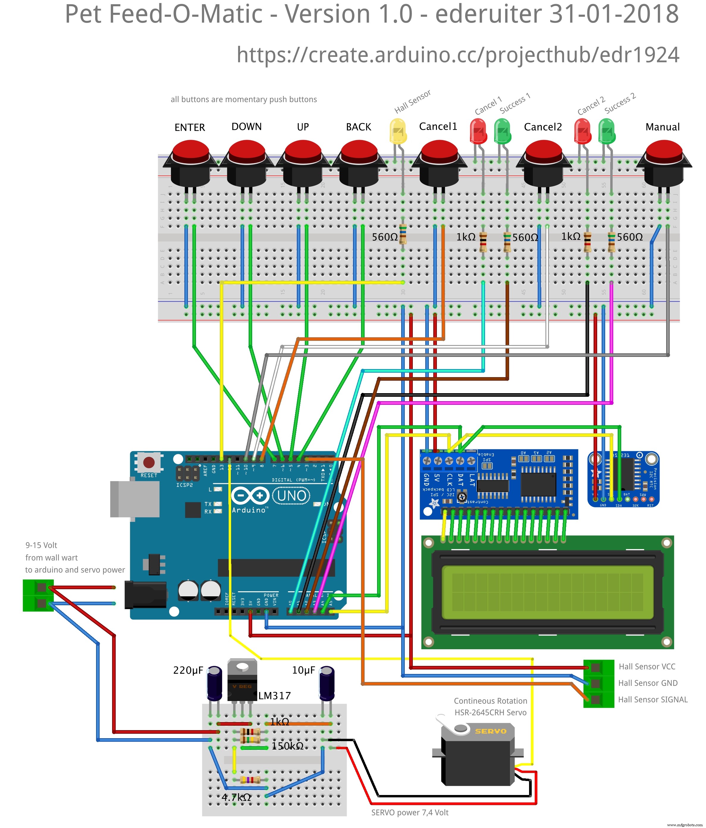 I used Arduino IDE 1.8.2. BE CAREFUL NOT TO HAVE TWO VERSIONS OF THE SAME LIBRARIES IN YOUR LIBRARIES FOLDER!!arduino_pet_feeder_final_eng_v1_0-ino_hex_libraries_dsoo0HscCr.zip
Manufacturing process
- Arduino Nano Bundle: CrazyCircuits, DFRobot Sensors & Tools – Build Projects with Confidence
- Build Your Own Arduino Tamagotchi: A Digital Pet DIY Project
- Control Two Stepper Motors with Arduino Nano & Joystick – Simple Tutorial
- Arduino‑Based Remote‑Controlled Pet Feeder: DIY Kit & Build Guide
- Build a Handheld Geiger Counter Using Arduino Nano
- High-Performance 2.8” TFT Shield for Arduino Nano – 320×240 SPI Display
- Smart 3D Printed Pet Feeder Powered by Arduino Nano
- Arduino Nano Analog Clock with DS3231 RTC & 1mA Ammeter – Precision Wooden Timer
- Smart IoT Pet Feeder: Automated Feeding System with Motion Detection
- Master the Arduino Nano: A Step‑by‑Step 6‑Part Tutorial