


Extend Arduino PWM with TLC5940: A Complete 16‑Channel LED Driver Guide
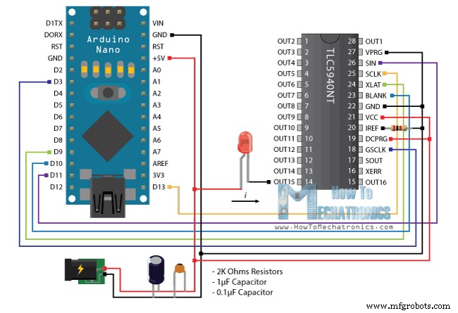
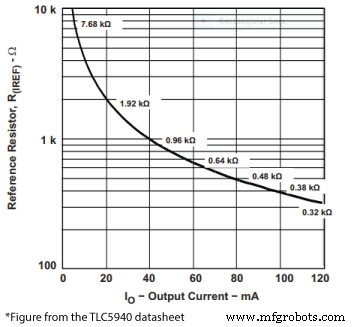
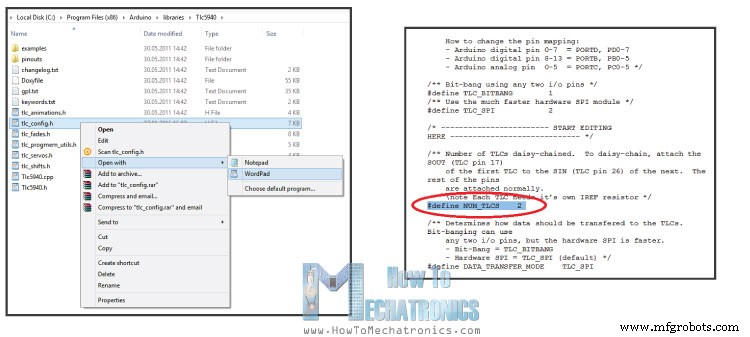
In this Arduino Tutorial we will learn how to use the TLC5940 PWM Driver using the Arduino Board. The TLC5940 is a 16-Channel LED Driver which provides PWM outputs and it’s perfect for extending the Arduino PWM capabilities. Not just LEDs, but with this IC we can also control servos, DC Motors and other electronics components using PWM signals. Daisy chaining is a great feature which means that we can connect multiple TLC5970 ICs together in series. With this we can extend the Arduino’s PWM capabilities to more than 16 outputs, for example 32, 48, or 64 PWM outputs and still use the same 4 pins used by the Arduino Board as for controlling one TLC5940 IC. You can get the components for this tutorial from any of the sites below: For controlling the TLC5940 we need to occupy 4 pins of your Arduino Board. As we will use the TLC5940 Arduino Library made by Alex Leone we need to connect the IC to the Arduino according to his library configuration or using the following circuit schematics: The circuit schematics above is using external power supply for powering the LEDs, but also it can be connected just using the Arduino VCC itself if the total amount of drawn current doesn’t exceed the limit of the Arduino (Absolute Maximum Rating, DC Current VCC and GND Pins – 200 mA). We also need to note that the TLC5940 is a constant-current sink, so the current flow towards the output pins. This means that when connecting LEDs we need to connect the negative lead (Cathode) to the output pin of the IC and the positive lead (Anode) to the 5V VCC. We also need 2 capacitors for decoupling and a resistor for controlling the amount of current that flow through the outputs. The value of the resistor depends on the component that we want to control and it can be selected using the following diagram from the datasheet of the TLC5940. So according to the diagram, for controlling LEDs which require 20mA current we need a 2K resistor. Once we download and install the TLC5940 Arduino Library made by Alex Leone we can use his “BasicUse” demo example for understanding how the control the outputs of the IC. Here’s a simple code that I made for this tutorial for controlling 16 LEDs using this library. Read the comments in the code for understanding how the functions works. For connecting more then one of these ICs in series we can use the same circuit schematics as shown above. The only difference is that the SOUT (Signal Output – pin 17) of the the first IC needs to be connected to the SIN (Signal Input – pin 26) of the second IC and so on. As for the programming part we need to make some modifications. In the TLC5940 library folder we need to modify the tlc_config.h file and change the value of the variable NUM_TLCS to the number of TLC5940 ICs connected in series and in our case that value is 2. With this done, now we can easily address all the LEDs from 0 to 31 and use the same method of programming as previously described. As an example, on the following link, you can check out my DIY LED Heart Photo Frame – Arduino Project where I use 2 TLC5940 ICs for controling 32 LEDs.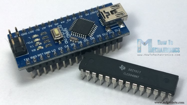
Basic Features
– 0 mA to 120 mA (VCC > 3.6V)
– 0 mA to 60 mA (VCC < 3.6V)Arduino and TLC5940 Wiring
Source Code
/*
 * Arduino and TLC5940 Tutorial - Simple Example
 * by Dejan Nedelkovski, www.HowToMechatronics.com
 */

#include "Tlc5940.h"

void setup() {
  Tlc.init(0); // Initiates the TLC5940 and set all channels off
}

void loop() {
  Tlc.set(0,4095); //(Output Pin from 0 to 15,PWM Value from 0 to 4095)
  // Note: The previous function doesn't activates the output right away. The output will be activated when the Tlc.update() function will be executed!

  Tlc.update(); // Activates the previously set outputs
  delay(1000);

  // For activating all 16 outputs at the same time we can use a for loop for setting all of them to be set to PWM value of 4095. Then  the Tlc.updata() function will active them all at the same time.
  for (int i = 0; i < 16; i++) {
    Tlc.set(i, 4095);
  }
  Tlc.update();
  delay(1000);

  //The Tlc.clear() function clears all the outputs, or sets the PWM value of all outputs to 0
  Tlc.clear();
  Tlc.update();
  delay(1000);

  // This for loop will active all 16 LEDs one by one
  for (int i = 0; i < 16; i++) {
    Tlc.set(i, 4095);
    Tlc.update();
    delay(200);
    Tlc.clear();
    Tlc.update();
    delay(200);
  }
}Code language: Arduino (arduino)
Controlling more then one TLC5940

Manufacturing process
- Create a Secure Arduino RFID Lock – Step‑by‑Step Guide
- Build a Universal IR Remote with Arduino: Step‑by‑Step Guide
- Arduino Nano Fingerprint Sensor Project – Step‑by‑Step Tutorial
- Build JARVIS v1 Home Automation with Arduino Nano – Step‑by‑Step Tutorial
- Master Arduino Multithreading with Protothreading: A Step‑by‑Step Tutorial
- Mastering I2C Communication with Arduino: A Practical Tutorial
- Mastering RGB LEDs with Arduino: A Step-by-Step Tutorial
- Master Arduino & MATLAB Integration: Step‑by‑Step Serial Communication Tutorial
- Arduino Tutorial 06: Connecting Arduino to Processing via Serial Communication
- Arduino Tutorial 02: Buttons & PWM – Master Digital I/O & LED Control