


Mastering Xilinx Vivado: Integrated Logic Analyzer (ILA) & Virtual Input/Output (VIO) Debugging
This tutorial walks you through using Xilinx Vivado’s Integrated Logic Analyzer (ILA) and Virtual Input/Output (VIO) cores to debug and monitor VHDL designs on‑chip. By the end you’ll know how to insert probes, configure triggers, and capture precise signal behavior without external equipment.
Overview
Throughout the article we’ll reference Vivado screenshots. Click each image to enlarge. Use the sidebar or the mobile pop‑up navigation for quick access.
ILA and VIO
The ILA IP lets you probe internal FPGA signals in real time, while the VIO IP allows you to drive internal signals from Vivado. Both are free, highly configurable, and integrate seamlessly into the Vivado workflow.
- Xilinx IP: Integrated Logic Analyzer (ILA)
- Xilinx IP: Virtual Input/Output (VIO)
Requirements
- A Xilinx FPGA board
- The Vivado Design Suite (2020.2 or newer)
- Basic VHDL knowledge
We’ll use the Kintex‑7 KC705 Evaluation Kit in the examples, but the steps apply to any modern Xilinx FPGA.
Download the Example Project
Download the ZIP containing the example design and VHDL files. Open ila_tutorial.xpr in Vivado to explore the design, or read on to create it from scratch.
Create a Project with Vivado
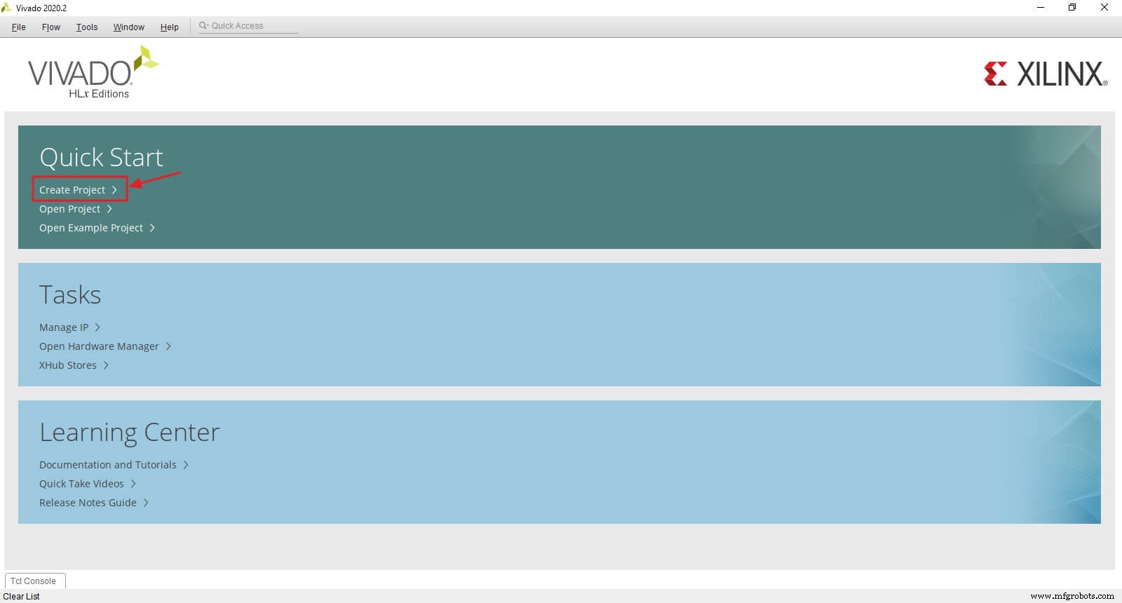
Launch Vivado and click Create Project on the welcome screen.
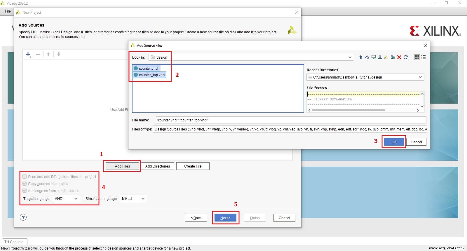
Proceed through the wizard: name the project ila_tutorial (no spaces), select RTL Project, and add sources counter.vhdl and counter_top.vhdl. Enable Copy sources into project and continue.
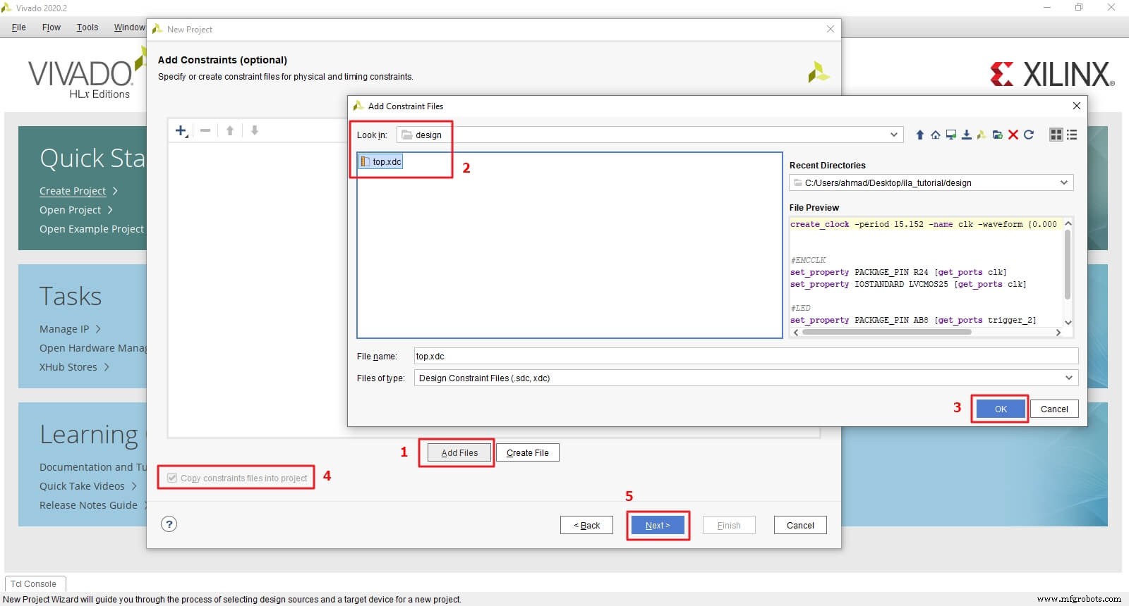
Add the constraint file top.xdc, copying it into the project. Adjust clock and LED pins to match your board, and set the correct clock period.
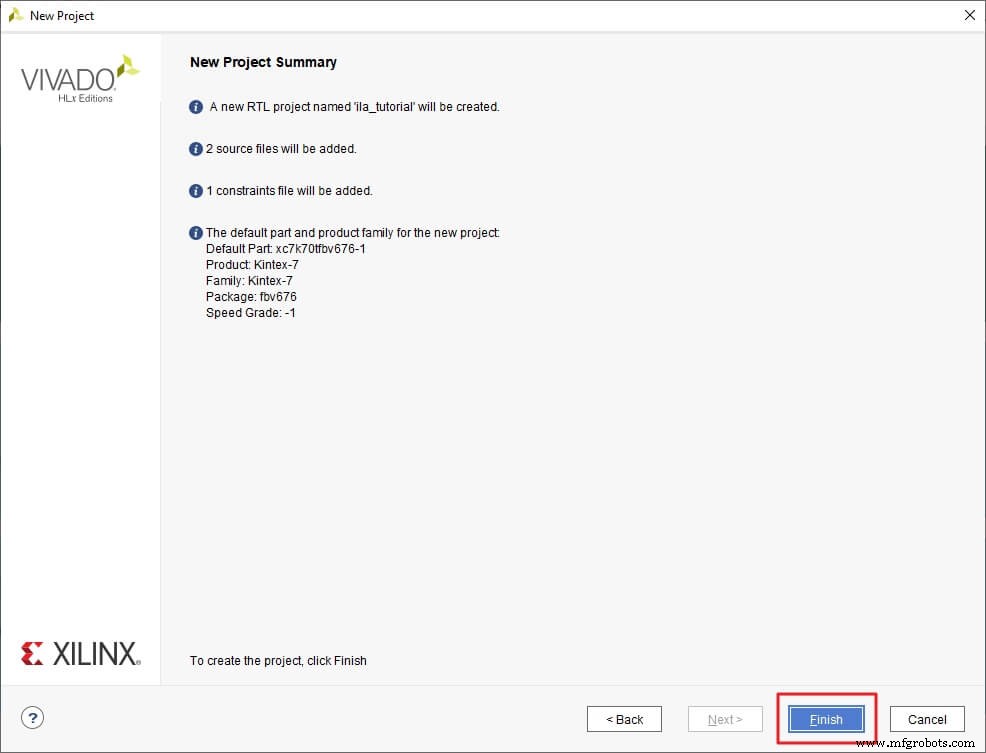
Select your board from the list and click Finish to open the project.
Design Example Overview
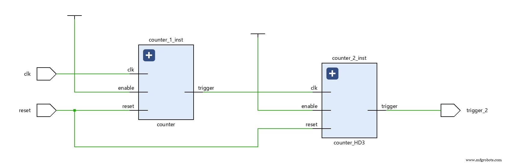
The example consists of two 4‑bit counters chained together. counter.vhdl implements a counter that increments when enabled and asserts a 1‑bit trigger output between counts 12 and 15.
Entity declaration:
----------------------------------------------------------------------------
-- ENTITY DECLARATION.
----------------------------------------------------------------------------
  ENTITY counter IS
    PORT(clk     : IN  STD_LOGIC;  -- Main clock
         reset   : IN  STD_LOGIC;  -- reset, active_high
         enable  : IN  STD_LOGIC;  -- enable the next counter
         trigger : OUT STD_LOGIC   -- trigger the next counter
        );
  END ENTITY;
Internal signals:
count– the 4‑bit counter value.trigger_o– intermediate signal connected to thetriggeroutput.
Attribute usage (will be explained later):
  ATTRIBUTE MARK_DEBUG : STRING;
  ATTRIBUTE MARK_DEBUG OF count : SIGNAL IS "true";
Sequential logic:
seq_proc: PROCESS (reset, clk)
BEGIN -- for seq_proc
  IF (reset = '1') THEN
    count     <= (OTHERS => '0');
    trigger_o <= '0';
  ELSIF rising_edge(clk) THEN
    IF (enable = '1') THEN
      count <= count + 1;
      IF (count > x"B" AND count <= x"F") THEN
        trigger_o <= '1';
      ELSE
        trigger_o <= '0';
      END IF;
    END IF;
  END IF;
END PROCESS;
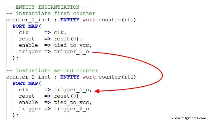
counter_top.vhdl instantiates two counters. counter_1_inst is always enabled and clocks counter_2_inst via its trigger output. Consequently, counter_2_inst increments only four times per 16‑cycle cycle of counter_1_inst.
Create a VIO Core for RESET
We’ll generate a VIO that drives the design’s reset input, enabling manual toggling from Vivado.
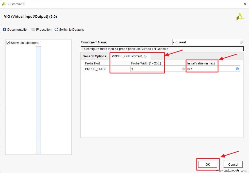
Open IP Catalog, search for VIO, double‑click VIO (Virtual Input/Output), and rename it to vio_reset. Set Input Probe Count to 0 and Output Probe Count to 1.
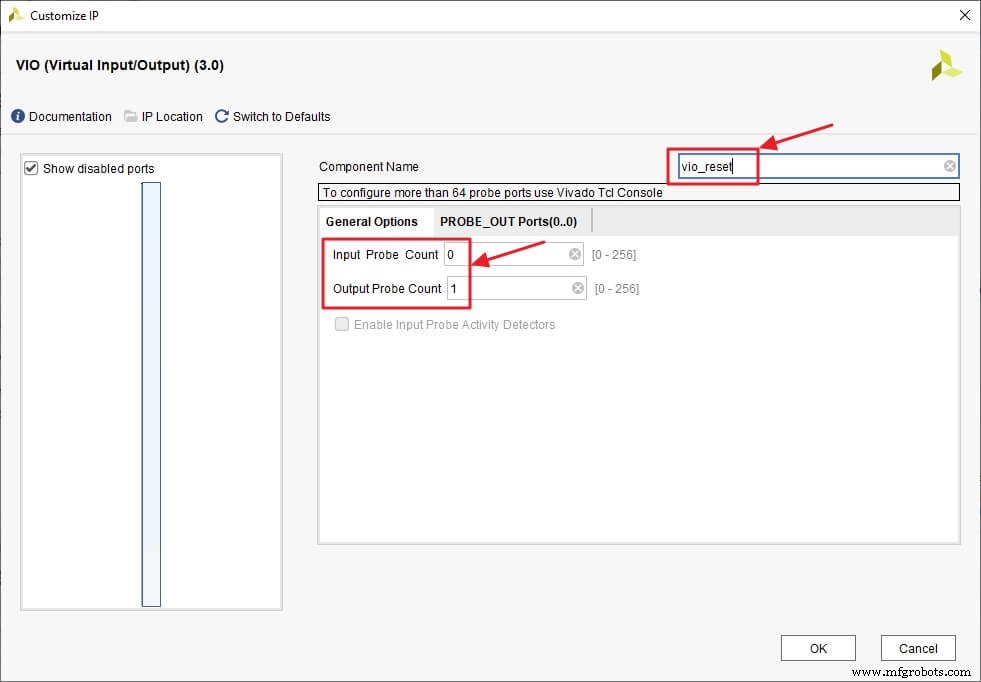
Configure the output probe: width = 1, initial value = 0x1, then click OK and Generate.
After synthesis, declare a component in counter_top.vhdl and instantiate it. Don’t forget to set flatten_hierarchy to None before re‑synthesizing.
  COMPONENT vio_reset
    PORT(
      clk        : IN STD_LOGIC;
      probe_out0 : OUT STD_LOGIC_VECTOR(0 DOWNTO 0)
    );
  END COMPONENT;
Insert Debugging Probes
Signals can be probed via three methods:
- From the VHDL source (via
MARK_DEBUGattributes). - From the Netlist or Schematic (right‑click Mark Debug).
- From an XDC/TCL file (not covered here).
VHDL Source Insertion
Declare the MARK_DEBUG attribute once per file, then apply it to the desired signals:
  ATTRIBUTE MARK_DEBUG : STRING;
  ATTRIBUTE MARK_DEBUG OF count : SIGNAL IS "true";
In the synthesized design, count will appear under Unassigned Debug Nets with a bug icon.
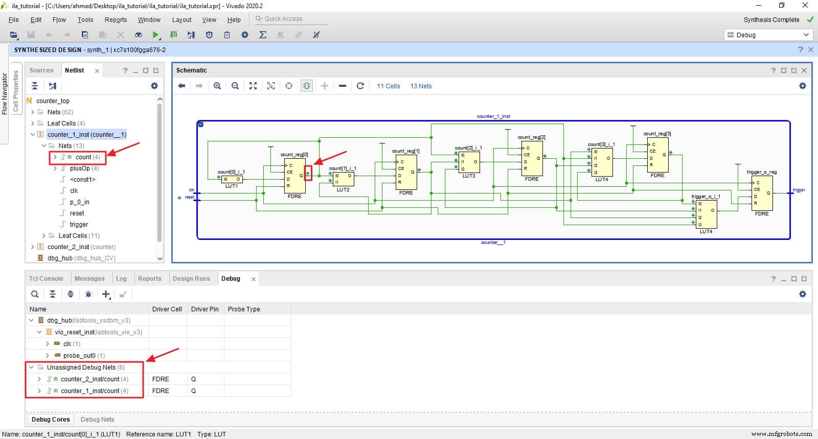
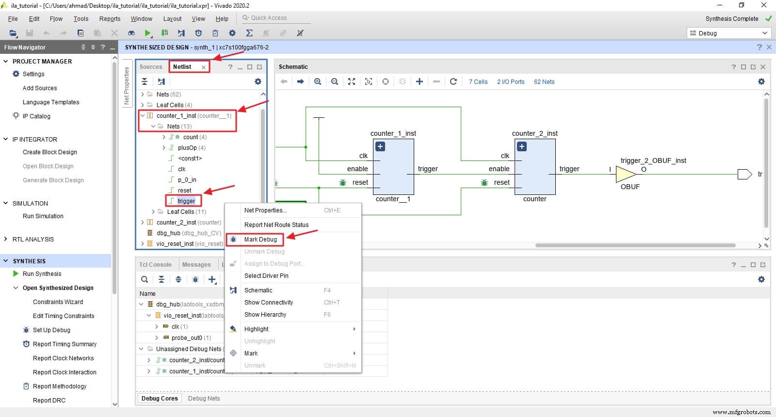
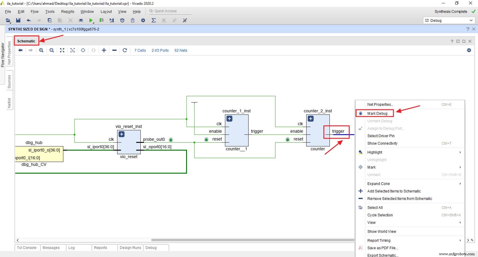
Netlist Insertion
Navigate to Netlist or Schematic, locate the trigger net, right‑click, and choose Mark Debug for both counters.
Create the ILA Debug Core
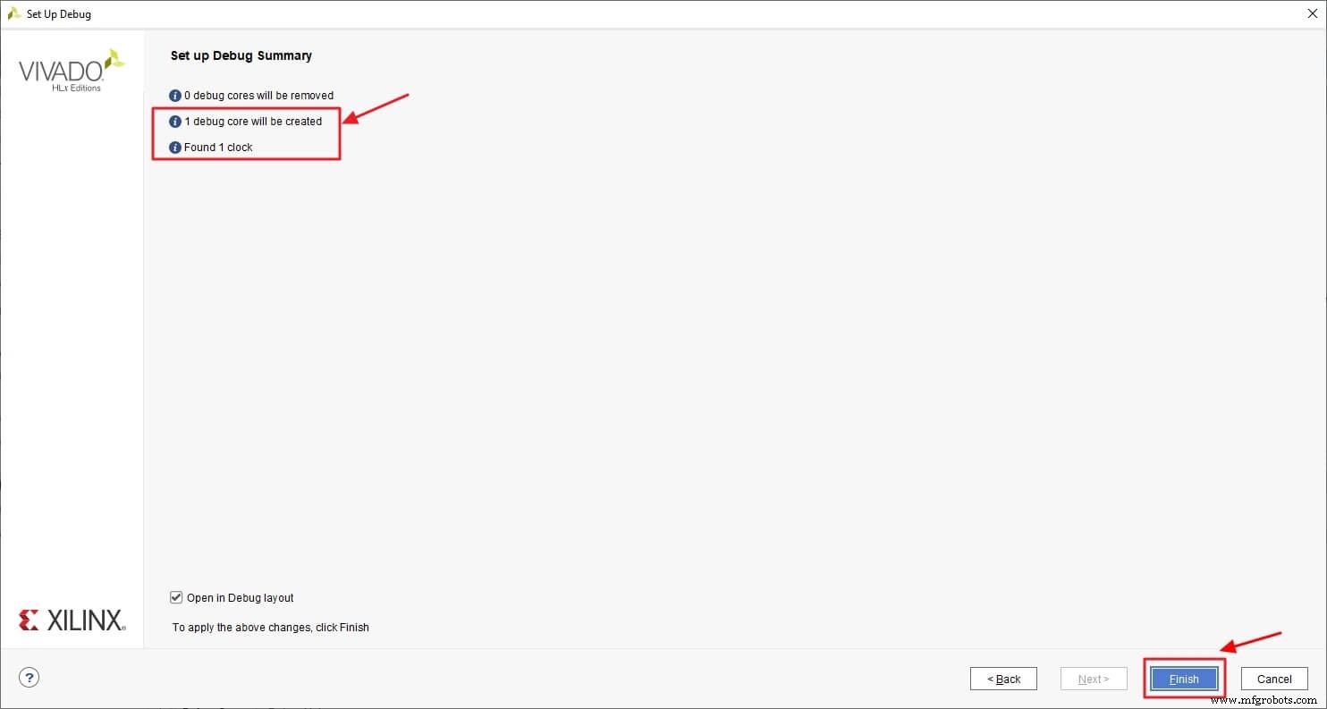
Open Set Up Debug from the IP Catalog. Vivado will list all debug nets and their clock domains. Keep all four signals for this tutorial.
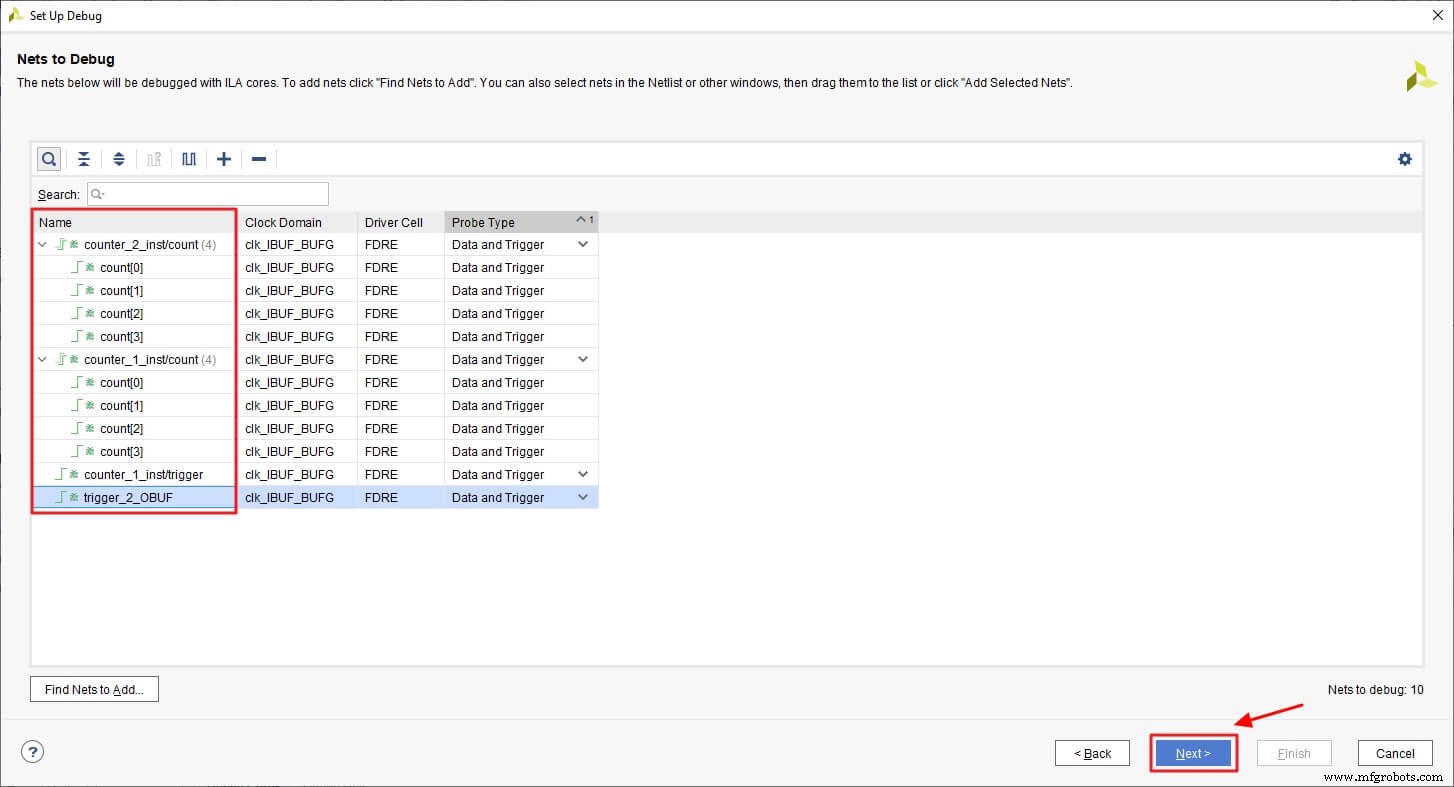
Configure the ILA FIFO depth (1024 is sufficient) and enable Capture control. Finish the wizard; Vivado generates an ILA core and a constraint file.
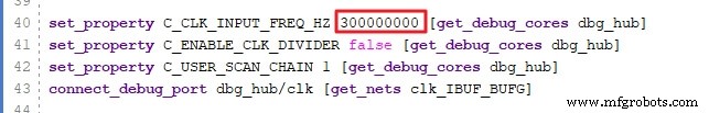
Save the constraint as ila_core.xdc. This file applies the debug attributes, creates the ILA core, configures each probe, and instantiates a dbg_hub that connects the core to Vivado. Update the hub’s clock frequency to match your design.
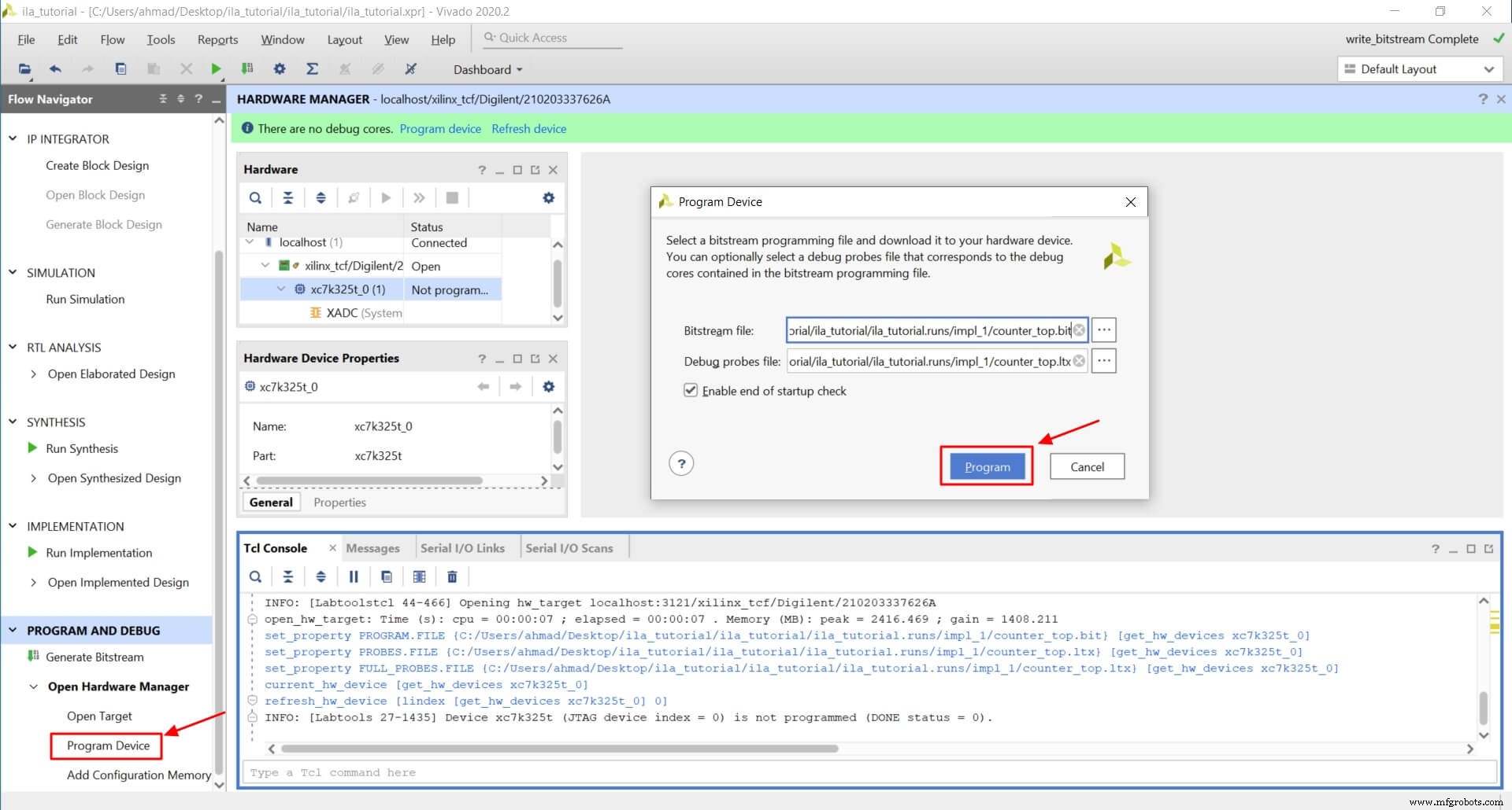
Rerun synthesis, then implementation, and generate the bitstream. Open the Hardware Manager, auto‑connect, and program the device along with the .ltx probe file.
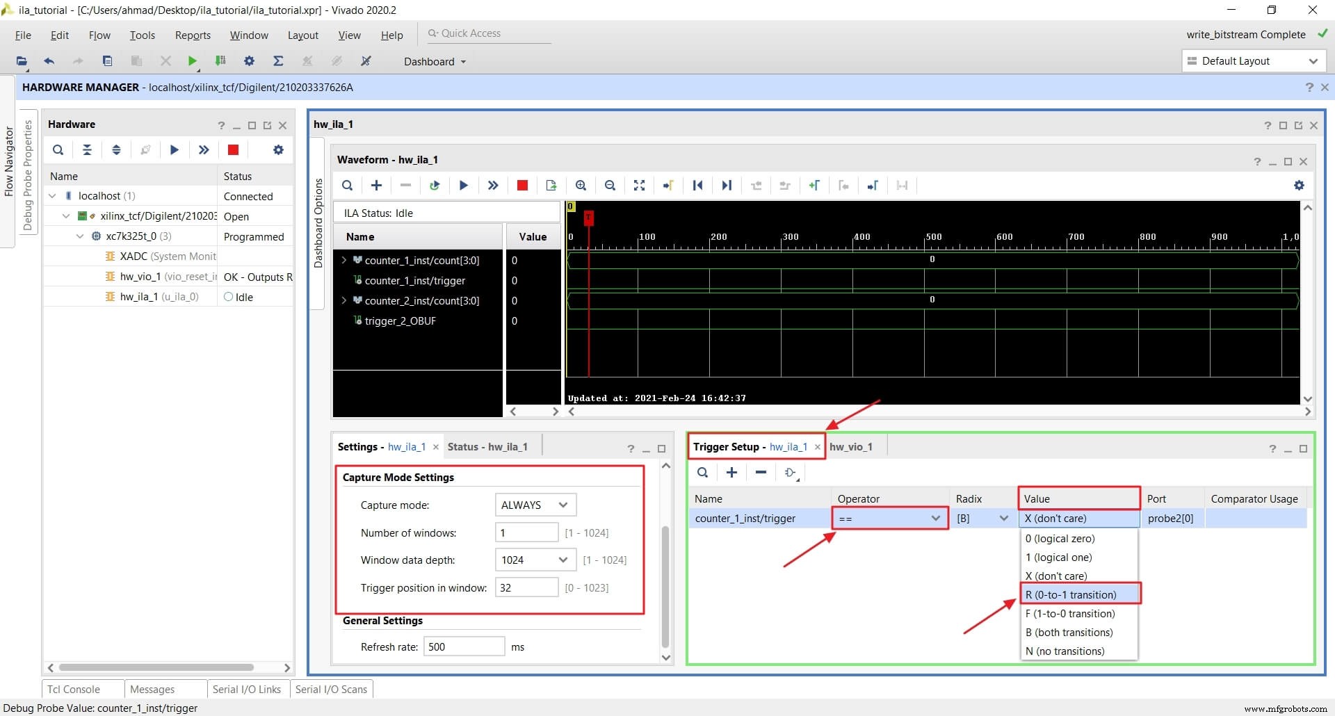
Configure ILA Triggers
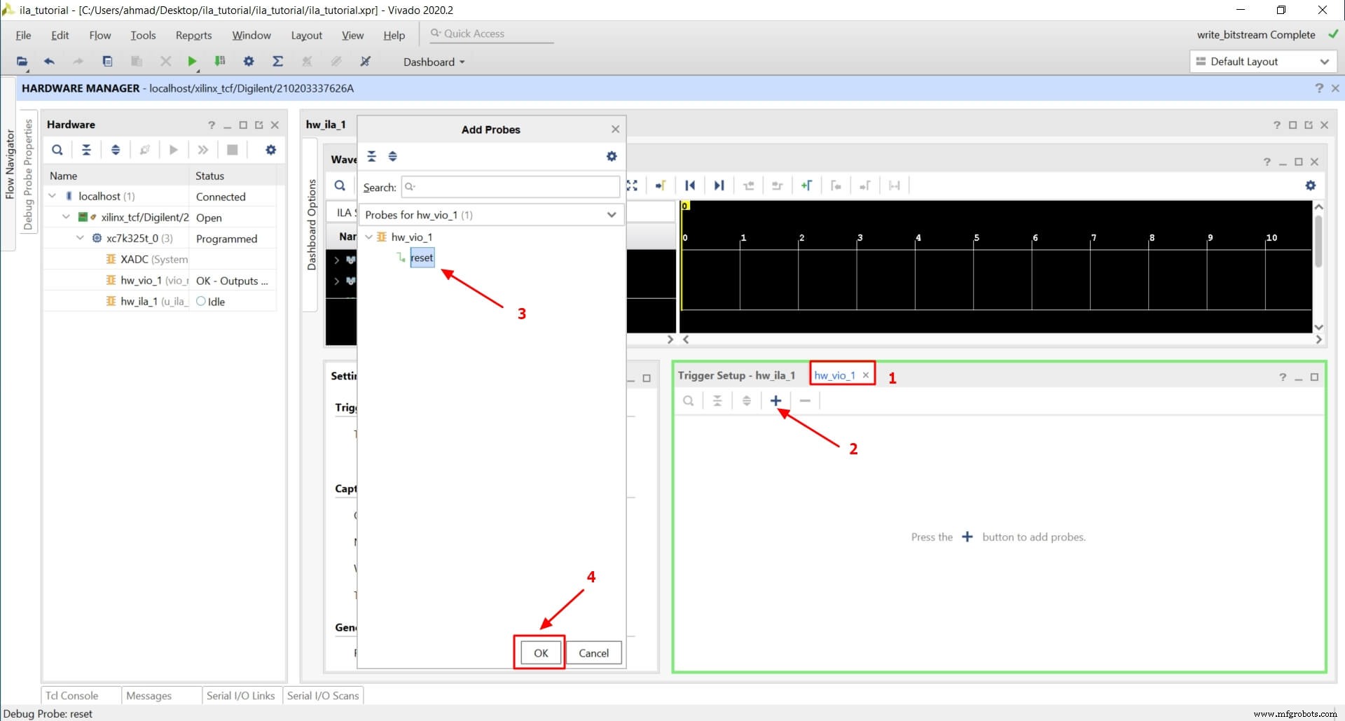
After programming, the ILA dashboard appears. Enable the VIO tab and remove unnecessary windows. Add the reset probe to the VIO so you can toggle it during capture.
Set up a trigger on counter_1_inst/trigger with a rising‑edge condition and a pre‑trigger window of 32 samples.
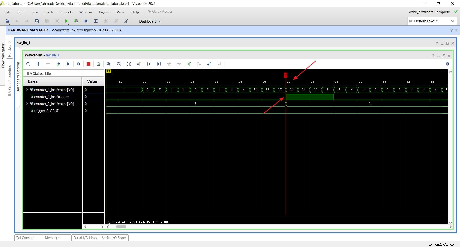
Running ILA with One Trigger
Arm the trigger (status switches to waiting for trigger) and toggle reset to 0. Once the trigger fires, the ILA records 32 samples before the event and continues until the FIFO is full.
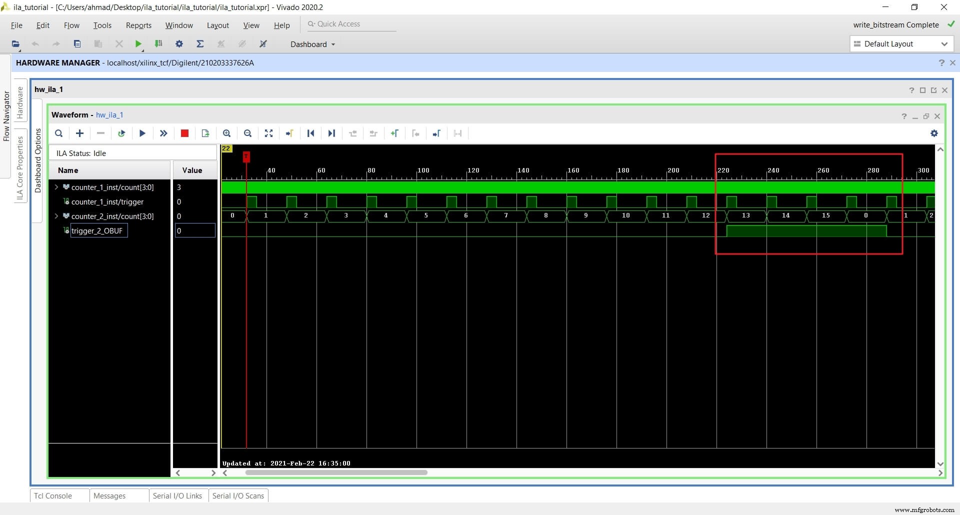
Zooming out reveals the behavior of counter_2_inst as well.
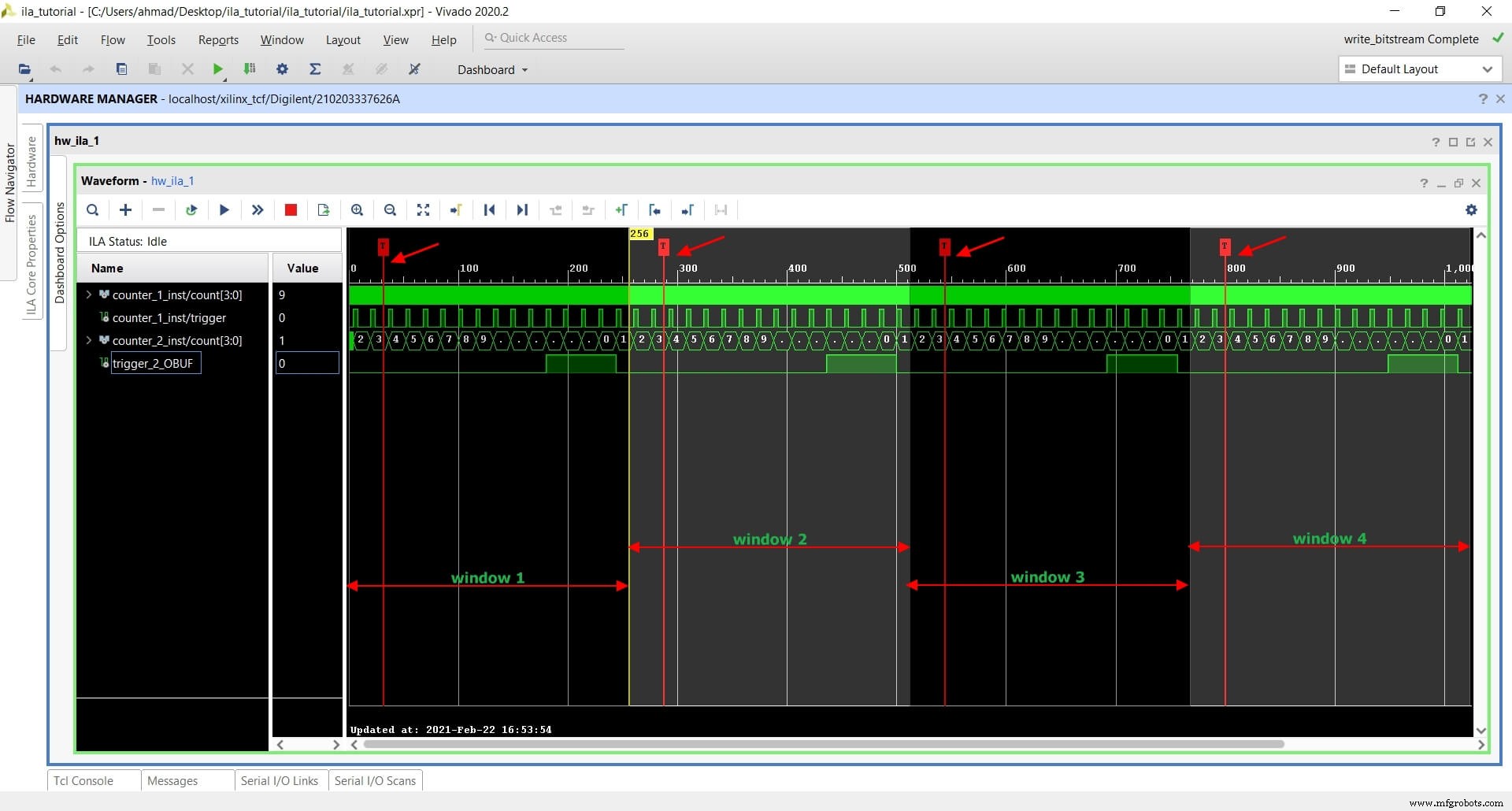
Running ILA with Multiple Triggers
For complex scenarios, chain multiple triggers. For example, trigger when counter_1_inst/count == 9 and counter_2_inst/count > 2, splitting the FIFO into four windows.
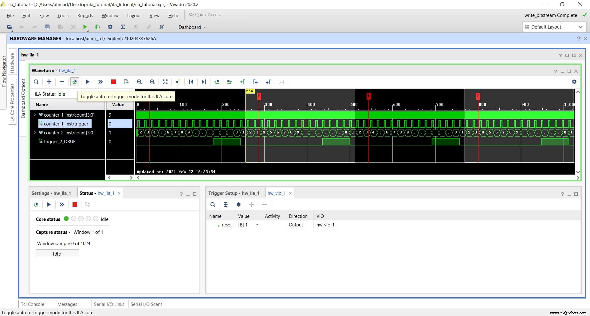
Auto Re‑Trigger Mode
Enable Auto re‑trigger to capture events that happen sporadically or at high frequency. Configure a single trigger, set FIFO depth, and arm the core.
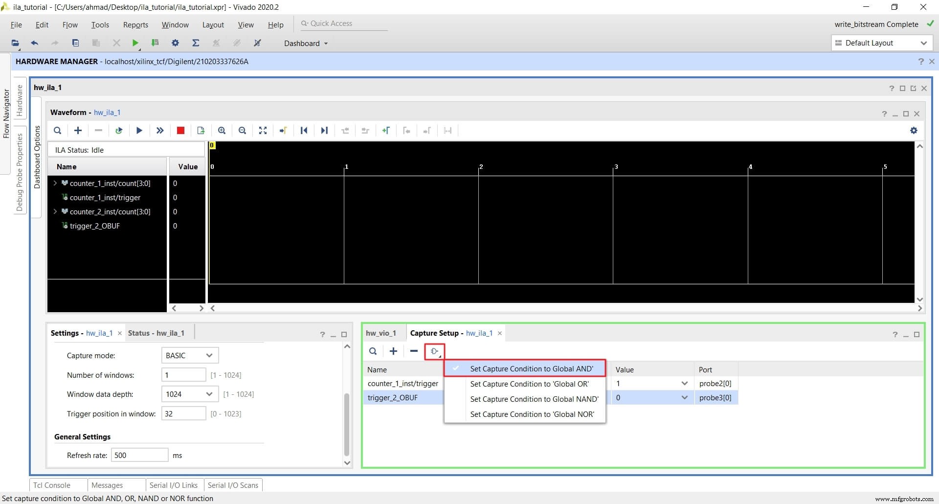
Capture Mode
Capture mode records only samples that satisfy a global condition. For instance, capture when counter_1_inst/trigger == 1 AND counter_2_inst/trigger == 0 simultaneously.
Conclusion
ILA and VIO are powerful, cost‑free tools for on‑chip debugging. By leveraging probes, multiple triggers, and capture modes, you can precisely monitor and control complex FPGA designs directly from Vivado.
VHDL
- Input & Output Coupling Techniques for Amplifiers: Capacitive, Direct, and Transformer Methods
- C# Fundamentals: Input and Output Essentials
- Mastering Python I/O and Module Imports: A Practical Guide
- Master Java Input & Output: Print, Read, and Format Your Data
- Mastering D Latches: Design, Operation, and Key Differences
- Mastering Input and Output in C Programming
- Gesture‑Controlled PC with Arduino and Python – Hands‑Free Operation
- RightHand Robotics & Element Logic Unveil Integrated Robotic Piece‑Picking System
- Digital Integrated Circuits: Types & Applications
- 10 RoboDK & Raspberry Pi Projects for Innovative Robotics