


Sealing Out Bearing Contamination: Expert Guide to Timken Bearing Seal Installation & Inspection
Bearing seals are indispensable when paired with grease lubrication. They keep grease free of contaminants, preventing accelerated wear and extending bearing life.
While most seals block debris from entering, some are engineered to allow a controlled grease ‘weep’. This weeping action carries contaminants out, lubricates the seal, and adds an extra barrier against ingress.
Equipment Inspection and Preparation
Before installing any Timken lip seal, perform a comprehensive inspection to meet the following specifications:
- Shaft surface finish (Ra): Except for PS‑1 (Model 61), require 0.25–0.50 µm (10–20 µin). PS‑1 needs 0.10–0.20 µm (4–8 µin). Finish direction must be perpendicular to the shaft axis.
- Housing bore surface finish (Ra): 2.54 µm (100 µin), with finish direction perpendicular to rotation. Provide edge relief (chamfer) and clear of defects such as burrs, scratches, or corrosion.
- Shaft hardness (Rockwell C): 30–40 C for all seals, except PS‑1 which requires 50–70 C.
- Defect clearance: Remove spiral machining marks, nicks, and any surface imperfections. Ensure the new seal does not sit in a wear groove left by a previous seal.
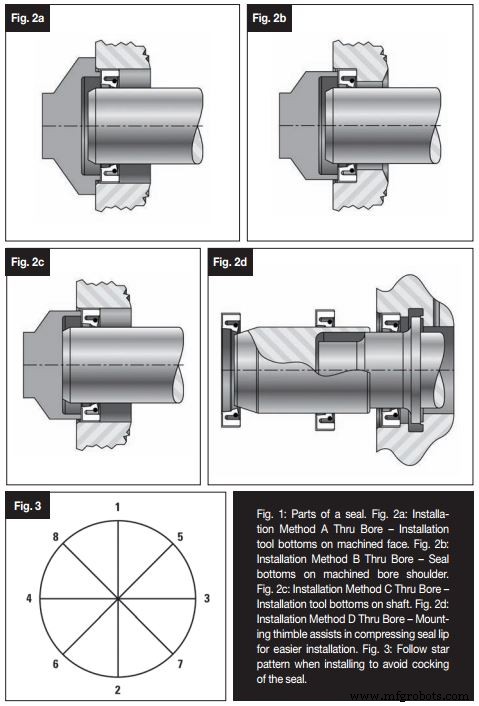
- Drive features: Keyways or splines must be covered during installation using a specialized tool (see Fig. 2) or, if size prohibits, polyethylene tape, brass shim stock, or a smooth‑edged wooden plug.
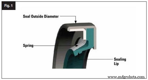
Inspect the sealing lip for cuts, indentations, or nicks. Confirm the spring (finger or garter) remains bonded or assembled. Check the seal O.D. for any damage.
Installation Methods
Solid Seal Installation
Follow the proper techniques shown in Fig. 64. If tooling is available, its diameter should not exceed 0.254 mm (0.010 in.) below the bore diameter. If tooling is not feasible:
- Place a wooden block on the seal and use a mallet to drive it gently—avoid striking the seal directly.
- Adopt a star pattern (Fig. 3) to prevent seal cocking. Position the block’s ends at points 1 and 2, hit the center, then rotate through points 3–8, striking the center each time.
- Continue until the seal is fully seated; the seal surface must match the housing surface within 0.254 mm (0.010 in.).
Split Seal Installation
Applicable to ambient‑pressure, non‑flooded environments.
- Lubricate the seal lip and shaft lightly.
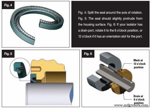
- Split the seal along the shaft axis (Fig. 4) and place it around the shaft.
- Insert the seal from the split ends into the housing bore, ensuring the split ends remain together.
- Work downwards on both sides until the seal is seated; it should protrude 0.381 mm (0.015 in.) from the housing surface (Fig. 5).
- Machining depth of the housing must match the seal width specified on the packaging.
Inspection After Installation
Check for leaks around the sealing lip and O.D. Verify the seal does not sit in any previous shaft groove.
Isolator Installation
Before installing an isolator, perform the following safety and inspection steps:
- Disconnect all power and adhere to safety protocols.
- Inspect shaft and bore: shaft finish must be <1.63 µm (64 µin.) with minimal lead; bore finish 2.54 µm (125 µin.). Provide chamfer or edge relief to protect the O‑ring.
- Ensure surfaces are free of burrs, nicks, and corrosion. Remove any debris.
- Cover keyways or splines with an installation tool, polyethylene tape, brass shim stock, or a wooden plug.
- Do not disassemble unitized Timken isolators; doing so voids the warranty.
- Inspect O‑ring O.D. and I.D. for defects, and lightly grease all O‑rings with the supplied lubricant.
Installation Procedure
- Using only your hands, push the isolator evenly onto the shaft.
- If the isolator has a drain port, orient it to the 6 o’clock position; for those with an orientation slot, set it to 12 o’clock.
- Non‑metallic isolators may be installed in any direction; consult Fig. 68 or your sales representative for guidance.
- Gently tap the isolator with a mallet if necessary. Flanged isolators are fully seated when the flange is flush against the housing; flangeless isolators are seated when flush with the bore face.
Post‑Installation Checks
Inspection: After installation, inspect the sealing area for damage and spin the shaft to confirm smooth operation. Avoid flooding the isolator or blocking expulsion ports, which can damage the seal.
Removal: To remove an old isolator, reverse the installation steps. If access to the rear is limited, pry the seal from the housing incrementally, taking care not to damage the shaft or bore.
Equipment Maintenance and Repair
- How Incorrect Greasing Can Trigger Bearing Failure
- To Grease or Not to Grease: Best Practices for Electric Motor Bearing Lubrication
- Combatting Corrosion in Mounted Bearings: Innovations & Best Practices
- Sealing Solutions for Industrial Bearings
- The Three‑Barrier Solution: Enhancing Bearing Longevity in Harsh Environments
- Seal Science: Optimizing Seal Performance Through Lubricant Compatibility
- 11 Expert‑Verified Bearing Myths Debunked: How to Avoid Common Failures
- Bearing Temperature Chart: Ideal Operating Ranges & Lubrication Guidelines
- Ensuring Hydraulic Fluid Purity: Key to Performance & Longevity
- Mastering Hydraulic Fluid Cleanliness: Proven Strategies to Eliminate Contamination