


Proactive Pump Care: Detecting Issues Before They Cause Downtime
By Steve Gahbauer
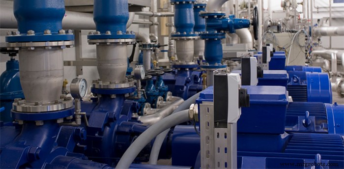
Pumps are critical to plant operations. A breakdown could halt production and result in costly downtime, repair and/or replacement. Trouble will come at the most inconvenient time, which is why it’s important to stay ahead of potential problems.
Each pump has its own sound and vibration patterns. Once “normal” is established, pay attention to day‑to‑day changes in these patterns – they could mean trouble. Increased or erratic vibration of the driver is often the first symptom of an impending breakdown. Other changes include reduced speed, decreased flow rate, excessive leakage and strange noises.
Failure causes such as unevenly worn parts, bent shafts, loose impellers and signs of corrosion or abrasion become evident when a pump is pulled and disassembled.
Michael Dufresne, customer support services at Sulzer Pumps (Canada) Inc. in Toronto, provided six troubleshooting guidelines at a recent Education Day of the Hamilton Section of the Society of Tribologists and Lubrication Engineers (STLE).
- Selection. Review ISO 13709 (API 610) for hydraulic selection criteria: the rated duty flow should be within 80–110% of best‑efficiency flow; pumps should operate within 70–120% of best‑efficiency flow; they should be capable of at least a 5% head increase at rated condition; and the head rise to a shut‑off valve should be at least 110% of rated head.
- System curves. Friction loss always exists in a system due to piping, valves, strainers and reducers. Flow increases raise friction loss, which is proportional to the square of flow. The net positive suction head (NPSH) available at a site must always exceed the pump’s required NPSH. Every liquid has a unique vapor pressure that varies with temperature, so the required NPSH can only be estimated by testing. Impellers designed for low‑NPSH applications typically have high suction‑specific speeds and can struggle at low flows. Pumps operate best within a “comfort zone” on their characteristic curves, which aligns with the API 610 preferred flow bands.
- Cavitation. Cavitation occurs when liquid pressure drops below its vapor pressure, producing noise and vibration as vapor bubbles collapse on the impeller. Suction‑specific speed is a rating that indicates a pump’s ability to operate under low‑NPSH conditions; industry standards recommend a range of 10 000–11 000.
- Backflow and vibration. Flow spikes from the impeller can impact adjacent stationary elements such as anti‑swirl ribs or flow straighteners, generating vibration at the vane‑pass frequency. The swirling liquid ring slows with distance from the inlet; when it strikes stationary parts farther away, it produces lower‑frequency vibration. Staggered discharge vanes reduce this pulsation. Common vibration causes include unbalance, shaft misalignment, oil whip and foundation failures.
- Performance modifications. Under‑filing the impeller discharge vanes enlarges the outlet area, improving performance. Over‑filing suction vanes or cutting them back reduces the required NPSH. Removing material from the pressure side of the impeller discharge vanes thins the blade to about one‑third of its original width, leaving discharge performance largely unchanged. Cutting back volute lips on low‑ and medium‑specific‑speed pumps shifts the peak efficiency and head to the right in proportion to the change in volute area.
- Lubrication. The most common oils for pump bearings are pure or refined mineral oils and synthetic oils for high temperatures. Additives enhance lubricant performance: antioxidants stabilize oxidation to reduce corrosion and viscosity rise; anti‑foaming additives prevent foaming that diminishes load‑carrying capacity; film stiffeners form a surface layer with higher tension to reduce metal‑to‑metal wear; organic zinc compounds keep the ball and races apart; active EP additives chemically bond with bearing metal to lower friction; solid additives like molybdenum disulfide further improve lubrication. The oil level should sit halfway through the bottom ball when the pump is at rest. Most pumps can cool the oil when it becomes too hot; do not attempt to cool a bearing by cooling the housing, as steel expands and contracts. Heat reduces oil velocity, creating a feedback loop that generates more heat. The interference fit conducts heat from the bearing onto the shaft. Ensure no knurled surfaces or polymers are used to build the shaft to the proper dimension.

Effective troubleshooting begins with knowing your pump. Familiarize yourself with its normal performance, monitor operation closely, and address problems promptly to avoid costly production interruptions.
Steve Gahbauer is an engineer, a Toronto‑based business writer and a regular contributing editor to PLANT. E‑mail gahbauer@rogers.com. Comments? E‑mail jterrett@plant.ca.
Equipment Maintenance and Repair
- Ohm’s Law Explained: A Water‑Pipe Analogy for Clear Intuition
- Finding a Reliable Z‑Wave Alternative: 2.4 GHz Mesh & Star Networks
- Implementing Smart Redundancy: Enhancing Reliability Without Breaking the Bank
- Invitation for North American Experts to Review Draft ANSI/HI 1.4 Standard on Rotodynamic Pumps
- Hydraulic Institute Invites Qualified Reviewers for Updated ANSI/HI 11.6 Submersible Pump Test Standard
- Pump Flow Pulsation: A Leading Cause of Pump Vibration Problems
- 6 Common Causes of Pump Vibration Issues
- How to Select the Ideal Hydraulic Pump for Your System
- HS Code for Hydraulic Pump – Classification & Usage
- Understanding Why Pumps Lose Flow & How to Prevent It