


Fanuc G15/G16 Polar Coordinate Interpolation – End & Begin Operations
G15 End Polar Coordinate Interpolation
G15 End Polar Coordinate Interpolation
Programming
G15
G16 Begin Polar Coordinate Interpolation
G16 Begin Polar Coordinate Interpolation
Programming
G16
Between G16 and G15 points can be defined by polar coordinates.
The selection of the plane in which polar coordinates can be programmed occurs with G17 – G19.
With the address of the first axis the radius will be programmed,
with the address of the second axis the angle will be programmed,
both related to the workpiece zero point.
Example
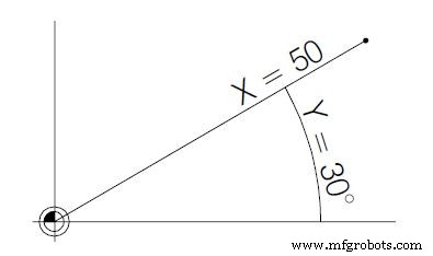
N75 G17 G16
N80 G01 X50 Z30
first axis: radius X=50
second axis: angle Y=30
Master Fanuc G17, G18, G19 Plane Selection for Precise CNC Control
Optimized Turret Unclamp with Okuma M203: NC Command Guide
CNC Machine
- Fanuc G68 Coordinate Rotation G‑Code Example for CNC Machining
- Fanuc G68 Coordinate Rotation: Precise Axis Alignment for CNC Machining
- Master Fanuc Circular Interpolation (G02/G03) with Practical Code Example
- Fanuc G68 Coordinate Rotation: Practical Subprogram Example for CNC Machining
- Comprehensive Fanuc G-Code Reference for CNC Programming
- Fanuc CNC Program Example: G52 Local Coordinate & G15/G16 Polar Coordinates
- Fanuc G15 & G16: Polar Coordinate Bolt Circle CNC Program Example
- Fanuc G07.1 Cylindrical Interpolation Program Example: Step-by-Step CNC Code
- Fanuc G07.1 Cylindrical Interpolation: A Step‑by‑Step CNC Programming Example
- NCT Programming: Circular Drilling with G81 Cycle and G16 Polar Coordinates