


USB Type‑C: The Reversible Connector That Simplifies Embedded Design
The latest USB 3.1 specification introduces the USB Type‑C connector, finally eliminating the orientation issue that plagued earlier USB standards. While not the sole drawback of legacy USB, the inability to insert cables in either direction has been a persistent nuisance for designers and users alike.
In my own experience, it often takes three attempts to successfully plug a USB cable into a device. The new Type‑C connector resolves this by offering a mechanically symmetrical design that works flawlessly in any orientation.
(Source: Duane Benson)
USB 3.1 brings significant upgrades: higher power delivery, faster data rates, and smart cables that self‑detect their role and adjust accordingly. The added complexity is managed by small embedded electronics within the cable that negotiate power levels and data modes on both ends.
Reading the full spec can feel daunting, especially when compared to the familiar USB Micro‑B and FTDI USB‑to‑UART solutions we use in embedded projects. However, the USB‑IF specification explicitly supports wiring a Type‑C connector into existing USB 2.0 designs with minimal effort and no hidden pitfalls.
My first Type‑C implementation is in an Arduino‑compatible electronic ruler I’m co‑designing with Max Maxfield of Embedded.com. The board already uses an FTDI FT231X to bridge the MCU UART to a USB Micro‑B connector; now I’ve added a Type‑C port so the device can be powered and programmed via either cable.
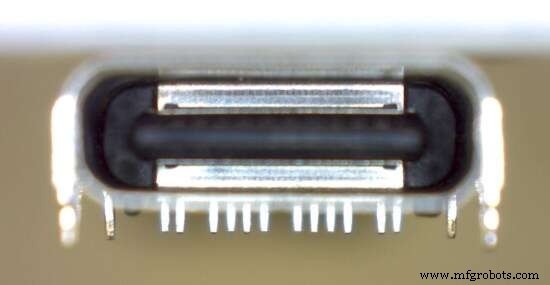
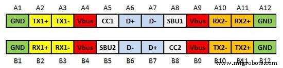
The diagram below shows the pin layout for signal, power, and ground connections from a face‑on view of the connector.
(Source: Duane Benson)
Both sides of the connector provide identical power and ground pins, as well as duplicated D+ and D– lines. For USB 2.0 compatibility, we only need to care about D+, D–, Vbus, Ground, CC1, and CC2. The remaining pins—TX1/2/+/–, RX1/2/+/–, and SBU1/2—serve higher‑speed and alternate modes such as USB 3.1, DisplayPort, and HDMI.
Only the power, ground, and USB 2.0 data lines are mirrored exactly. In higher‑speed modes, the smart cable’s electronics ensure proper routing, while the connector’s duplicate D+/D– pairs simply provide a universal, reversible interface with two fewer wires in the cable.
CC1 and CC2 act as pull‑down resistors that inform a smart cable or upstream device of cable orientation and power delivery options. A basic USB 2.0 device requires 5.1 kΩ pull‑downs (R3 and R4) on both CC1 and CC2.
(Source: Duane Benson)
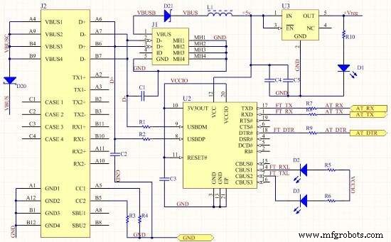
J2 is the Type‑C connector, while J1 is the Micro‑B connector. All D+ and D– pins connect to the FT231X (U2) USBDM and USBDP pins through 27 Ω resistors (R1 and R2), mirroring a standard USB 2.0 layout. All other pins remain unconnected.
To protect against back‑feeding of 5 V if both cables are inserted simultaneously, I added protection diodes (D20 and D21). While data line collision will simply render the connection unusable, the diodes safeguard the MCU from potential voltage spikes.
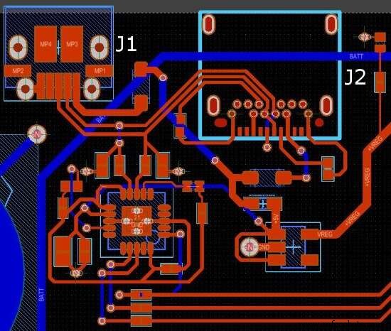
The layout below illustrates the relative sizes of the Micro‑B (J1) and the surface‑mount or through‑hole Type‑C (J2) connectors.
(Source: Duane Benson)
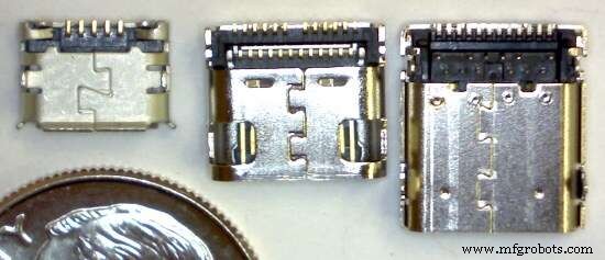
A comparative view shows a USB Micro‑B (upper left), a surface‑mount Type‑C (upper middle), and a combined SMT/through‑hole Type‑C (upper right), all measured against a US dime for scale.
(Source: Duane Benson)
Until USB Type‑C becomes the ubiquitous standard, I’ll continue to provision both connectors on my boards, provided space permits. How about you? Are you already deploying Type‑C in your embedded systems, or is there a timeline for adoption?
Embedded
- Java Hello World: Your First Program
- Herbal Extracts: Production, Types, and Health Benefits
- USB‑C: The Unified Power Connector That Cuts E‑Waste and Simplifies Life
- Mastering USB‑C: Design Challenges and Practical Solutions for High‑Speed Data and Power
- Bulgin Unveils Rugged 10Gb/s USB‑C Connector, IP69K/IP68 Rated for Harsh Environments
- AAEON Unveils BOXER‑8150AI: High‑Speed Edge AI with 8 USB 3.0 Ports and NVIDIA Jetson TX2
- USB‑C Pinout & Features: A Comprehensive Guide for Professionals
- Beginner’s Guide to Verilog: Hello World Example
- Everything You Need to Know About USB‑C: Features, Pinouts & Power Delivery
- Understanding Power Connectors: Types, Functions, and Safety Tips