


Optimizing Motor Drivers for Battery‑Powered IoT Devices
Master Motor‑Driver Design to Extend Battery Life in IoT Systems
Battery‑powered Internet‑of‑Things devices—from smart meters and sanitation sensors to video doorbells, robotic toys, personal hygiene gadgets, and electronic locks—often rely on motors, solenoids, or relays. The interplay between the battery’s chemistry, its voltage sag, and the motor’s current draw creates a unique set of design challenges: maintaining reliable operation as the battery discharges, trimming standby power to maximize runtime, and managing the high peak currents seen during startup and stall.
Below are proven strategies that help you navigate these challenges and deliver robust, long‑lasting battery‑powered motor systems.
Overview of Battery‑Powered Motor Systems
The voltage available to a motor driver depends on several factors: the battery chemistry, depth of discharge (DoD), operating temperature, load current, and the series/parallel configuration of the cells. While battery modeling can be complex, a simple open‑circuit model using VOCV (open‑circuit voltage), RBAT (internal resistance), and the measured VBAT gives designers a clear starting point. See Figure 1 for a block diagram.
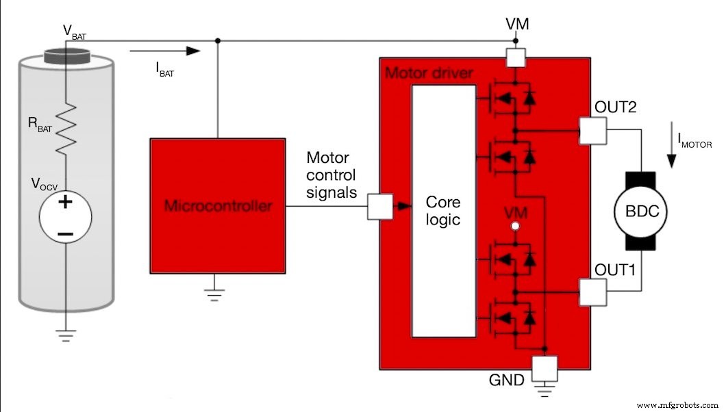
Figure 1. Block diagram of a battery‑powered system with a motor driver and motor.
The table below lists typical voltage ranges, internal resistances, and capacities for common battery chemistries. These figures are derived from manufacturer data sheets and provide a practical reference for component selection.
| Battery chemistry and stackup | VBAT (full charge) | VBAT (depleted) | RBAT | Capacity |
| 2 AA (alkaline), Duracell OP1500 |
1.7 V/cell |
0.8 V/cell |
100–250 mΩ/cell |
2,400 mAh* |
| 3 AAA (alkaline), Panasonic LR03AD |
1.55 V/cell |
0.8 V/cell |
135 mΩ/cell (avg) |
2,640 mAh |
| 4 AA (alkaline), Energizer E91 |
1.5 V/cell |
0.8 V/cell |
150–300 mΩ/cell (fresh) |
2,500 mAh* |
| 1 Li‑ion (Panasonic NCR18650BF) | 4.2 V | 2.5 V | 77 mΩ* | 3,200 mAh |
| 2 Li‑poly (Farnell SR674361P) |
4.2 V/cell |
2.75 V/cell |
160 mΩ/cell |
2,000 mAh |
*Parameters calculated from other battery data‑sheet parameters
Table 1. Approximate battery parameters for various chemistries and stackups.
As the battery discharges, VOCV falls while RBAT rises. The load current (IBAT) further drops the terminal voltage by VBAT = VOCV – IBAT·RBAT. Figure 2 illustrates how these parameters evolve over time for typical alkaline and lithium‑ion cells.
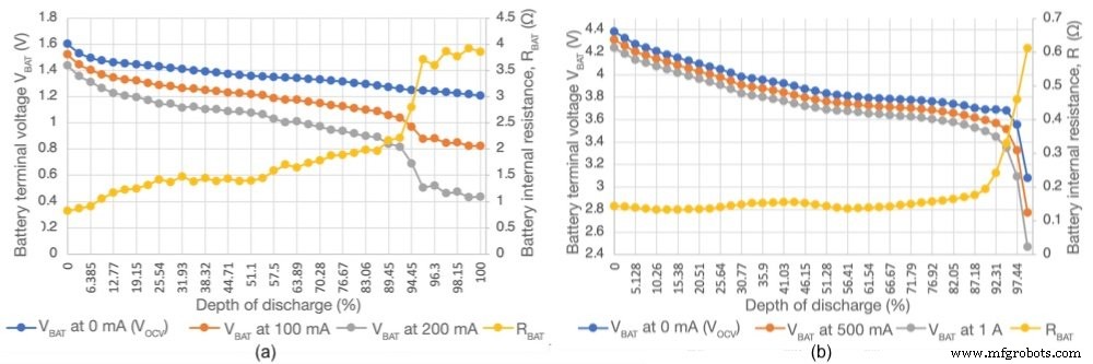
Figure 2. VBAT and RBAT curves for alkaline (a) and lithium‑ion (b) cells under varying load currents, based on TI chemical data.
Depth of discharge (DoD) expresses how far the battery has been used relative to its full capacity (mAh). A 100 % DoD means the battery is fully depleted.
Designing for a Wide VBAT Range
Because VBAT shifts with DoD and IBAT, the motor driver’s supply‑rail rating must cover the full spectrum of expected voltages. For example, a driver specified for 24‑V systems might require a minimum 4.5 V rail—an undervoltage lockout that could trip before a four‑cell alkaline pack fully discharges.
Texas Instruments’ DRV8210 and DRV8212 are designed for 1.65 V to 11 V inputs, comfortably covering a two‑cell Li‑ion stack (up to 8.4 V) and an almost‑discharged two‑cell alkaline stack (down to 1.65 V). Choosing a driver with an appropriate voltage window removes the need for additional boost converters and ensures the motor can run throughout the battery’s life.
Designing for Low‑Power Standby Mode
In most IoT deployments, the motorized component operates only a few times per day or even once per year. The system’s standby current therefore dominates overall energy consumption. Reducing standby draw is essential for long battery lifetimes.
Strategies include:
- Incorporating load switches to disconnect peripheral devices during idle periods.
- Choosing components with ultra‑low standby currents—for instance, the DRV8210/DRV8212 sleep currents are <84.5 nA.
- Eliminating resistor dividers that unnecessarily bias logic pins and using pulldown resistors set to 0 V when the device is idle.
Managing Large Currents to Reduce Energy Consumption and Increase Operating Life
High peak currents, especially during motor startup and stall, waste energy and can trigger low‑battery lockout due to the voltage drop across RBAT. Figure 3 shows typical inrush and stall current profiles.
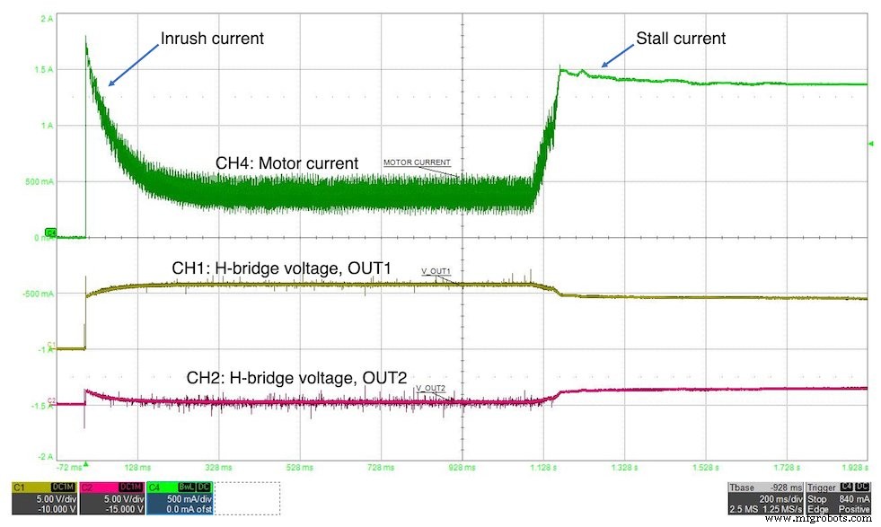
Figure 3. Inrush and stall currents.
Two techniques mitigate these peaks:
- Soft‑start. Gradually ramp the PWM duty cycle from 0 % to 100 % during motor startup, which keeps the inrush current—and the resulting voltage sag—within tolerable limits. Figure 4 contrasts hard‑start (a) and soft‑start (b) behavior on a depleted four‑AAA stack using the DRV8210.
- Stall detection. A sense resistor allows the microcontroller to monitor motor current. If the sensed voltage exceeds a threshold for a defined duration, the firmware disables the driver, preventing prolonged stall draws. Figure 5 shows a stall‑detection implementation, while Figure 6 demonstrates the current reduction achieved.
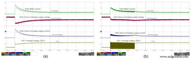
Figure 4. Hard‑start (a) vs. soft‑start (b) inrush on four depleted AAA batteries with the DRV8210.
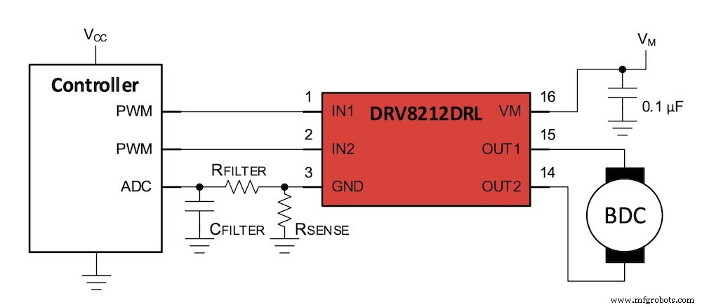
Figure 5. Stall‑detection block diagram using the DRV8212.
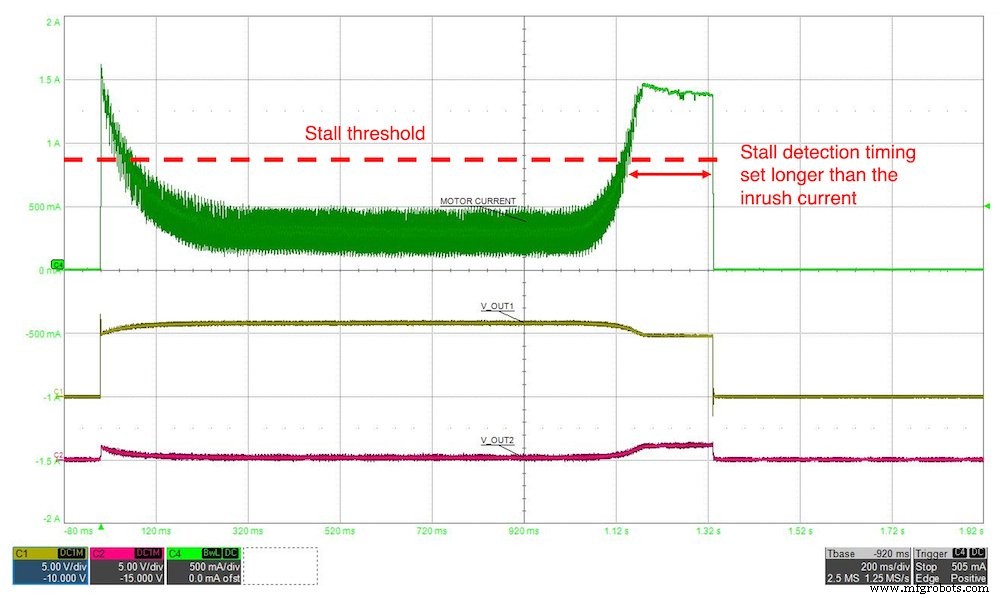
Figure 6. Motor current with stall detection vs. without.
Because battery capacity is rated in mAh, limiting both the magnitude and duration of high‑current events extends the usable lifetime of the pack.
Conclusion
Designing battery‑powered motor systems demands careful consideration of voltage variation, standby consumption, and peak currents. By selecting a driver that spans the battery’s voltage range, implementing ultra‑low‑power sleep modes, and applying soft‑start plus stall‑detection logic, designers can significantly prolong device life in applications such as smart sanitation units, motorized blinds, electronic locks, and beyond.
Industry Articles are a form of content that allows industry partners to share useful news, messages, and technology with All About Circuits readers in a way editorial content is not well suited to. All Industry Articles are subject to strict editorial guidelines with the intention of offering readers useful news, technical expertise, or stories. The viewpoints and opinions expressed in Industry Articles are those of the partner and not necessarily those of All About Circuits or its writers.
Internet of Things Technology
- Building an IoT‑Enabled Car‑Sharing Business Model in Two Days: Lessons from a Bosch Hackathon
- How Industrial IoT Sensors Drive Modern Factory Efficiency
- Battery‑Powered Stepper Motors for IoT: Reliable, Precise Actuation
- The Core of EVs: A Comprehensive Guide to Battery Systems
- Strong Leadership Drives IoT Adoption
- 5 Key Drivers of IoT Adoption in Retail Stores
- 6 Key Drivers Fueling Rapid IoT Adoption in Healthcare
- IoT Security Demystified: Protecting Your Connected Devices
- Motor vs. Actuator: How to Pick the Best for Industrial Systems
- OTTO Motors: Powering Industry 4.0 with Autonomous Material Handling