


Capacitive Accelerometers Explained: From Mass‑Spring Mechanics to Signal Conditioning
Capacitive Sensing for Accurate Acceleration Measurement
Accelerometers are the unsung heroes behind many modern technologies. In automotive safety, they trigger airbags; in photography, they keep images sharp; in data storage, they detect shock and pause operation. Micro‑fabrication has made these devices small and inexpensive, enabling their integration into everything from smartphones to industrial machinery.
In this article we dissect the physics that turns motion into a measurable voltage: a mass‑spring‑damper system converts acceleration to displacement, and capacitive sensing translates that displacement into an electrical signal. We also cover the signal‑conditioning technique that ensures the output is both linear and noise‑robust.
Measuring Acceleration with a Mass‑Spring‑Damper
A classic mass‑spring‑damper structure (Figure 1) is the heart of most accelerometers. The proof mass, attached to the sensor frame via a compliant spring, responds to external forces.
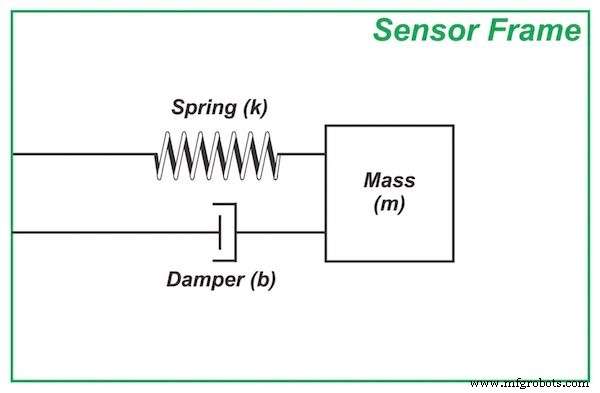
Figure 1. Mass‑spring‑damper structure
When the frame accelerates, inertia keeps the proof mass momentarily at rest. Relative to the moving frame, the mass appears displaced (Figure 2). The spring compresses or stretches, exerting a restoring force proportional to the displacement, which in turn drives the mass toward the new equilibrium. Once the transient dies out, the displacement is directly proportional to the applied acceleration.
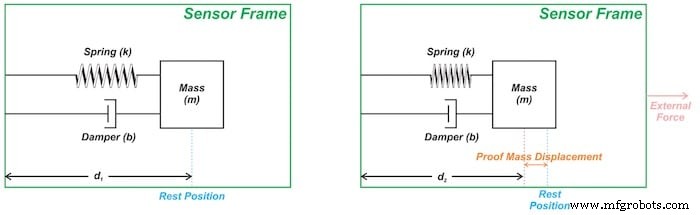
Figure 2. (a) Resting position; (b) Displacement during frame acceleration.
Key design parameters—mass, spring constant, and damping—are tuned so that the linear region of the mass‑spring relationship matches the desired acceleration range.
Converting Displacement to a Signal: Capacitive Sensing
Capacitive sensing is the most common transduction method for micromachined accelerometers. Two fixed electrodes flank a movable electrode attached to the proof mass, forming a differential capacitor pair (Figure 3).
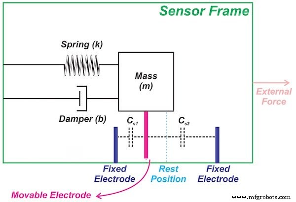
Figure 3. Differential capacitive sensing structure
As the proof mass moves, one capacitor’s plate spacing shrinks while the other expands, creating a differential change that is directly proportional to the displacement.
Signal Conditioning with Synchronous Demodulation
To read the tiny capacitance variations, accelerometers use a square‑wave excitation at ~1 MHz (Figure 4). The two fixed electrodes receive identical‑amplitude signals that are 180° out of phase. The resulting differential voltage at the bridge is zero when the mass is centered and becomes a square wave whose amplitude and phase encode displacement magnitude and direction.
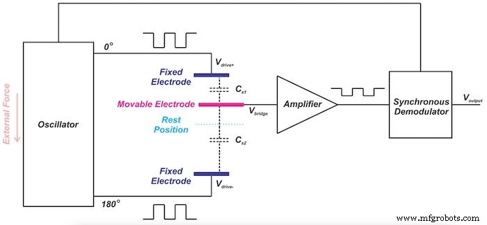
Figure 4. Simplified signal conditioning (adapted from Analog Devices’ ADXL family)
The synchronous demodulator multiplies the bridge output by the excitation waveform, converting the high‑frequency square wave into a low‑frequency DC voltage that can be amplified and digitized. This technique preserves signal integrity while rejecting common‑mode noise.
Why Differential Sensing Beats Single‑Ended Sensing
A single‑ended capacitor (Figure 5) would provide a nonlinear output because the capacitance changes are inversely related to the plate separation. This nonlinearity complicates calibration and degrades precision.
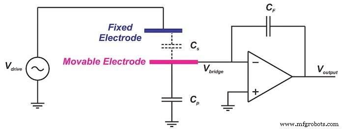
Figure 5. Single‑ended capacitive model
In contrast, the differential architecture yields a linear voltage proportional to displacement:
Equation 3 V_bridge = (Δd/d₀) · V_drive⁺
Linear behavior simplifies calibration, improves measurement repeatability, and allows the sensor to operate over a wide dynamic range.
Conclusion
We have seen how a mass‑spring‑damper system transforms acceleration into measurable displacement, and how differential capacitive sensing combined with synchronous demodulation produces a clean, linear voltage that faithfully represents the applied acceleration. Selecting the right mechanical parameters and sensing architecture is essential for high‑performance accelerometers.
In the next article we will derive the full transfer function of the mass‑spring‑damper system, revealing the underlying dynamics that govern sensor response.
To explore more of my work, visit the article archive.
Sensor
- Choosing the Right Plastic for 3D Printing: A Comprehensive Guide
- 3D Printing with Resins: A Comprehensive Guide to Technologies, Materials, and Applications
- Measuring Temperature on Raspberry Pi with Maxim 1‑Wire Sensors and DS2482 I2C Bridge
- Integrating a DFRobot Capacitive Fingerprint Sensor with Arduino or ESP8266
- Capacitive Touch‑Sensing 3‑D Printed Prosthetic Hand – Arduino‑Controlled Actuation
- Accurate Solar Radiation Measurement Using Arduino UNO and Ethernet Shield
- Advanced Universal Tactile Sensing Using Electromechanically Coupled Conductors
- Capacitive Discharge Spot Welding: Fast, Reliable Metal Fusion
- Precision Load Monitoring: Automated Gauging Controls for Robotic Handling
- CNC Tool Presetter & Measurement: Essential Guide to Precision and Efficiency