


Heartbeat Sensor: How It Works & Practical Applications
What is a Heartbeat?
A heartbeat is the rhythmic contraction of the heart’s chambers, propelling blood through the body. The number of heart contractions per minute is the heart rate (BPM). The palpable pulse—felt in arteries close to the skin—is the external expression of that rate.
Two Ways to Measure a Heartbeat
- Manual method: Count the pulse at the wrist (radial pulse) or the neck (carotid pulse). Place the index and middle fingers lightly on the chosen site, count for 30 seconds, then double the number to obtain BPM. Apply minimal pressure and slide your fingers until the pulse is felt.
- Sensor-based method: Detect changes in light intensity caused by blood volume fluctuations during each beat.
Principle of the Heartbeat Sensor
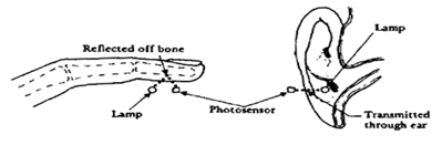
Heartbeat sensors use photoplethysmography (PPG). They measure the blood‑volume changes in a tissue, which alter the amount of light that is either transmitted or reflected. Because blood absorbs light, the variations in reflected or transmitted light directly correspond to the heart’s pulsations.
PPG is performed in two main ways:
Transmission: Light passes through a vascular region (e.g., earlobe) and is received on the opposite side.
Reflection: Light is reflected from the surface of the tissue (e.g., finger).
 How a Heartbeat Sensor Works
A typical sensor consists of an LED and a photodetector—either a photodiode or a light‑dependent resistor. When the LED illuminates tissue, part of the light is absorbed by the blood, and the remainder is reflected or transmitted to the detector. The detector’s electrical output contains a DC component (tissue absorption) and an AC component that syncs with each pulse.
To isolate the AC component, the detector output is filtered through a two‑stage high‑pass/low‑pass circuit, then converted to a digital pulse train using a comparator or an ADC. The pulse frequency (f) is fed to a microcontroller, which calculates BPM using the formula:
BPM = 60 × f
Practical Heartbeat Sensors
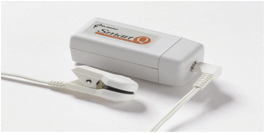
Common modules include the Heart Rate Sensor (Product No PC‑3147), which uses an infrared LED and an LDR on a clip that sits on the earlobe or finger.
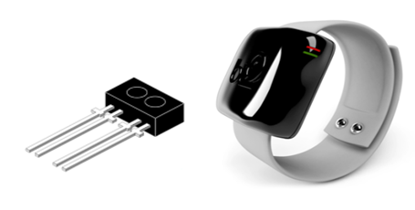
 Another popular choice is the TCRT1000, a 4‑pin optical sensor. Pin 1 supplies the LED, Pins 2 and 3 are ground, and Pin 4 delivers the output. When enabled, the sensor can be mounted on a wrist‑wearable and transmit data via Bluetooth for remote monitoring.
 Building a Simple Heartbeat Sensor System
A basic system can be assembled with an LDR, a comparator IC (LM358), and a microcontroller. The diagram below illustrates the typical circuit.
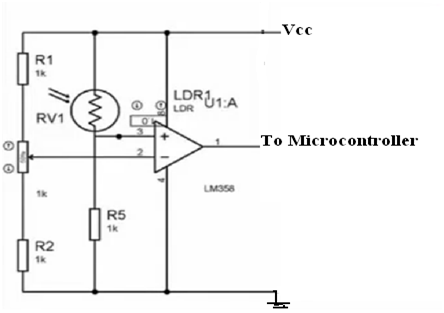
The LDR acts as the light detector: as light intensity rises, its resistance falls; as intensity drops, resistance rises. The LM358 compares the LDR’s voltage to a fixed threshold set by a voltage divider. When the tissue pulse reduces the light on the LDR, its resistance increases, raising the voltage above the threshold and producing a logic high. The resulting pulse train is fed to the microcontroller, which calculates the heart rate and displays it on an attached screen.
Video Explanation on Heartbeat Sensor Circuit Diagram
Sensor
- Blood Pressure Sensor: How It Works & Key Applications
- Voltage Sensors: How They Work & Key Applications in Modern Power Systems
- RVG Sensor: How It Works and Why It’s Transforming Dental Imaging
- Color Sensors: How They Work & Key Applications
- Fingerprint Sensor Technology: Working Principles, Applications, and Arduino Integration
- Ambient Light Sensors: Functionality, Design, and Key Applications
- Vibration Sensors: Principles, Types, and Industrial Applications
- How Oxygen Sensors Work and Their Key Applications in Automotive and Industrial Systems
- Sensor Telemetry 2.0.1 – Advanced Temperature Monitoring with Azure IoT Hub
- Light Sensors Unveiled: How They Work, Types, and Practical Uses