


Optimizing Seam Lines in FDM 3D Printing with Insight Seam Control
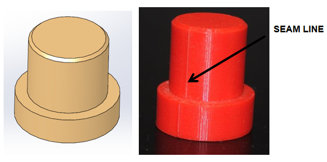
Building 3D parts with FDM technology presents unique challenges, one of the most noticeable being start/stop lines—commonly referred to as seam lines. On Fortus 250 mc and larger units, Insight, the bundled STL setup software, lets designers edit and reposition these seams through a feature called Seam Control. Note that Catalyst, used on desktop FDM units, does not support seam line editing.
Below is a simple boss extrusion example. The seam line runs down the boss and the base of the part. In a typical production run, manually filing or sanding thousands of parts would be impractical. In a recent project, a seam line interfered with a mating component, causing binding during assembly.
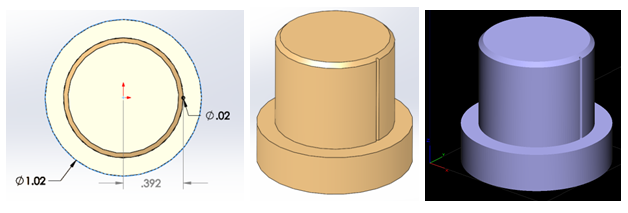
The solution was to modify the CAD model so the seam line would be tucked inside the geometry, eliminating interference. Using SOLIDWORKS, I sketched a circle on the boss’s top face. The circle’s center sat on the boss edge, and an extruded cut extended to the base’s top surface. I set the circle’s diameter to twice the layer height—for example, a 0.010″ layer height required a 0.020″ cut diameter. After these adjustments, I exported a new STL file for Insight.
In Insight, navigate to Toolpaths > Seam Control. With the feature enabled, the software shows the projected seam path. The default placement method is Automatic, but for precise control I switched to Align.
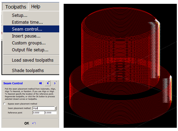
Select the boss’s edges to define the reference points. The dialog displays X and Y coordinates. To calculate X, use the formula: Center major OD edge to center of key + ½ major OD – Layer Height. For a major OD of 1.020″ and a 0.010″ layer height: 1.020/2 + 0.392 – 0.010 = 0.892″. For Y, simply divide the major OD by two: 1.020/2 = 0.510″. Enter these values and confirm.
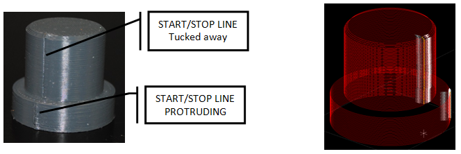
After exiting Seam Control, the print will automatically place the seam line within the modified geometry. The result is a clean part that functions immediately, with the seam hidden and no binding with mating components. If the base lacks a key cut, the seam will still protrude as before.
Holes and other features are handled the same way—repeat the steps to tuck seams into the model. This approach eliminates the need to file or sand thousands of parts, streamlining production while maintaining part quality. I will continue refining this process to achieve fully concealed seams.
Tags: FDM, Insight, Seam Control, seam lines, solid works, start stop lines
3D printing
- Control Circuits: Fundamentals, Applications, and Best Practices
- Birth Control Pills: History, Benefits, Risks, and Production
- Our Feature on CTV News London’s ‘London & Area Works’ – Highlighting Local Impact
- DIY Automatic Train Control with Arduino – Simple, Reliable, and Customizable
- Mastering Quality Control: Strategies for Consistent Excellence
- Varia Quick‑Change System – Rapid Tool Switching for EWS & Static Toolholders
- Hurco’s WinMax Integrated Control Empowers 11 Advanced Machine Tools
- Mastering Cast Film Line Control for Superior Packaging Results
- Mastering Cast Film Extrusion Lines: Achieve Precise Control & Superior Quality
- Haas RSJC: Efficient Stop, Jog, and Resume for CNC Milling and Lathes