


How Control Valves Operate: A Technical Overview
Control Valve Explained
Control valves automatically regulate pressure and flow in industrial processes. In facilities that run at elevated pressures or temperatures, Class 300 valves are mandated; using Class 300 valves throughout a plant guarantees interchangeability and consistent performance.
Globe valves are the most common type used for power control. Their flanged ends simplify maintenance, and the valve seat is moved by a disk that can be driven by hydraulic, pneumatic, electrical, or mechanical actuators. By moving the disk relative to the valve body, the valve modulates the cross‑sectional area available to the fluid, thereby controlling flow. The disk is attached to a stem that links directly to the actuator, enabling precise positioning.
These valves are engineered to withstand the dynamic forces of pressure, velocity, temperature, and inertia that characterize process streams. They absorb disturbances that could otherwise compromise product quality or upset network loops, maintaining critical variables within their operating envelopes.
To counteract load distortions, sensors and transmitters gather real‑time data on the process variable and compare it to a setpoint. A controller processes this information, determines the necessary corrective action, and sends a signal to the actuator. Once the control strategy is executed, the valve returns the process to its desired condition, closing the loop.
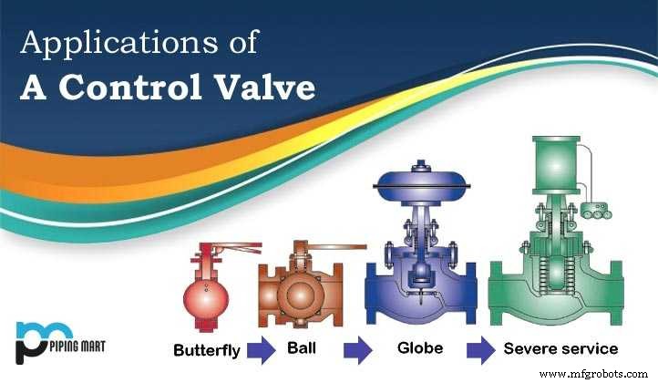
Applications of the Control Valves
Control valves serve as the final control element in most process loops, converting transmitter signals into mechanical motion that regulates the flow of air, steam, water, or chemicals. They account for roughly 15 % of total capital and maintenance spend in refining and chemical manufacturing sectors.
Despite their importance, control valves are often overlooked by instrument engineers because of unfamiliarity with the underlying disciplines—fluid dynamics, metallurgy, noise control, and piping design. Each loop typically consists of a sensor, a transmitter, a controller that compares the sensor’s output to the setpoint, and the control valve that enacts the correction.
In this way, the sensor provides the process state, the controller acts as the brain, and the valve functions as the muscle—together forming the most critical yet frequently misunderstood component of automated control systems.
Metal
- Understanding Full Mortise Hinges: Function, Installation, and Benefits
- Electrical Grounding Explained: Safeguarding Systems from Arcing and Fires
- How Casters Work: From Early Designs to Omni‑Directional Innovation
- Inside NASCAR Engines: Design, Power, and Training
- Understanding Pneumatic Valve Operation: A Practical Guide
- How SCADA Systems Operate: Monitoring and Controlling Industrial Processes
- How Air Dryers Work: Keeping Compressed Air Clean & Efficient
- Understanding Electric Brakes: How They Operate and Why They Matter
- How a 3D Pen Works: From Filament to Finished Model
- Understanding Hydraulic Flow-Control Valves: Function, Types, and Applications