


Simplifying Gate Circuits: Step‑by‑Step Boolean Algebra Techniques
Master the art of circuit simplification with a clear, systematic approach that reduces complexity, cuts power consumption, and boosts reliability.
We start with a semiconductor gate network that needs pruning. The signals A, B, and C are supplied by switches, sensors, or other gates—where they originate is irrelevant to the reduction process.
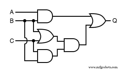
How to Write a Boolean Expression for Circuit Simplification
The first step is to express the circuit in Boolean terms. Label each gate output with a sub‑expression that reflects its inputs. Remember: OR gates map to addition (+), and AND gates map to multiplication (·).
For the initial three gates we obtain:
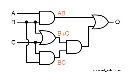
Proceeding to the next gate gives:
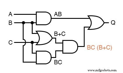
The final output, Q, is expressed as:
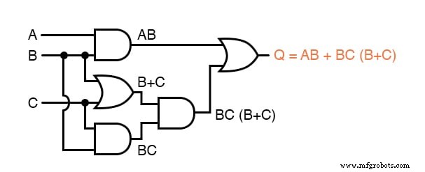
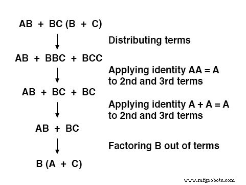
With a Boolean expression in hand, apply Boolean algebra to reduce it to its simplest form—defined as the fewest required gates. The reduction yields:
Verify the simplification by comparing truth tables for the original and reduced expressions; they will match across all eight input combinations.
Generating Schematic Diagrams from Boolean Expressions
Translate the simplified expression back into a schematic. Evaluate the expression using standard mathematical precedence—multiplication before addition, and operations within parentheses first—and instantiate the corresponding gates.
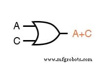
First, build the OR gate for the sub‑expression A + C:
Next, connect B to the OR output with an AND gate:

The resulting design uses only two gates instead of five, delivering faster response, lower power draw, reduced cost, and improved reliability.
Applying Boolean Simplification to Electromechanical Relay Circuits
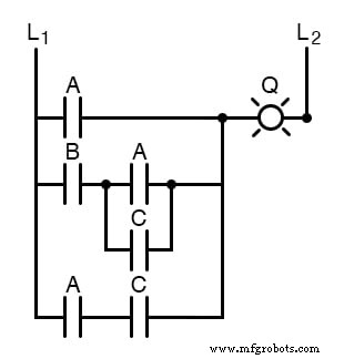
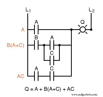
Relay circuits, while slower and more power‑hungry than semiconductor gates, also benefit from Boolean reduction. Consider this example:
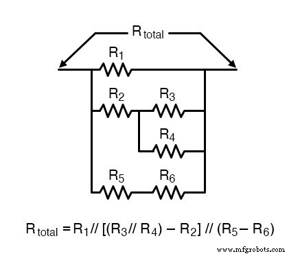
Start by converting the relay schematic into a Boolean expression. A useful analogy is reducing a series‑parallel resistor network: series contacts behave like multiplication, parallel contacts like addition.
For illustration, a comparable resistor network and its total resistance formula are shown:
When writing the Boolean expression, label each rung with a sub‑expression to keep the logic organized:
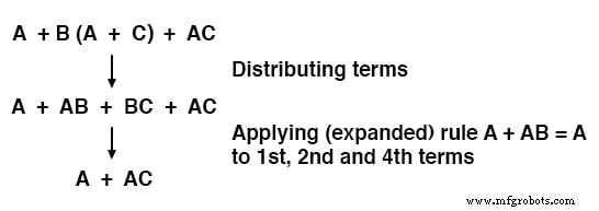
Apply Boolean algebra to collapse the expression to its simplest form. For instance:
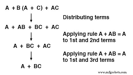
Mathematically, the rule A + AB = A can be extended to A + AB + AC + AD + … = A, allowing a single reduction step.
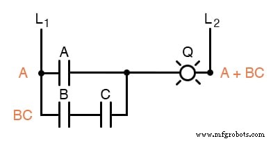
The simplified relay circuit maintains identical functionality while using fewer contacts:
Key Takeaways
- To convert a gate circuit into a Boolean expression, label each gate output with a sub‑expression and work up to the final output.
- To translate a Boolean expression back into a gate schematic, evaluate it following the order: multiplication first, then addition, respecting parentheses.
- For ladder logic, treat contacts like resistors: series contacts = multiplication, parallel contacts = addition. Collapse them step‑by‑step to a single expression.
- The reverse—building ladder logic from a Boolean expression—follows the same evaluation rules.
Related Worksheets
- Sum‑of‑Products and Product‑of‑Sums Expressions Worksheet
- Boolean Algebra Worksheet
Industrial Technology
- Circuit With a Switch: A Practical Guide to Basic Electrical Circuits
- Voltage Follower Amplifier: Design, Build, and Measurement Guide
- Mastering AC Circuit Equations: Impedance, Reactance & Resonance
- Getting Started with SPICE: A Text‑Based Circuit Simulation Tool
- Mastering SPICE Netlist Syntax: Component Naming, Passive & Active Elements, and Source Definitions
- Boolean Arithmetic: Adding, Multiplying, and Complementing in Digital Logic
- Essential Boolean Simplification Rules for Logic Circuit Design
- Demultiplexers Explained: How They Route Signals in Digital Circuits
- C# Expressions, Statements & Blocks: A Comprehensive Guide with Practical Examples
- Calculate the Correct Circuit Breaker Size: A Practical Guide & Online Calculator