


Key Performance Parameters of Electron Tubes
Electron tubes—those classic vacuum devices that once powered radios, televisions, and early computers—are still prized in high‑end audio, RF, and specialty amplifiers. Understanding their intrinsic parameters is essential for designing reliable, high‑performance circuits.
For bipolar junction transistors the most widely cited figure of merit is the current gain, or β, defined as the ratio of collector current to base current (– IC/IB). Electron tubes have comparable, well‑documented characteristics that have been quantified by electrical engineers for decades.
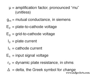
Before delving into those characteristics, we need to define the key variables that describe voltage, current, and resistance in a tube amplifier. The following diagram lists the most common terms used in analysis:
The two fundamental measures of an amplifying tube’s performance are its amplification factor, μ, and its mutual conductance, gm (also called transconductance). Transconductance is defined in the same way for voltage‑controlled devices such as field‑effect transistors. The equations are shown below:
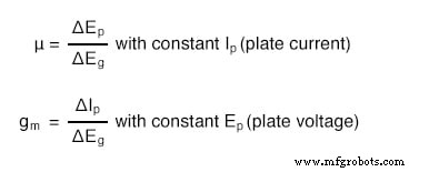
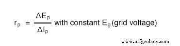
Another important, yet more abstract, metric is the plate resistance, rp. It represents the change in plate voltage per change in plate current while keeping the grid voltage fixed. In other words, it tells us how the tube behaves like a resistor for a given grid bias, analogous to a JFET operating in its ohmic region:
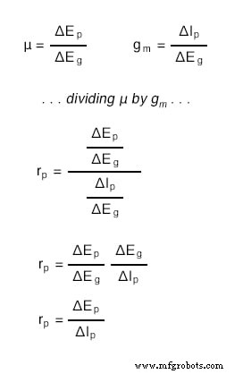
Notice that plate resistance can be derived by dividing the amplification factor by the transconductance:
These three parameters vary from tube to tube—just as β ratios differ between nominally identical bipolar transistors—and they shift with operating point. The variability stems from the inherent nonlinearity of electron flow and from the definitions of the figures of merit themselves. Even an ideal, perfectly linear tube cannot maintain constant μ, μ, and rp across all permissible operating ranges. For instance, a tube that regulates current perfectly for a given grid voltage (like a transistor with constant β) must still exhibit a plate resistance that changes with plate voltage, because the plate current remains unchanged while the plate voltage varies.
Despite this inherent variability, manufacturers provide standardized ratings for μ, gm, and rp at specified operating conditions, and many tubes publish detailed characteristic curves similar to those available for transistors. These data empower designers to model and predict tube behavior accurately in complex analog and RF systems.
Industrial Technology
- Variable Inductor Lab: Exploring Magnetic Permeability and Inductive Reactance
- The Triode: A Cornerstone of Vacuum Tube Technology
- The Tetrode Tube: Design, Function, and Impact on Amplifier Performance
- Pentodes: The Fifth Element for Enhanced Tube Performance
- Combination Tubes: Merging Multiple Functions into a Single Glass Envelope
- Display Tubes: From CRTs to Cat‑Eye Indicators
- Microwave Tube Technology: From Klystrons to Magnetrons
- Alloy 31 Stainless Steel Plate – Superior Strength & Ductility for Extreme Environments
- High-Performance Aluminium Alloy Plate – Sidesupport, Header, Tube Plate (O) MG36
- Alloy 52 Plate – High-Performance Nickel-Iron Composite for Industrial Applications