


Mixed‑Frequency AC Signals: Coupling, Harmonics, and Practical Insights
In our study of AC circuits, we have examined circuits powered by a single‑frequency sine voltage waveform. In many real‑world applications, however, single‑frequency signals are the exception rather than the rule.
Often, circuits contain multiple frequency components simultaneously, and waveforms may deviate from a pure sine shape—what we call non‑sinusoidal waveforms. In addition, DC may be superimposed on AC, producing signals that vary in magnitude but not polarity, or that spend unequal time in positive versus negative halves.
Since DC does not alternate, its frequency is considered zero. Any signal that contains both DC and AC components is therefore a mixed‑frequency signal, and such signals are common in practice.
When multiple frequencies coexist in the same circuit, analysis becomes more complex than the simple single‑frequency case.
Coupling
Mixed‑frequency voltage and current can arise accidentally through unintended electrical coupling—typically caused by stray capacitance or inductance between conductors. A frequent industrial example occurs when DC signal wiring runs close to AC power cables. The high AC voltage and current can induce “foreign” voltages or currents on the signal conductors.
Stray capacitance, formed by the insulation separating power and signal conductors, can transfer voltage relative to earth ground. Stray inductance, created by parallel runs of wire, can induce voltage along the signal conductors through electromagnetic coupling.
The result is a blend of DC and AC at the signal load, as illustrated by the schematic below:
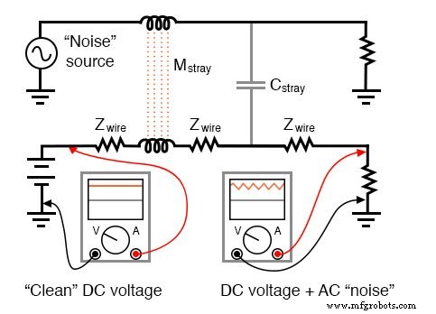
Stray inductance and capacitance couple stray AC into desired DC signal.
When stray AC voltages from a noise source mix with DC signals, the outcome is typically undesirable. To avoid this, power wiring and low‑level signal wiring should be routed through separate, dedicated metal conduits, and signals should travel via shielded twisted‑pair cable rather than a single wire with a ground reference:
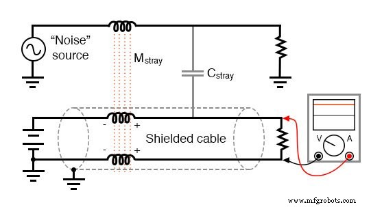
Shielded twisted pair minimizes noise.
The shield—either a braid or foil wrapped around the two insulated conductors—blocks external electric fields, preventing capacitive coupling. The close proximity of the two conductors cancels inductive coupling: any induced noise voltage is nearly equal in magnitude and opposite in phase on both conductors, resulting in a differential noise voltage that is almost zero.
Polarity markers near inductive segments illustrate how the induced voltages phase‑shift to cancel each other.
Coupling can also occur between two sets of AC conductors, leading to mutual mixing of their signals:
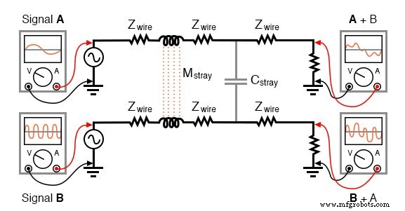
Coupling of AC signals between parallel conductors.
In most cases, such coupling is accidental and unwanted. Nonetheless, mixed‑frequency signals are intentionally generated in many applications, and they are also inherent to certain signal sources.
One simple way to create a mixed‑frequency source is to connect voltage sources in series, as shown below:
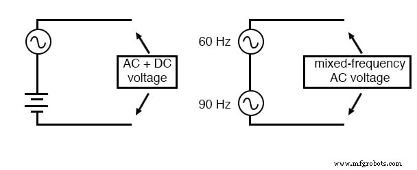
Series connection of voltage sources mixes signals.
Computer‑networking systems sometimes superimpose high‑frequency data onto 60 Hz power‑line conductors to transmit information over existing cabling. Power‑distribution networks have employed this technique for decades to convey load data along high‑voltage lines.
Single‑source devices can also produce mixed frequencies. For example, microphones convert audio‑frequency air‑pressure waves into voltage waveforms. A pure tone yields a single sine wave, while complex sounds generate a rich mixture of frequencies that reflects the underlying acoustic content.
Fundamental and Harmonic Frequencies
Musical chords arise from blending a fundamental frequency with harmonics that are integer multiples of that fundamental. Even a single piano note contains a dominant fundamental tone plus a series of higher‑frequency harmonics.
Below is a table illustrating these terms with a hypothetical fundamental of 1000 Hz:
| Frequency | Term |
|---|---|
| 1000 | 1st harmonic (fundamental) |
| 2000 | 2nd harmonic |
| 3000 | 3rd harmonic |
| 4000 | 4th harmonic |
| 5000 | 5th harmonic |
| 6000 | 6th harmonic |
| 7000 | 7th harmonic |
Overtone
The term overtone refers to a harmonic frequency produced by a particular instrument. The first overtone is the first harmonic above the fundamental; for a full harmonic series the second overtone is the third harmonic, and so forth. However, not all instruments generate every harmonic. For instance, a tube that is open at one end and closed at the other—such as a bottle—cannot produce even‑numbered harmonics. A 1000‑Hz fundamental from such an instrument would yield 3000, 5000, 7000 Hz, but no 2000, 4000, or 6000 Hz components.
A pure sine wave lacks harmonics and therefore sounds flat and featureless. The distinctive timbre, or color, of a musical instrument comes from the unique blend of its fundamental and harmonic amplitudes. Brass, woodwind, and stringed instruments each have characteristic harmonic signatures that define their tone.
Instruments that vibrate two‑dimensional surfaces, such as steel drums or certain bells, generate a broader spectrum of frequencies that are not limited to whole‑number multiples of the fundamental, producing tones that some listeners find acoustically rich or even dissonant.
Music offers a fertile ground for studying mixed frequencies and their perceptual effects. Subsequent sections of this chapter will delve deeper into the use of musical instruments as waveform sources for analysis.
Review
- A sinusoidal waveform has the exact shape of a sine wave.
- A non‑sinusoidal waveform can be a distorted sine or any other shape, such as a square wave.
- Mixed‑frequency waveforms may arise accidentally, intentionally, or as a natural consequence. Most musical tones are rich blends of multiple frequencies.
- When multiple sine waves mix, the lowest frequency is the fundamental, and its integer‑multiple counterparts are the harmonics.
- An overtone is a harmonic produced by a specific instrument; the first overtone is the first frequency above the fundamental, but the sequence depends on which harmonics the instrument can generate.
Related Worksheets
- Mixed‑Frequency Signals Worksheet
- Mutual Inductance Worksheet
Industrial Technology
- Verilog Basics: Designing Your First AND Gate
- Foundations of DC Circuits: Understanding Direct Current and Core Electrical Concepts
- Understanding AC Circuits: A Beginner's Guide
- Getting Started with SPICE: A Text‑Based Circuit Simulation Tool
- Analog and Digital Signals: Foundations of Industrial Instrumentation
- Current Signal Systems: The 4‑20 mA Loop Explained
- Understanding Square Wave Signals: Fundamentals and Applications
- Foundations and Advancements of AC Motor Technology
- Understanding Electrical Harmonics: Part 1 – Fundamentals & Impact
- Ensuring Signal Integrity in High-Speed PCB Design